Raspberry Pi Compute Dev Kit - BCM2835 32Bits ARM
Contents
Introduction
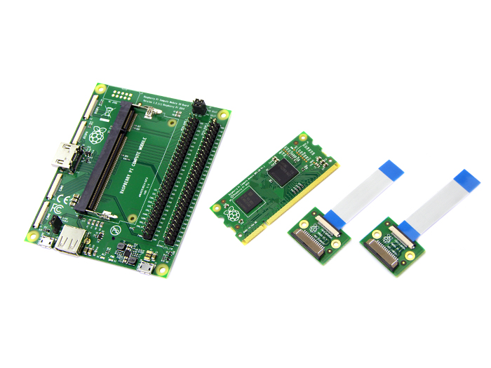
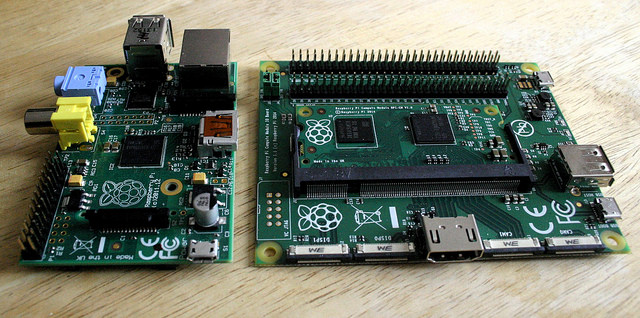
Sometimes the Raspberry Pi seems too big for us if we don’t have much room for it. At this time, we may desire for a smaller Pi. The Raspberry Pi compute module is a small compact module which has the same key ingredients and performance as a regular Pi. It’s so slim that can fit into a DDR2 memory slot. The compute module contains the BCM2835 processor and 512Mbyte of RAM as well as a 4Gbyte eMMC Flash device. This module is designed for people who want to create their own PCB. The compute module IO board is a board produced for the compute module. The board provides the power to the module, the HDMI and USB connectors to make up an entire system. You can program the module’s Flash memory; access the interfaces via the board. So if you are going to create your own PCB, this kit must be your best choice.
Features
- Full flexibility of the BCM2835 SoC
- many more GPIOs and interfaces are available as compared to the Raspberry Pi
- 32 bits
- Flexible & Rapid Prototype Development
- Aimed at business and industrial users
- Large Range of GPIOs & Interfaces
- On board 4GB eMMC Flash memory
Specifications
- BCM2835 processor and 512Mbyte of RAM
- 67.6x30mm board
- 4GB of eMMC Flash
- micro USB connector type B
- 2 x CSI ports for camera boards
- 2 x DSI ports for display boards
- standard DDR2 SODIMM connector
- Full size HDMI port
- Micro USB power connector
Hardware resources
Power Supply
The Compute Module has six separate supplies that must be present and powered at all times; you cannot leave any of them unpowered, even if a specific interface or GPIO bank is unused. The six supplies are as follows:
- VBAT powers the BCM2835 processor core. It feeds the SMPS that generates the chip core voltage.
- 3V3 powers various BCM2835 PHYs, IO and the eMMC Flash memory.
- 1V8 powers various BCM2835 PHYs, IO and SDRAM.
- VDAC powers the composite (TV-out) DAC.
- GPIO0-27_VREF powers the GPIO 0-27 IO bank.
- GPIO28-45_VREF powers the GPIO 28-45 IO bank.
Note that the voltage range for best SMPS efficiency is ~3.3 - 4.3V.
Run the kits
- Setting up
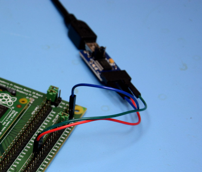
The IO board provides HDMI and USB host ports for hooking up a display and input devices. However, my preferred hardware console is a trusty serial connection, and so with the Compute Module inserted into the SO-DIMM socket on the IO board, I connected up a USB UART.
Power was then supplied via the Micro USB connector labelled Power In.
- Resources
The Compute Module boots in just the same way as the Raspberry Pi Model A or B, with the difference being that the boot device is on-board flash storage rather than an SD card.
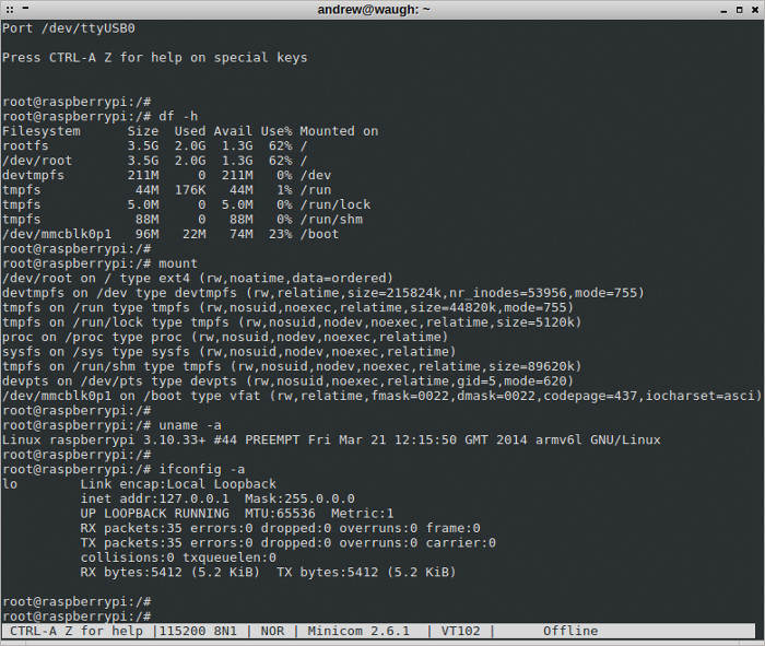
Logging in and executing a few familiar commands we see that we have a root filesystem of 3.5GB and that the only network interface is loopback.
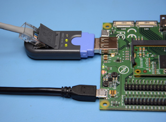
I decided to connect a USB Ethernet adapter to see if this would provide a new network interface.
However, while the Ethernet adapter powered up and was detected by Linux, it wasn't supported by the kernel or a loadable module. So it looks as though adding support for peripherals will require copying a new kernel or modules onto the on-board flash — which should be simple enough to do.
- Hello World
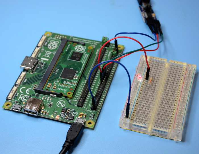
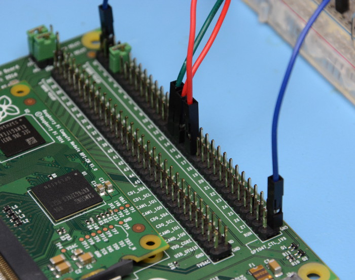
As mentioned previously the IO board provides plenty of 0.1” breakout, and just to confirm that the GPIO pins functioned as expected I hooked up an LED and attempted to toggle the pin from the bash prompt. Sure enough, upon exporting the pin, setting its direction to output and value to 1, the LED illuminated. No surprises here!
- Bountiful prototyping
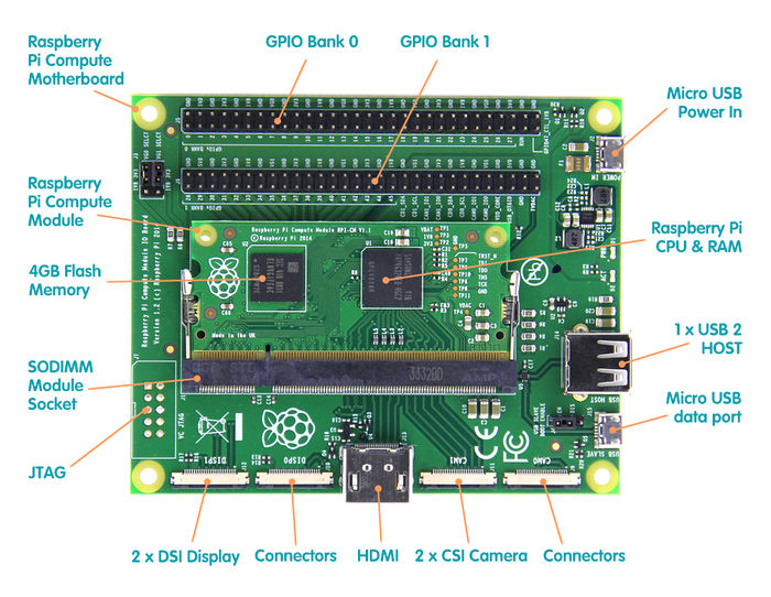
The IO board provides access to 46 pins of GPIO, which is a good deal more than you get with a Raspberry Pi Model A or B. In addition to which the 0.1” pitch headers also provide plenty of GND, 1v8, 3v3 and 5v power pins. And just above the two long rows of headers are jumpers which allow you to set the logic levels for pins 0-27 and 28-45 respectively, to either 1v8 or 3v3.
Interestingly, the J15 Micro USB connector is labelled “USB BOOT”. From notes in the schematic it appears that this is used to boot the module from a USB connected host, and once booted access is provided to the on-board flash. Presumably this is how you would load an O/S and applications.
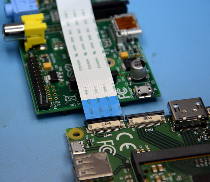
The board also provides CSI and DSI ports for serial cameras and displays — double the number in fact, with two of each.
Although the connectors used for these ports are higher density than those used with a Model A or B, and so at the very least new flex cables will be required. My guess is that the current Raspberry Pi cameras will be supported via a new cable — but that remains to be seen.
Install an OS on to the compute
Typically a Raspberry Pi requires an SD card to store the operating system, mostly Raspbian. But as the Compute has an on-board 4GB of eMMC this is no longer required, but the trick is how do we get our OS on to it? Well with the Compute Module firmly inside the CMIO we need to download a copy of Raspbian (dated 20/6/2014 or greater) and then extract the image to our computer. At the time of writing only a Linux host system can be used to flash the eMMC of the Compute, you can of course use your spare Raspberry Pi.
On the CMIO you will see a jumper marked “J4” USB SLAVE BOOT ENABLE, make sure that this is set to “EN”.
On your Linux computer ensure that the date and time is correct. If necessary use the following command in a terminal.
sudo date MMDDhhmm
Where MM = Month DD = Day, hh = hours and mm = minutes.
Once that date has been checked complete the following lines, remembering to press enter at the end of each line.
sudo git clone --depth=1 cd tools/usbboot sudo apt-get install libusb-1.0-0-dev
This will clone a github repo that contains all of the files necessary to interact with the Compute.
Navigate to the directory where the git files were downloaded. We now need to make a tool which will enable our host machine to talk to the Compute module.
sudo make
With the tool built, now is the time to start the connection process. In the terminal issue the following command.
sudo ./rpiboot
Following the last command, your host computer will now wait for the CMIO to be attached, and to do that you will need to insert a micro USB to USB connection between the two. The micro USB connection will attach to the CMIO USB slave port and the standard USB connection will attach to your host computer.
Your host computer should now register that the CMIO has been successfully attached. We will now need to identify where the device has been mounted using the following command.
mount
Typically the device will be mounted as “/dev/sdX” where X is the letter associated with your Compute, but please ensure that you correctly identify the drive BEFORE running the next command.
With the drive associated to our Computer correctly identified we now need to copy the Raspbian image that we downloaded earlier to the eMMC of the Compute. To do this we will use a command called “dd”. This command will copy the image, piece by piece to the eMMC and will take around 10 minutes to complete. You will need to navigate to the location of the extracted image file that we downloaded earlier.
sudo dd if=raw_os_image_that_you_downloaded.img of=/dev/sdX bs=4MiB
Remember to change "raw_os_image_that_you_downloaded.img" to the name of your Raspbian image, and to change “X” to match the location of your Compute module.
Always double check BEFORE running this command as dd is fairly unforgiving if you choose the wrong drive.
Now that the operating system as been copied to the Compute we are free to unplug the USB from our host computer, but before we test our Compute, lets put the USB back in to the host computer to check that the process was successful.
The easiest way to check is via your file manager, two new drives should be made available, one of which will have a FAT file system, the other a Linux file system. If this is the case, congratulations your Compute is ready for action. If not, repeat the above steps to find any issues.
Now that they Compute is ready, remove the micro USB connection to your host computer, and return J4 to it's original position. Connect up your HDMI, USB hub with peripherals attached, and finally power up the CMIO board.
Your Compute should now boot as per a typical Raspberry Pi sequence.
Resource
Instruction Media:Rpi compute modules instruction.pdf
Schematic Media:Rpi compute modules schematic.pdf
How to buy
Click here to buy: http://www.geeetech.com/raspberry-pi-compute-dev-kit-bcm2835-32bits-arm-p-866.html
