Geeetech Mizar S 3D Printer
Introduction
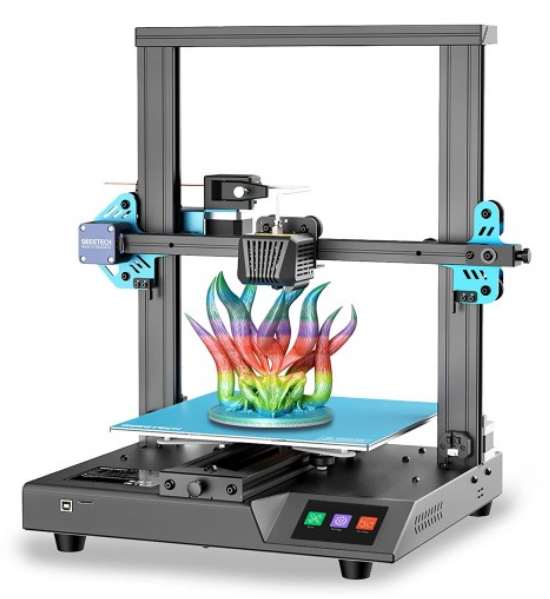
Geeetech Mizar S is a very good 3D printer with a medium print volume on the market. It has many premium features such as the automatic print bed leveling and the flexible print bed, it is also very well suited for beginners.
Mizar S uses a dual gear Bowden extruder, that is lightweight and compact in design, allowing higher speeds and generating less vibration. The extruder of the Mizar S has two drive gears. This gives greater extrusion force and control over the filament than standard Bowden extruders with only one active drive gear.
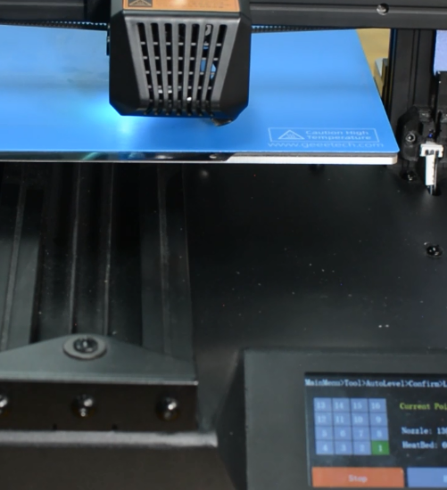
The print bed of the Geeetech Mizar S doesn’t have any screws with which you can manually change the tilt. Instead, the print bed is mounted stationary and the print head has a built-in sensor that allows it to measure the distance to the print bed.
A dual Z-axis in a 3D printer increases accuracy because there is a stepper motor on each side of the Z-axis to move the X-axis in the Z-direction. This results in a more stable movement in the Z direction, which leads to higher accuracy when printing objects.
Main Specification
Printer Type FDM
Layer Thickness 0.1-0.3 mm
Printing Material PLA,ABS, PETG, Silk PLA, Wood Polymer
Building Platform Volume 255*255*260 mm
Auto-leveling Yes
Break Resuming Yes
Preheat time(110℃) 7 min
Nozzle Diameter 0.4 mm
Positioning Precision X axis: 0.011 mm;Y axis: 0.011 mm;Z axis: 0.0025 mm;
Printing Accuracy ±0.1 mm
Printing Speed 10~150 mm/S; recommend 60~80 mm/s
Display Screen 3.5” Colorful Touch Screen
Operating System Windows, Mac, Linux,
Slicing Software Repetier-Host, EasyPrint Lite, Cura
Supported File Format .gcode
Hotbed Max. Temperature 110 ℃
Extruder Max. Temperature 250 ℃
Environmental Temperature 10-40 ℃
Electrical Parameter
Power Input 115/230 V AC, 50/60 Hz
Power Output DC 24 V-15 A Max, 360 W
Connectivity Interface 1*TF Card, 1*USB cable
Power Supply Unit Certification CE, FCC,ROSH
Mechanical Parameter
Printing Size 255*255*260 mm
Net Weight(kg) 8.9 kg
Gross Weight(kg) 11.2 kg
Printer Whole Size 362(W)*377(L)*653(H)mm
Packing Dimension 522(L)*482(W)*310(H)mm
Watch the unboxing video and user manual before assembling the printer.
Printer maintenance
How to replace a hotend
Mizar S hotend kit is available in our website: Mizar S hotend kit
Watch video tutorial: How to replace the hotend of Mizar S
| Tools necessary for this guide |
|---|
| Wrench size 10 mm
Allen keys – 1.5/2/2.5/3 mm Flat screwdriver tip width 2.5 mm Diagonal pliers Electrical tape Zip ties Craft knife or equivalent |
Step 1 Preparing
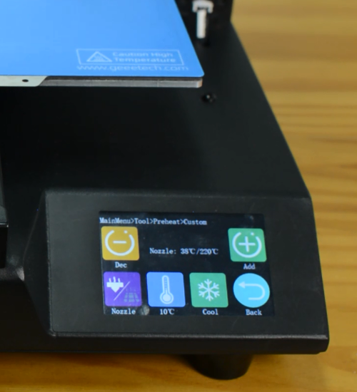
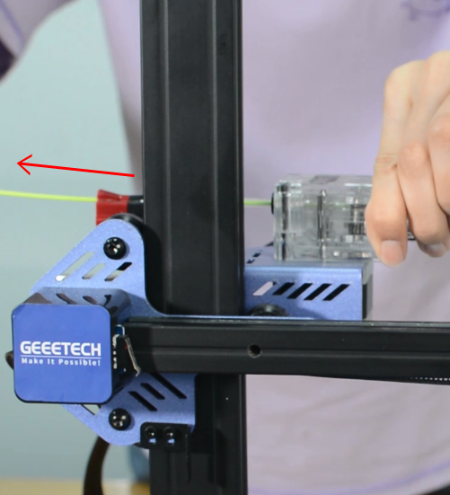
Preheat the nozzle to 220 Celsius from the LCD menu, then unload the filament from the hotend.
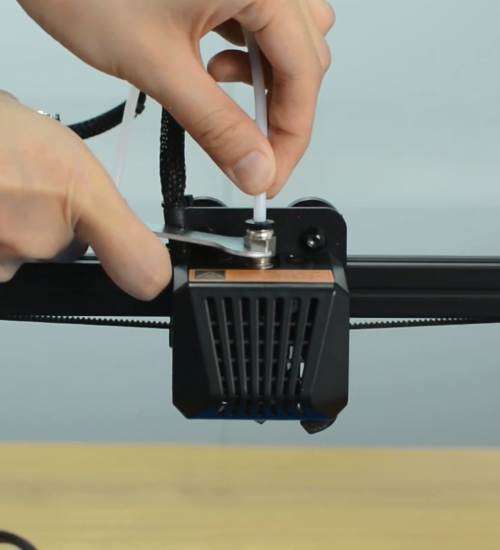
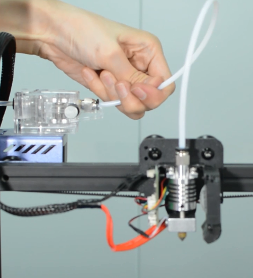
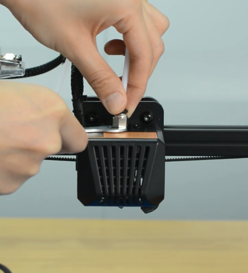
Remove the Teflon tube from the hotend.
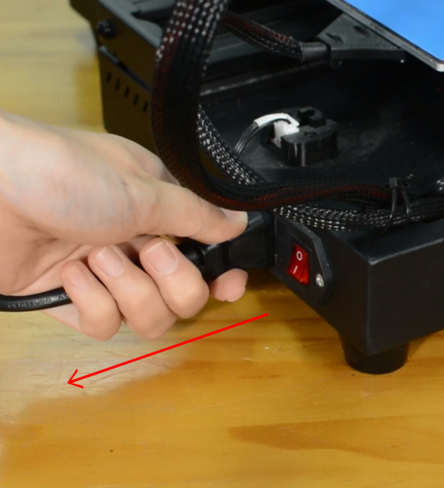
Before moving to step 2, remember to turn the printer off and unplug it from the socket!
Step 2 Disassembling the hotend
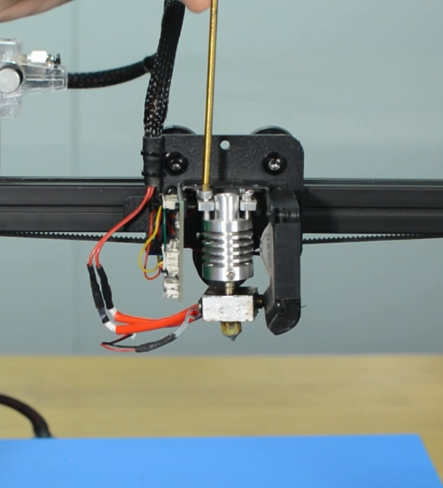
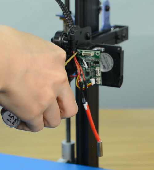
Remove the hotend housing and disconnect the hotend thermistor.
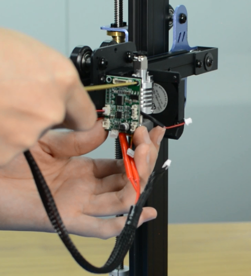
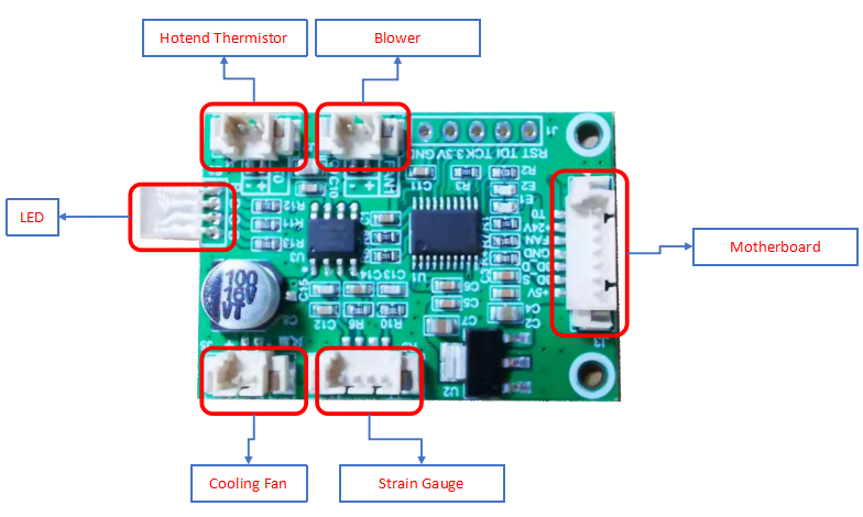
Release and remove the two screws that secure the hotend, then unplug all the cables on the extension board.
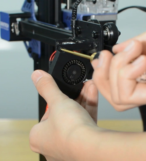
Remove the extension board and the part cooling fan.
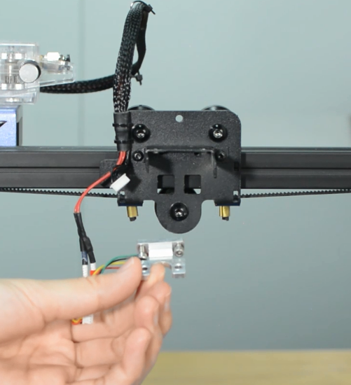
Remove the strain gauge.
Step 3 Disconnecting the hotend cables
Remove the bottom cover and disconnect the cooling fan.
Disconnect the heater cartridge.
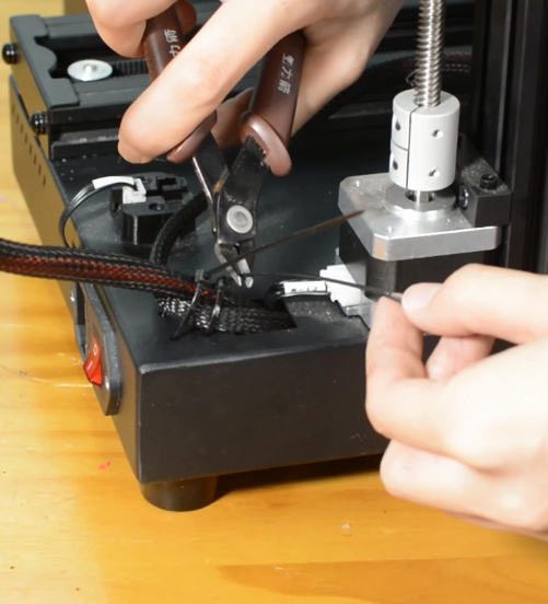
Cut off the heat-shrink tubing from the connection wire. Avoid cutting the cable.
Remove the old heater cartridge.
Step 4 Install the new hotend kit
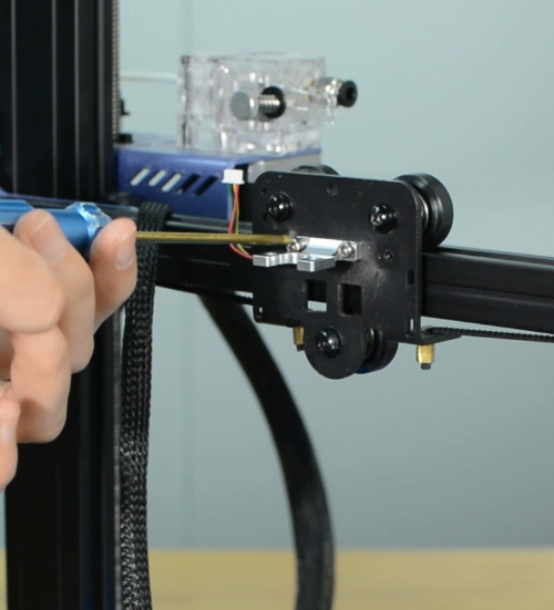
Fix the new strain gauge.
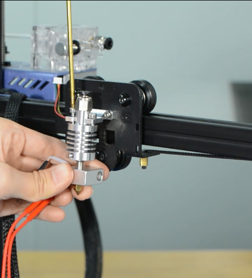
Install the new hotend.
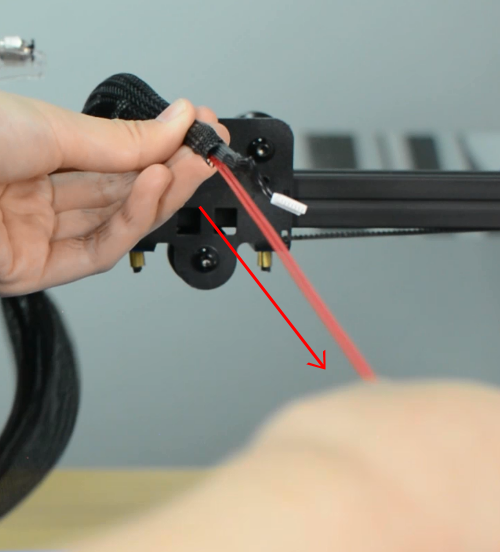
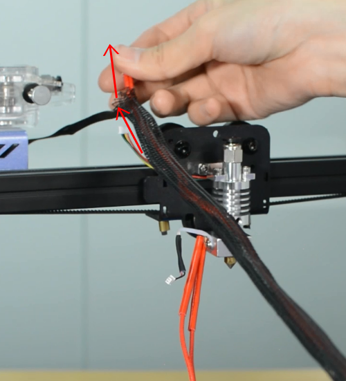
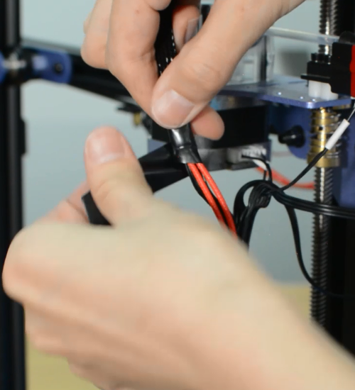
Run the cables of heater cartridge through the textile sleeve.
Insert the both heater cables into the connector.
Make sure the cables are fully inserted and tightened!
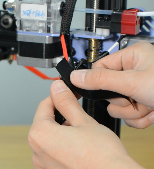
Tighten the textile sleeve with electrical tape.
Tighten the zip ties and cut the remaining parts.
Install the part cooling fan and extension board.
Connect all the hotend cables to the extension board.
Step 5 Install the PTFE tube
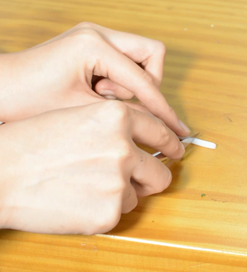
Take the razor or knife and carefully trim the tube. The Teflon ends should remain flat. Uneven ends may cause hotend to jam.
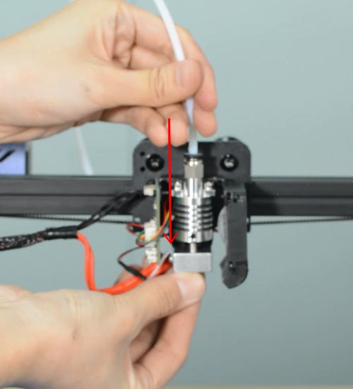
Insert and push the new PTFE tube into the heatbreak all the way down.
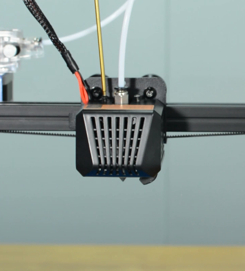
Install the print head housing.
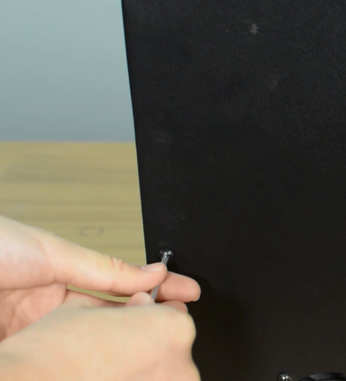
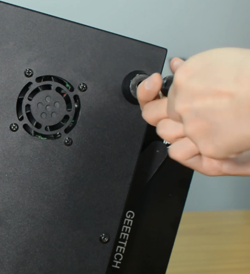
Plug the cooling fan back in and secure the base cover with screws.
It's done! Plug in the printer and turn it on to check whether the printer works properly.
How to clean the hotend and replace a nozzle
| Tools necessary for this guide |
|---|
| Tweezers for nozzle
Wrench size 6/10/20 mm Cleaner rod (1.5mm diameter, 100mm length) Needle for nozzle Allen key - 2 mm |
The nozzle for Mizar S is available in our website: 5pcs* Nozzle for Mizar S
Watch video tutorial: How to clean hotend and replace nozzle of Mizar S
Step 1 Clean the hotend
Preheat the nozzle to 220 Celsius from LCD menu.
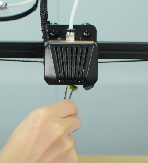
Clean the surface of the nozzle with tweezers.
Unload the filament from the hotend.
Remove the Teflon tube from the hotend.
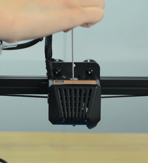
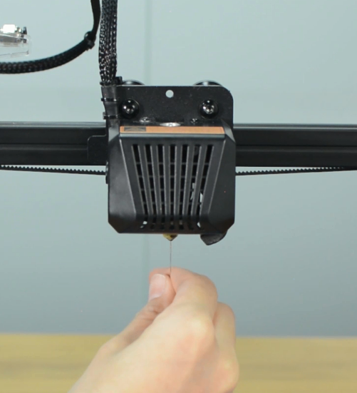
Use a cleaner rod (1.5 mm diameter, 100 mm length) to push it in and out several times, making the clog out. Do not use excessive force.
Use a needle to clean the nozzle.
Step 2 Replace a nozzle
Turn the printer off.
Remove the print head housing.
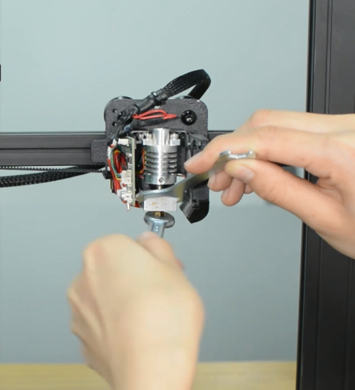
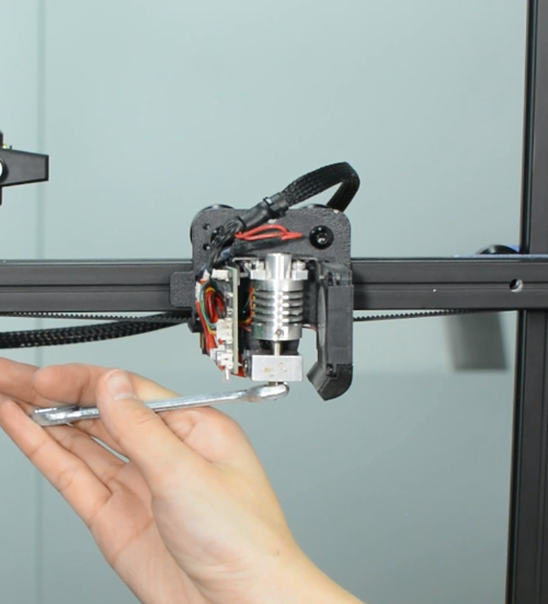
Release the old nozzle with a 6mm spanner while holding the heater block in place with a 20mm spanner.
Install the new nozzle and tighten it gently, but firmly. Do not use excessive force!
Place the silicone sock for heater block.
Install the print head housing.
Insert and push the new PTFE tube into the heatbreak all the way down.
How to replace a control board
| Tools necessary for this guide |
|---|
| Allen keys – 2.5/3 mm
Flat screwdriver tip width 2.5 mm |
The control board is available in our website: Mizar S control board
Watch video tutorial: How to replace the control board of Mizar S
Turn the printer off and unplug the power cable!
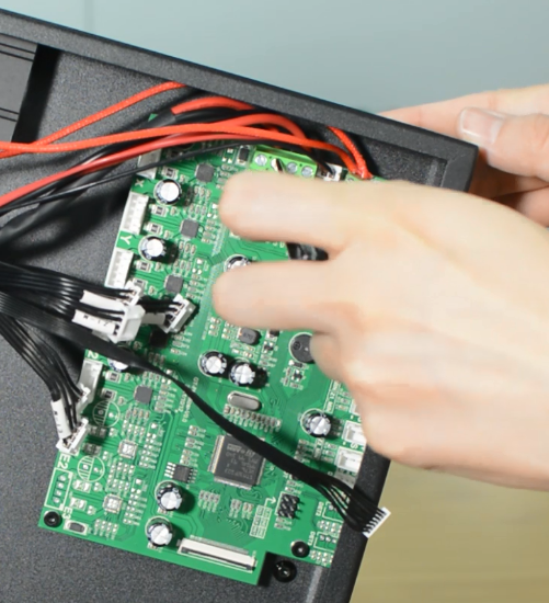
Remove the bottom cover, unplugging the cooling fan.
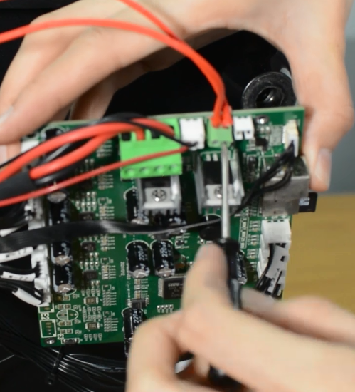
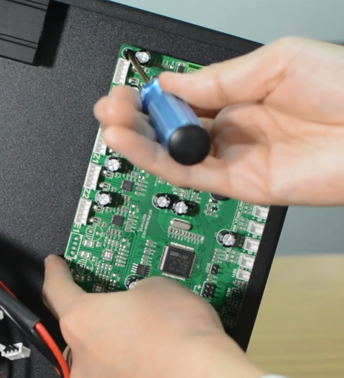
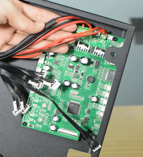
Disconnecting all the cables.
Replace with a new control board and tighten the screws securely.
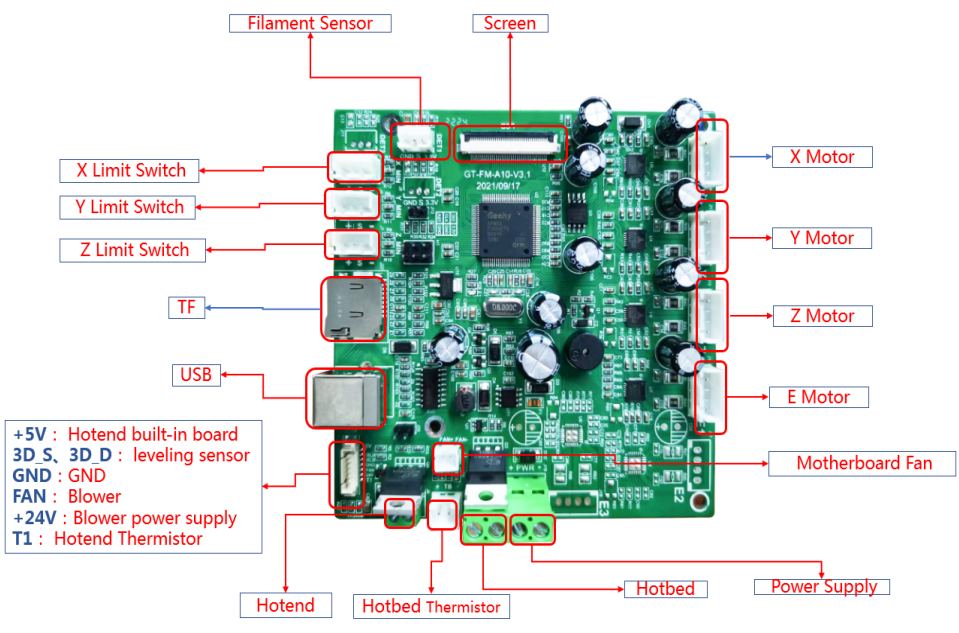
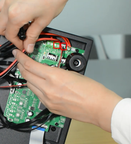
Plug in all the connections as the picture below.
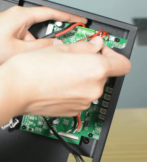
Insert the cables of power supply and hotbed. Red wire is positive and black wire is negative.
Make sure the cables are fully inserted and tightened!
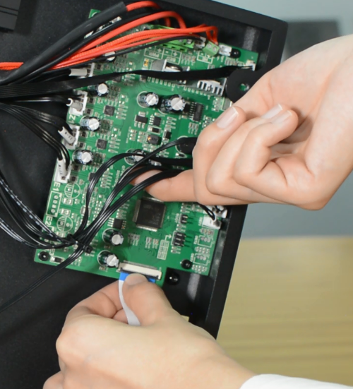
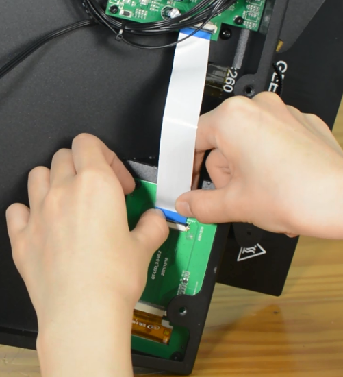
Connect the LCD cable.
Plug the cooling fan back in and secure the base cover with screws.
It's done! Plug in the printer and turn it on to check whether the printer works properly.
How to replace PSU
| Tools necessary for this guide |
|---|
| Allen keys - 2.5/3 mm
Philips screwdriver for PSU cables |
The power supply is available in our website: Mizar S power supply
Watch the video tutorial: How to replace the power supply of the Mizar S
Turn the printer off and unplug it from the socket.
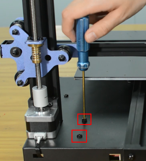
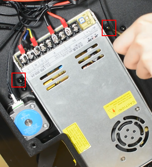
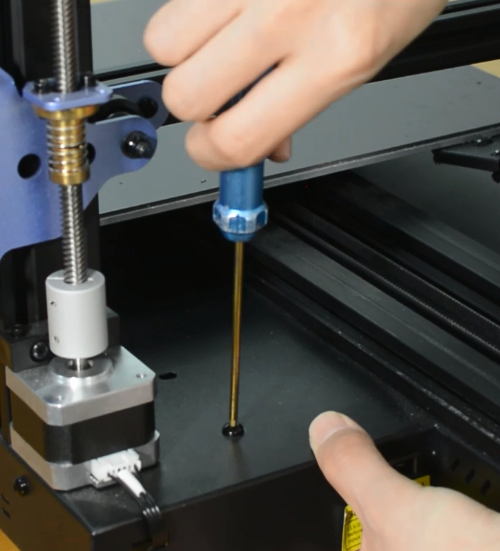
Release and remove the two screws that secure the PSU.
Remove the bottom cover, unplugging the cooling fan.
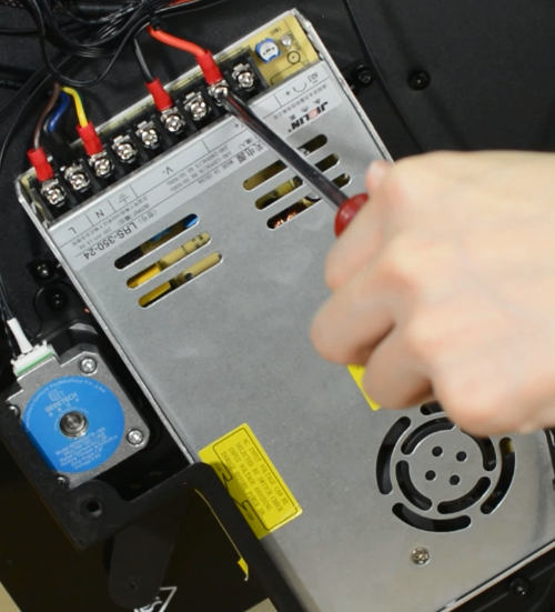
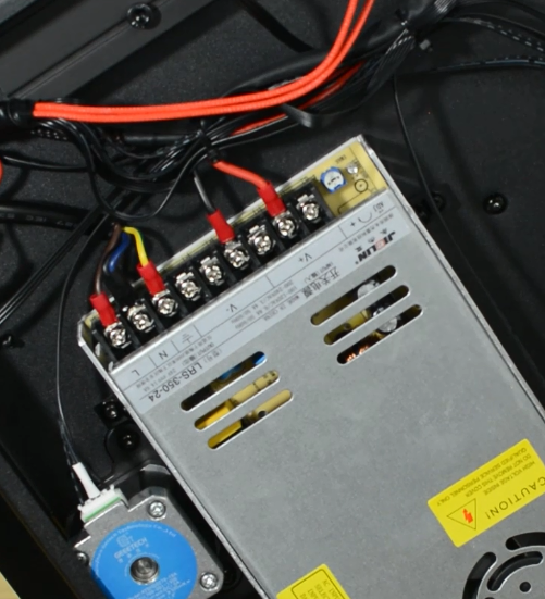
Using a Philips screwdriver release all five screws.
Release and remove the two screws that holding the PSU and make sure you hold it before releasing the last screw.
Assembling the new PSU.
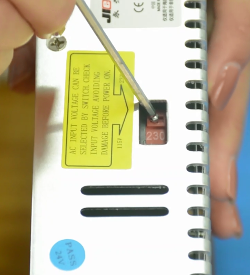
Ensure that the DIP switch of the power supply is adjusted to the right voltage!
Please triple-check you have connected the cables correctly!
There is a risk of damaging the PSU or the printer itself, if the cables are connected incorrectly or not tightened properly!
Tighten the two screws.
Plug the cooling fan back in and secure the base cover with screws.
How to replace a hotbed
| Tools necessary for this guide |
|---|
| Allen keys – 3 mm
Flat screwdriver tip width 2.5 mm Diagonal pilers Zip ties |
The hotbed is available in our website: Mizar S hotbed kit
Watch video tutorial: How to replace the hotbed of Mizar S
Turn the printer off and unplug it from the socket!
Remove the bottom cover, unplugging the cooling fan.
Disconnect the hotbed cable and hotbed thermistor.
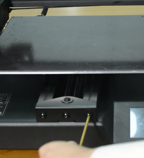
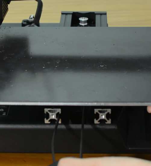
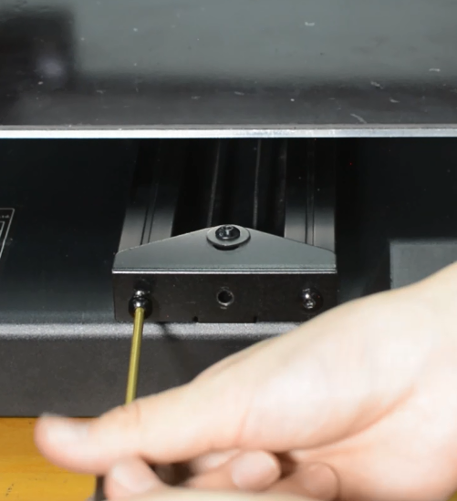
Release and remove the three screws of the Y-axis rail.
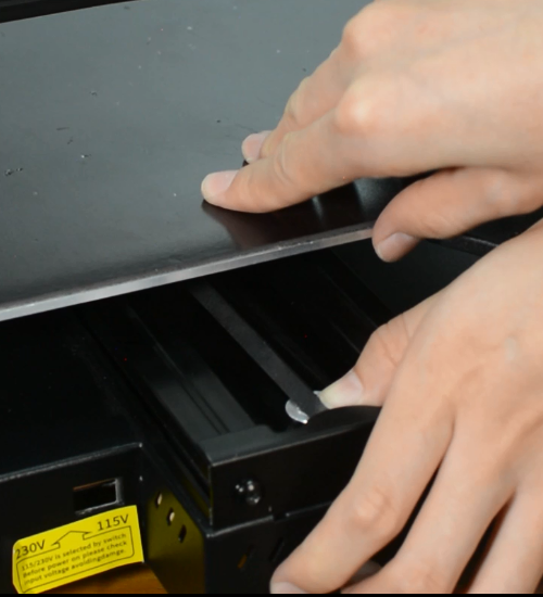
Remove the hotbed from the printer.
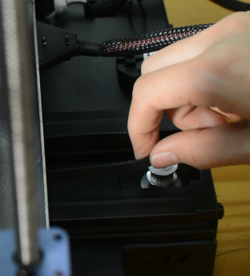
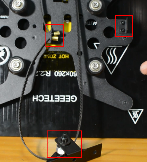
Install the new hotbed kit and pay attention to how the Y-axis belt is installed as the pictures below.
Tighten the three screws.
Connect the hotbed thermistor and hotbed cable.
Plug the cooling fan back in and secure the base cover with screws.
How to replace a screen
| Tools necessary for this guide |
|---|
| Allen keys - 2.5/3 mm |
The screen is available in our website: Mizar S touch screen
Watch video tutorial: How to replace the touch screen of Mizar S
Turn the printer off and unplug the power cable!
Remove the bottom cover, unplugging the cooling fan.
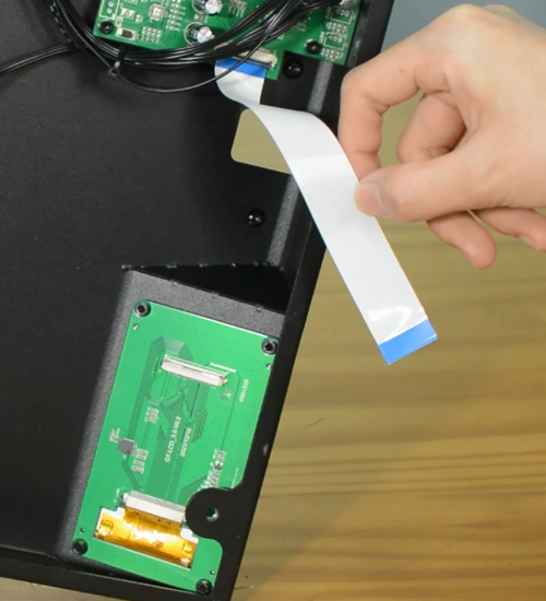
Unplug the screen connector and put it to the side.
Release and remove four screws on screen.
Set the screws in place, tighten the screws.
Connect the LCD cable.
Plug the cooling fan back in and secure the base cover with screws.
How to replace a filament sensor
The filament sensor will be worn out after long time use. We’ve uploaded a filament guide on our website to fix this.
And thanks to the 3D printer community, there’re lots of upgrade mods on the website for reference.
Geeetech Mizar S filament roller guide by by JTProuhet
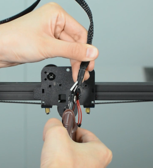
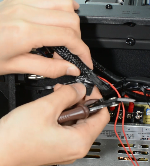
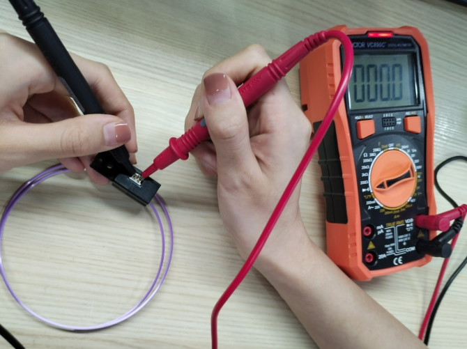
If there’s error on the screen prompts like “Change Filament” even filament has been uploaded, maybe the sensor is broken. You can test it by a multimeter.
Remember load a small piece of filament through the sensor before test. By touching each of the measurement leads of the multimeter to the two pins of the sensor, a signal (beep or 0 value on the multimeter screen) will indicate that the component is intact and therefore, should work.
Trouble shooting
Mintemp Error
The Mintemp error in 3D printers is a design feature within your firmware for safety in regard to temperature. When below a set temperature, the heater will be switched off due to possibly having a broken thermistor wire. It can be observed a negative the temperature on the LCD screen.
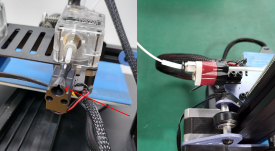
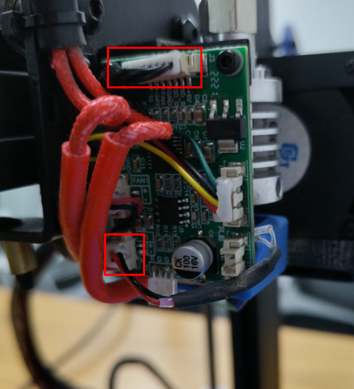
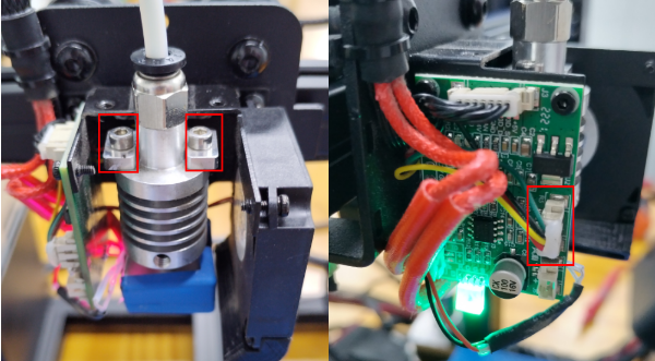
Check if the hot end connector and thermistor are connected properly as the pictures below. Check the hotend cables and thermistor, make sure they’re not broken or burn out.
You can test the thermistor by a multimeter. If it fails to read the resistance, then the wire is broken. At room temperature, it should be 80 kΩ - 125 kΩ. Or apply heat to the thermistor with a heater, blow-dryer or other heating device. The resistance should decline steadily in seconds if it works. If not, replace it.
Another common reason behind getting the MINTEMP error is from being in a cold environment, especially in winter months. Your 3D printer is designed to have a minimum temperature that it can operate in as a safety feature.
Update Firmware
Download the latest firmware in our website
How to update:
1.Put "bin” file and "assets” folder in TF card root directory, insert TF card into the printer.
2.Turn on the printer, the screen will display the firmware upgrade progress bar.
3.After the progress is complete, the printer starts to upgrade UI.
4.Update is complete.
Notice:
1.After the upgrade, delete the bin file and assets folder in the TF card to prevent repeated upgrades.
2.Level the hotbed after the upgrade is complete.
Consumables stick to the hot bed
The spring steel sheet is flexible and easy for part removal. But keep in mind that prints are easy to remove after the plate cools down. Don’t try to forcefully remove the object when the sheet is still hot. We do not suggest you use the adhesive on the sheet, because the adhesive is difficult to clean up and may have an opposite effect.
If there’re leftover residue on the sheet, preheat the hotbed to 80 degrees to make the plastic soft. Then use the wet cloth wiping the plate and gently scrap the residue off.
A dirty bed will cause poor first layer adhesion. You need to remove the dirt, leftover residue or oil from the bed surface. Isopropyl alcohol (IPA) 90%+ will help to degrease the platform.
Consumables don't stick to the hot bed
(a)Nozzle is too close to the hotbed Even though the extruder is working but no filament is depositing on the hotbed, Check if the nozzle is too close to the hotbed. Adjust the Z-offset value slightly will help.
(b)Print temperature is too low Some filament needs more higher temperature, manually feed the filament, if it can not be extruded, please try increase the print temperature.
(c)The extruder is not working Check if the grub screw on the extruder gear. If the grub screw is loose, the gear will fail to grab the filament when feeding into the hotend. Also check if the extruder motor is connected properly.
Automatic leveling failed
(a)Nozzle calibration failed
You should use a scraper against the nozzle and gently push up to make the nozzle “feel” the pressure. If this still fails, check if the strain gauge in the hotend is connected properly, and ensure the cables are not broken.
(b)Homing failed
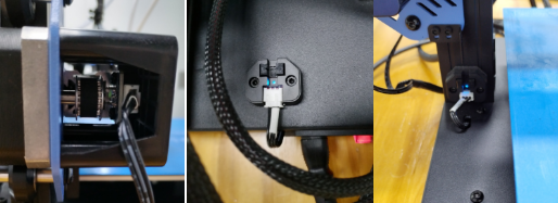
Check the X, Y and Z axes end stops, make sure they’re all connected properly. Note the photoelectric end stops on the Y and Z axes, which normally have a blue signal light. You can home the X, Y and Z axes one by one to check which axis is faulty.
(c)The first layer is messy
Please clean the hotbed before printing, this will help to get a good adhesion. We recommend a thicker first layer, 0.3 mm is good. If these’re not helpful, please try to adjust the Z-offset. What’s more, you can try adjust the hotbed temperature, for example, the Geeetech wood PLA needs a lower hotbed temperature but PETG needs higher. Consumables don't stick to the hot bed
Black screen
Warning: Never install or unplug anything on a printer while it’s being powered!
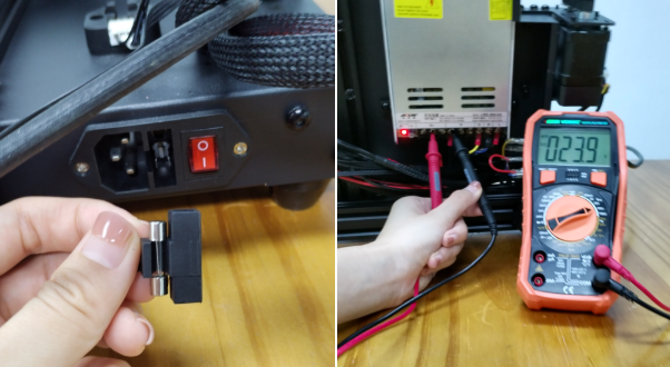
(a)Please check if the power supply is working normally. The red indicator on the switch should be light. And also check the fuse in the little black box, it should be complete without burns. Please measure the output voltage, which should be around 24 Volts.
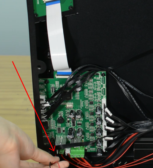
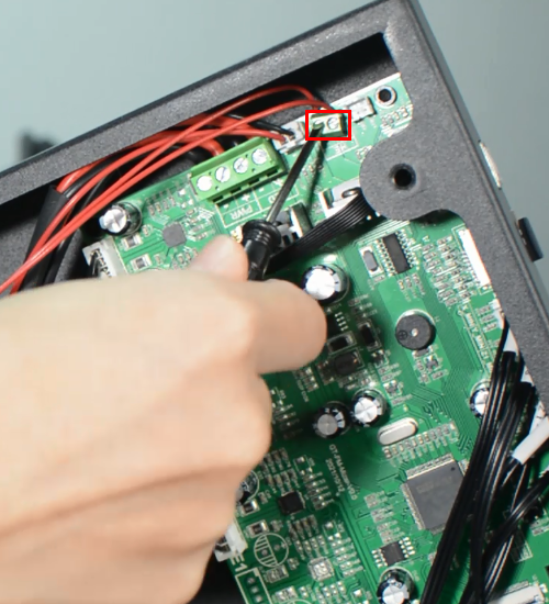
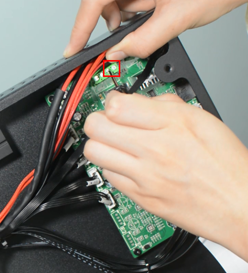
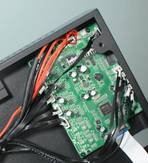
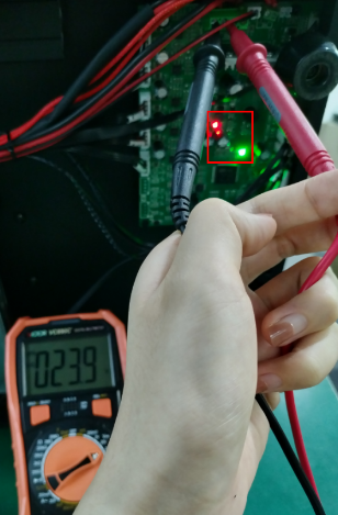
(b)Please check if the control board is working normally. There’re one green LED and one red LED working as the picture shown below. Measure the input voltage of the control board, it should be around 24 Volts.
(c)Make sure the screen is connected properly.
The extruder keeps making a click sound
(a)Decrease the print speed. If the print speed is too fast, the extruder will push the filament too quickly. Filament may not have enough time to melt and even clog in the nozzle. A clogged nozzle will then exert pressure back on the extruder, resulting in clicking. For PLA, our recommended print speed is 60mm/s.
(b)Increase the print temperature. If the temperature is too low, it will not melt the filament properly. This can also clog the nozzle. As the extruder is no longer able to push the filament ahead, it starts “slipping”.
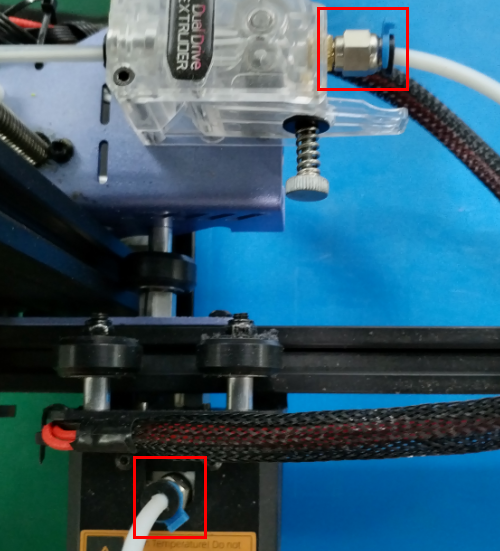
(c)Check the pneumatic fittings. A loose coupling could therefore allow molten filament to leak into a gap between the tube and the nozzle. This will restrict the flow of the filament, causing the extruder keep clicking.
(d)Change the extruder gear. After many hours of use, the teeth of the extruder may eventually wear out. Thus, it can no longer hold the filament, leading to filament slipping in the extruder.
(e)A low-tension extruder arm bar. If spring tension is too low, the extruder gear will not properly grip the filament. This leads to filament grinding.
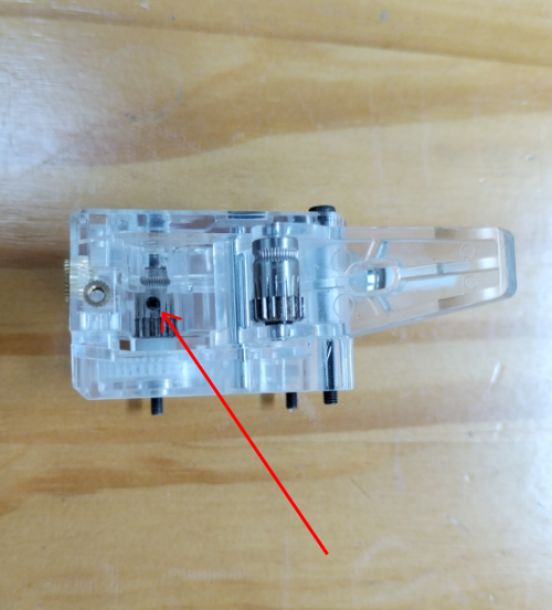
(f)Check if the grub screw on the extruder gear. If the grub screw is loose, the gears will fail to grab the filament when feeding into the hotend.
