Geeetech Mizar S 3D Printer
Contents
Introduction
Product details
Unpacking and proper handling
Slicing
Printer maintenance
How to replace a hotend
Mizar S hotend kit is available in our website: Mizar S hotend kit
Watch video tutorial: How to replace the hotend of Mizar S
| Tools necessary for this guide |
|---|
| Wrench size 10 mm
Allen keys – 1.5/2/2.5/3 mm Flat screwdriver tip width 2.5 mm Diagonal pliers Electrical tape Zip ties Craft knife or equivalent |
Step 1 Preparing
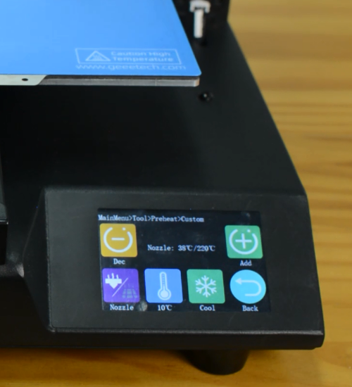
Preheat the nozzle to 220 Celsius from the LCD menu, then unload the filament from the hotend.
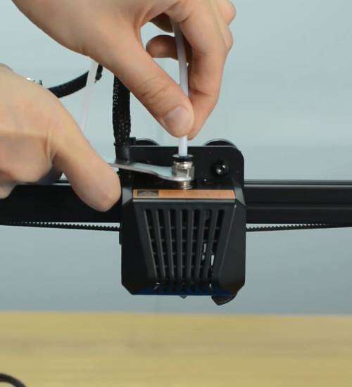
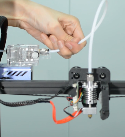
Remove the Teflon tube from the hotend.
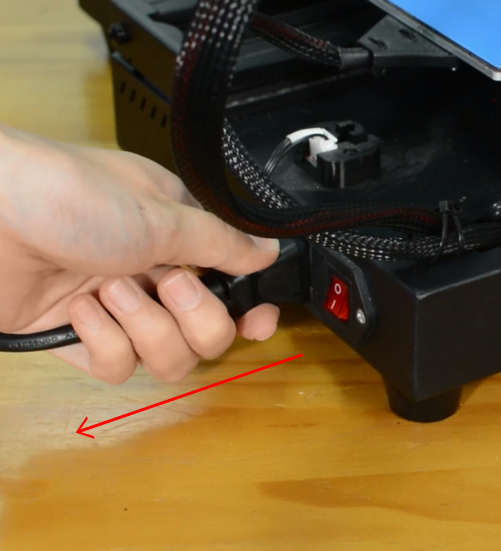
Before moving to step 2, remember to turn the printer off and unplug it from the socket!
Step 2 Disassembling the hotend
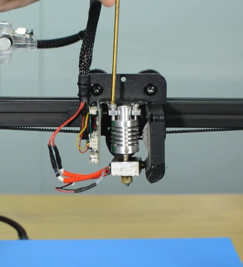
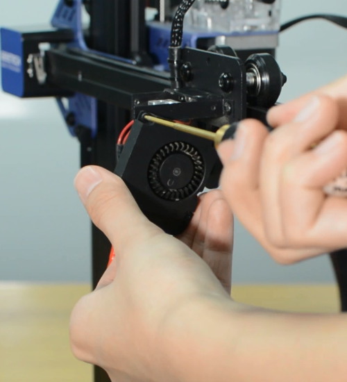
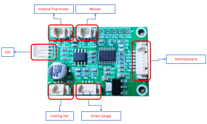
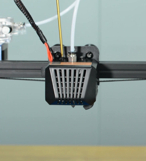
Remove the hotend housing and disconnect the hotend thermistor.
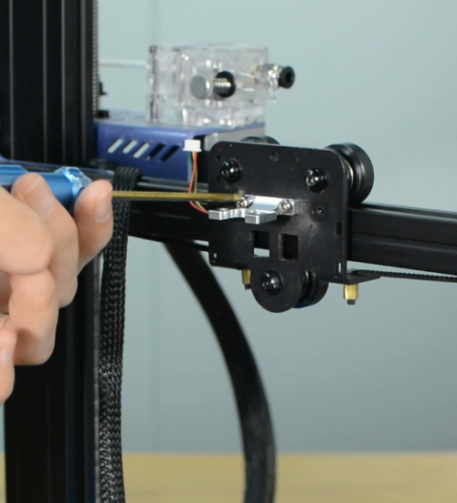
Release and remove the two screws that secure the hotend, then unplug all the cables on the extension board.
Remove the extension board and the part cooling fan.
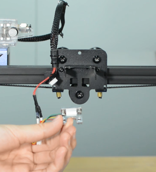
Remove the strain gauge.
Step 3 Disconnecting the hotend cables
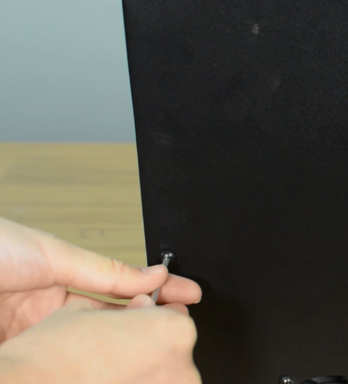
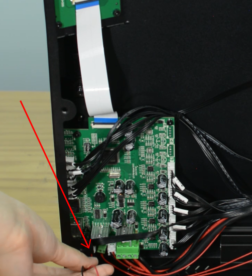
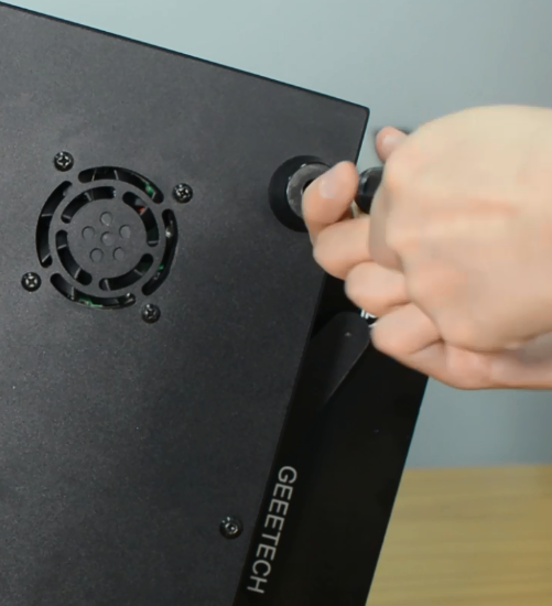
Remove the bottom cover and disconnect the cooling fan.
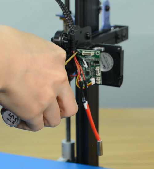
Disconnect the heater cartridge.
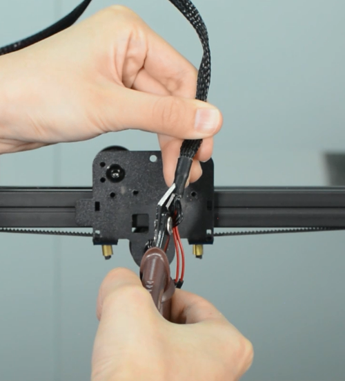
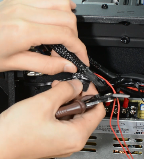
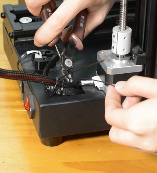
Cut off the heat-shrink tubing from the connection wire. Avoid cutting the cable.
Remove the old heater cartridge.
Step 4 Install the new hotend kit
Fix the new strain gauge.
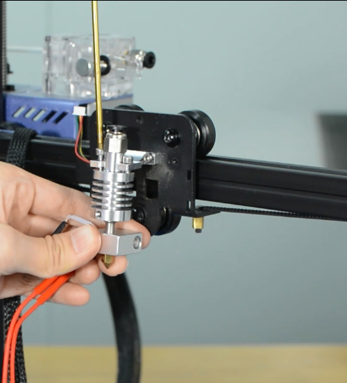
Install the new hotend.
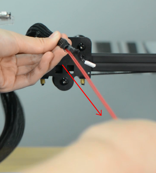
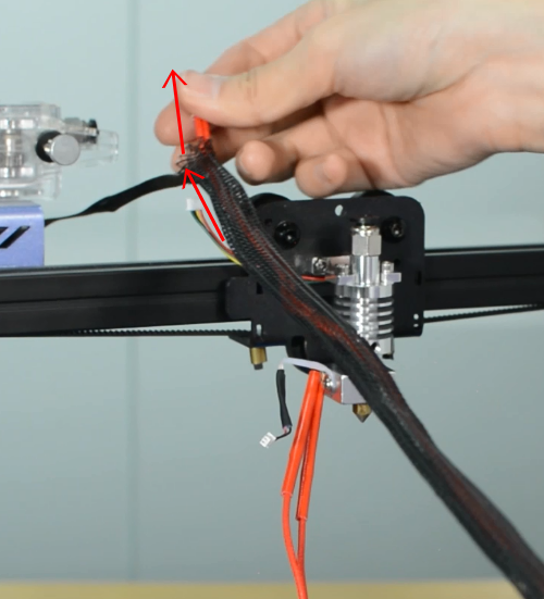
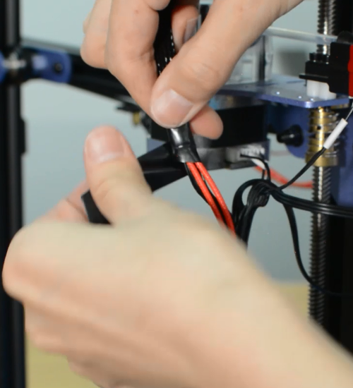
Run the cables of heater cartridge through the textile sleeve.
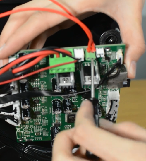
Insert the both heater cables into the connector.
Make sure the cables are fully inserted and tightened!
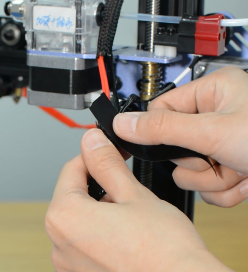
Tighten the textile sleeve with electrical tape.
Tighten the zip ties and cut the remaining parts.
Install the part cooling fan and extension board.
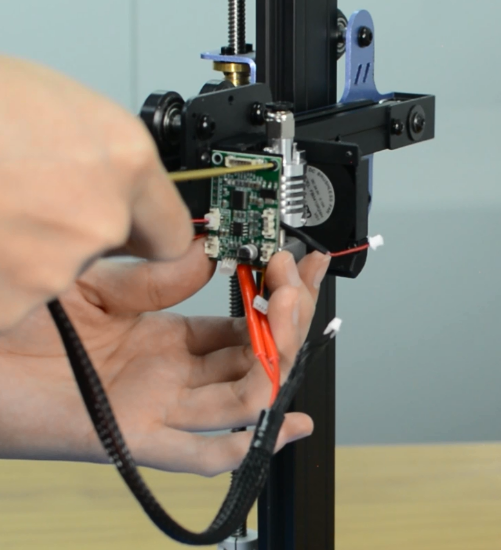
Connect all the hotend cables to the extension board.
Step 5 Install the PTFE tube
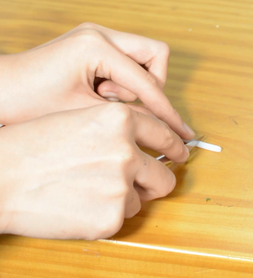
Take the razor or knife and carefully trim the tube. The Teflon ends should remain flat. Uneven ends may cause hotend to jam.
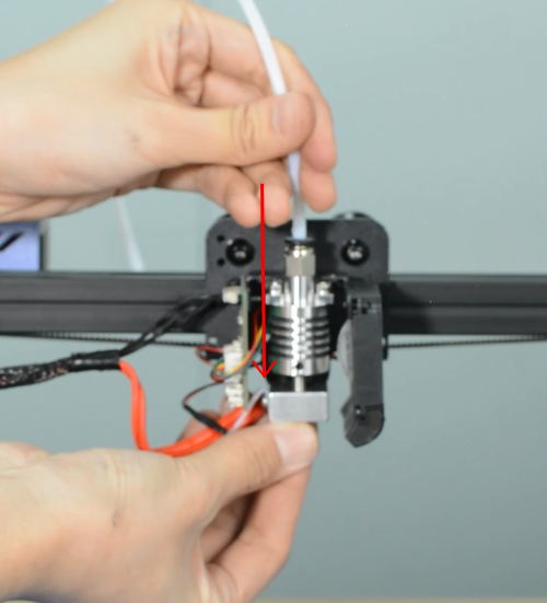
Insert and push the new PTFE tube into the heatbreak all the way down.
Install the print head housing.
Plug the cooling fan back in and secure the base cover with screws.
It's done! Plug in the printer and turn it on to check whether the printer works properly.
How to clean the hotend and replace a nozzle
| Tools necessary for this guide |
|---|
| Tweezers for nozzle
Wrench size 6/10/20 mm Cleaner rod (1.5mm diameter, 100mm length) Needle for nozzle Allen key - 2 mm |
The nozzle for Mizar S is available in our website: 5pcs* Nozzle for Mizar S
Watch video tutorial: How to clean hotend and replace nozzle of Mizar S
Step 1 Clean the hotend
Preheat the nozzle to 220 Celsius from LCD menu.
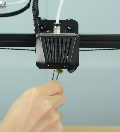
Clean the surface of the nozzle with tweezers.
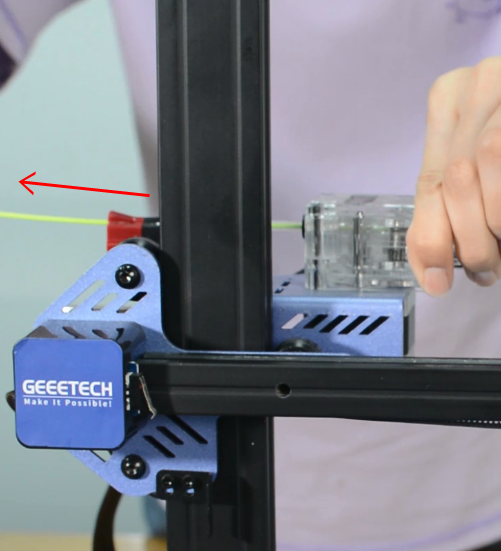
Unload the filament from the hotend.
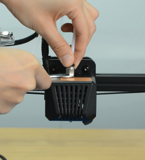
Remove the Teflon tube from the hotend.
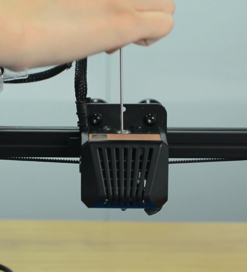
Use a cleaner rod (1.5 mm diameter, 100 mm length) to push it in and out several times, making the clog out. Do not use excessive force.
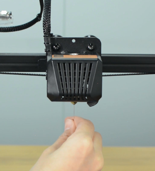
Use a needle to clean the nozzle.
Step 2 Replace a nozzle
Turn the printer off.
Remove the print head housing.
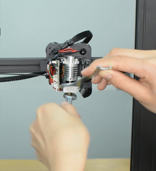
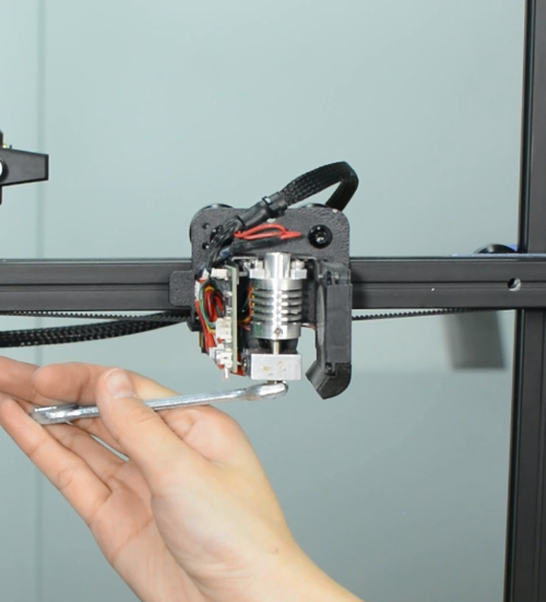
Release the old nozzle with a 6mm spanner while holding the heater block in place with a 20mm spanner.
Install the new nozzle and tighten it gently, but firmly. Do not use excessive force!
Place the silicone sock for heater block.
Install the print head housing.
Insert and push the new PTFE tube into the heatbreak all the way down.
How to replace a control board
| Tools necessary for this guide |
|---|
| Allen keys – 2.5/3 mm
Flat screwdriver tip width 2.5 mm |
The control board is available in our website: Mizar S control board
Watch video tutorial: How to replace the control board of Mizar S
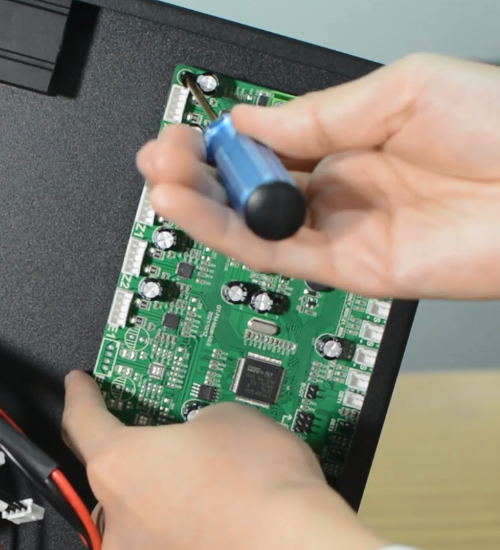
Turn the printer off and unplug the power cable!
Remove the bottom cover, unplugging the cooling fan.
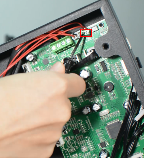
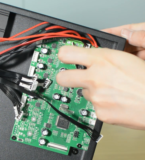
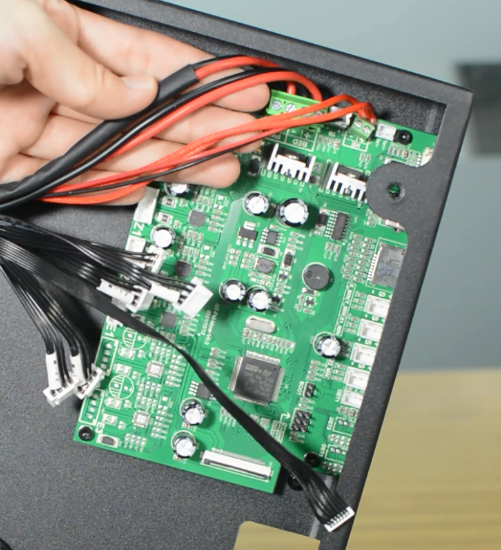
Disconnecting all the cables.
Replace with a new control board and tighten the screws securely.
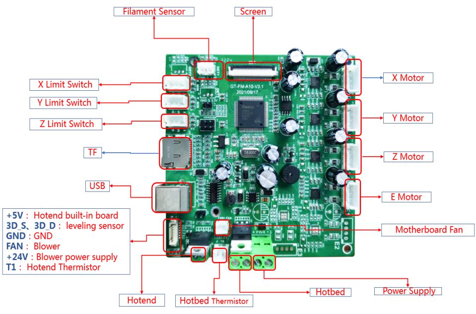
Plug in all the connections as the picture below.
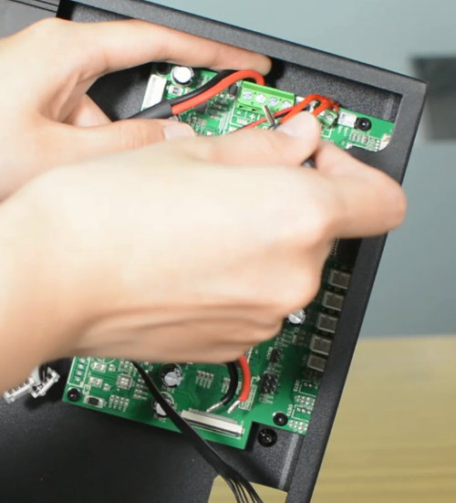
Insert the cables of power supply and hotbed. Red wire is positive and black wire is negative.
Make sure the cables are fully inserted and tightened!
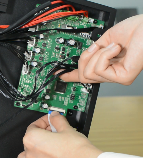
Connect the LCD cable.
Plug the cooling fan back in and secure the base cover with screws.
It's done! Plug in the printer and turn it on to check whether the printer works properly.
How to replace PSU
| Tools necessary for this guide |
|---|
| Allen keys - 2.5/3 mm
Philips screwdriver for PSU cables |
The power supply is available in our website: Mizar S power supply
Watch the video tutorial: How to replace the power supply of the Mizar S
Turn the printer off and unplug it from the socket.
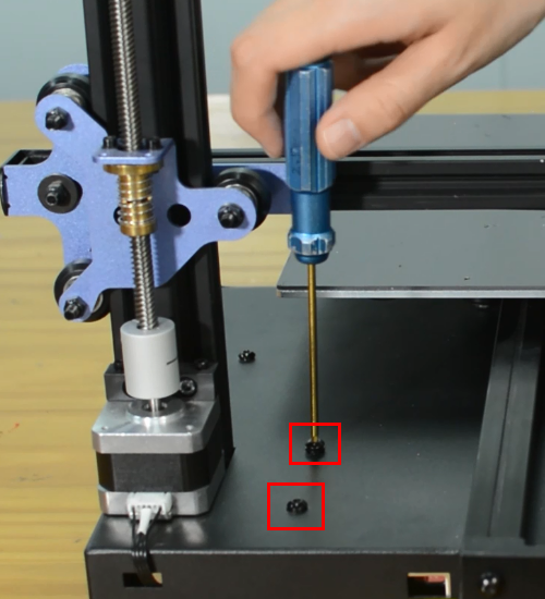
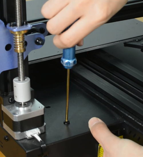
Release and remove the two screws that secure the PSU.
Remove the bottom cover, unplugging the cooling fan.
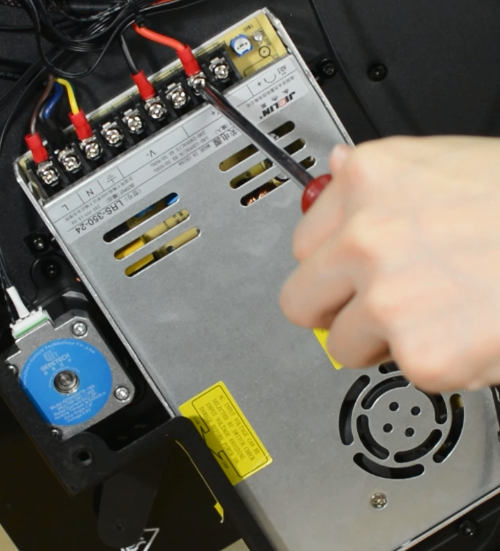
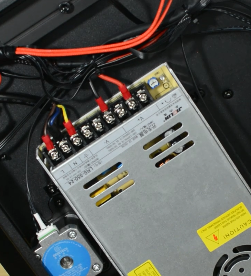
Using a Philips screwdriver release all five screws.
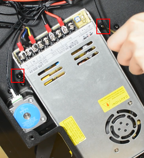
Release and remove the two screws that holding the PSU and make sure you hold it before releasing the last screw.
Assembling the new PSU.
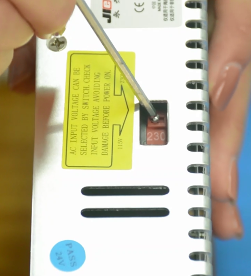
Ensure that the DIP switch of the power supply is adjusted to the right voltage!
Please triple-check you have connected the cables correctly!
There is a risk of damaging the PSU or the printer itself, if the cables are connected incorrectly or not tightened properly!
Tighten the two screws.
Plug the cooling fan back in and secure the base cover with screws.
How to replace a hotbed
| Tools necessary for this guide |
|---|
| Allen keys – 3 mm
Flat screwdriver tip width 2.5 mm Diagonal pilers Zip ties |
Turn the printer off and unplug it from the socket.
Remove the bottom cover, unplugging the cooling fan.
Disconnect the hotbed cable and hotbed thermistor.
Release and remove the three screws of the Y-axis rail.
Remove the hotbed from the printer.
Install the new hotbed kit and pay attention to how the Y-axis belt is installed.
Tighten the three screws.
Connect the hotbed thermistor and hotbed cable.
Plug the cooling fan back in and secure the base cover with screws.
How to replace a screen
| Tools necessary for this guide |
|---|
| Allen keys - 2.5/3 mm |
