Wireless temperature and humidity sensor with RF modules
wireless temperature and humidity sensor with RF modules Arduino has been extensively used for home automation, it is more flexible and cheaper than commercial solution. With varieties of projects out there, Arduino has bring custom home automation to everyday life. Ranging from a phone application that alert you to pakage your diliveries to a solar powered wireless radiation monitor by Geiger counter measuring the background radiation outside the house and transmit it to a display monitor inside the house. Similar application is much more.
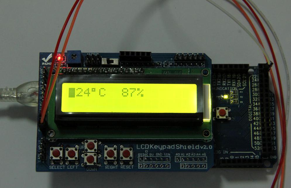
This time I would built up a wireless temperature and humidity sensor with RF modules. Transmitter station that can be placed anywhere you want to monitor collects the temperature and humidity data and transmit it to receiver station. Receiver station receives data from transmitter and displays it on 16X2 LCD Keypad shield.
Basic requirement: Arduino Uno ( this will be the transmitter with DHT11 sensor attached) Arduino IO Expansion Shield DHT11 Temparature & Humidity Sensor Arduino Mega (this will be the Receiver with LCD display attached) 16X2 LCD keypad shield 433Mhz RF Transmitter 433Mhz RF Receiver
 First of all, let’s get a tough idea of RF module and how it works. Comparing with Xbee, RF module is the cost-effective wireless device for remote control and data transmission, as the name suggests, the RF module operates at Radio Frequency. The corresponding frequency range varies between 30 kHz & 300 GHz. In this RF system, the digital data is represented as variations in the amplitude of carrier wave. This kind of modulation is known as Amplitude Shift Keying (ASK).
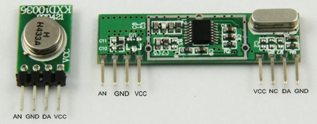
This RF module comprises of an RF Transmitter and an RF Receiver. The transmitter/receiver (Tx/Rx) pair operates at a frequency of 433 MHz. An RF transmitter receives serial data and transmits it wirelessly through RF through its antenna connected at pin4. The transmission occurs at the rate of 1Kbps- 10Kbps.The transmitted data is received by an RF receiver operating at the same frequency as that of the transmitter.
Transmitter Station:
 DHT11 sensor is basic and cheap device for hobbyists who want to do some data logging, which is good for 0-50C temperature and 20-80% humidity with 2-5% accuracy. Pin S on the DH11 breakout is connected to Arduino Uno pin 2. More details and DHT11 library please visit previous blog and wiki page.
In preparation to use the RF module, another library needs to be installed – the virtual wire. In this library, data pin on RF transmitter breakout is connected to digital pin 12 on Arduino for data transmission by default. However, to meet your demand , this default pin also can be re-assigned using function vw_set_tx_pin().
Receiver Station:
 The LCD Keypad shield is developed for Arduino compatible boards, to provide a user-friendly interface that allows users to go through the menu, make selections etc. It consists of a 1602 LCD. The keypad consists of 5 keys — select, up, right, down and left. LCD4Bit_mod library needs to be installed for this LCD keypad.
Data pin on the RF receiver module is connected to digital pin11 on Arduino by default for receiving data. As a result of mounting the LCD keypad shield, all of the space available is occupied on Uno, on Arduino Mega, the default data receiving pin 11 on Mega is also covered by LCD shield’s considerable bulk. The defualt pin needs to be modified for digital pin22 using vw_set_rx_pin() function.
There are two methods for expanding the range and efficiency of these two devices. Each transmitter device has a supply voltage range of 2 – 12 volts. The higher the voltage, the stronger the signal strength. Also, the use of an optional antenna will increase the effectiveness of your wireless communication. A simple wire will do the trick, with different antenna shapes and configurations based on the shape make of your project for best results.
