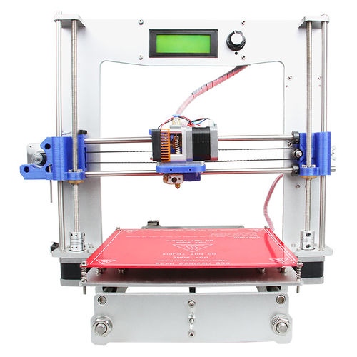
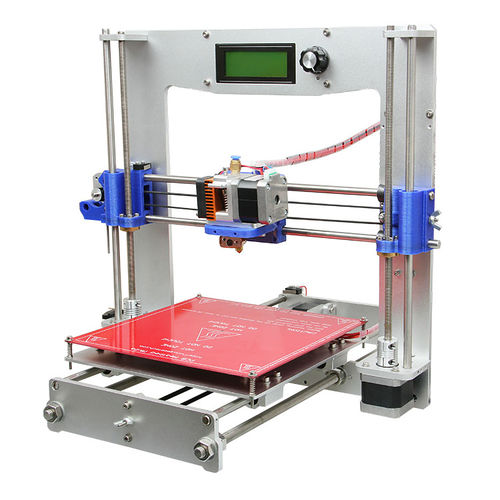
Aluminium Prusa i3
Contents
Introduction
This Aluminum Prusa I3 3D Printer is modified and manufactured by Shenzhen Getech Co., Ltd., based on Prusa i3. With features of extremely simple assembly, easy debugging and more stable performance, the Aluminum Printer is an ideal reference for you. The new frame is made from aluminum for durability and extending service life. In addition, a LCD panel is added as an integrated component of the printer, setting in the front top frame. In sum, this Aluminum Prusa I3 3D Printer DIY kit offers a significant experience for you to learn 3D printing from scratch, this kit that includes all the parts you need to build your first 3D printer will be the best valued purchase for you. If you are a starter, we have manuals and videos for step-by-step assembly and an active support service via forum to help with any queries you might have.
Improved Features
- Simplified structure means super fast assembly and easy adjustment.
- 6mm -thickness aluminum chasis for high strength and durability.
- In-built LCD control panel for easy operating, SD Card Reader support stand-alone printing
- Standard printing area: 200 x 200 x 180 mm.
- Multi filaments compatibility: PLA, ABS, Nylon, Wood and Flexible PLA.
- Constructed with MK8 extruder to provide high-resolution printing.
- No soldering required for assembly.
Specifications
Printing specifications:
Print technology: Fused Filament Fabrication
Build volume: 200 x200x180mm
Layer resolution: 0.1-0.3mm
Positioning Precision: 0.1-0.3mm
Filament diameter: 1.75mm
Nozzle diameter: 0.3mm, 0.35 mm,0.4mm
Filament type: ABS/ PLA/Nylon Filament/Flexible PLA/Wood
Software:
Operating system: Windows/Mac/Linux
Control software: Repetier-Host, Printrun
File format: .STL , G-code
Temperature:
Max heated bed temperature: about 110°C
Max extruder temperature: about 240°C
Electrical:
Power supply:
Input: 110V/4.8A 220V/2.4A
Output:DC12V/15A
Connectivity: USB, SD card (support stand-alone printing)
Mechanical:
Body: aluminum plate of 6 mm thickness (silver-grey)
Build Platform: Borosilicate glass + Aluminium plate
XYZ Rods: Wear-resistant, stainless steel
Stepper Motors: 1.8° step angle with 1/16 micro-stepping
Physical structure: Reprap
Physical dimensions:
Machine size: 450x380x435mm
Shipping box: 520 x 420 x 230 mm
Net weight: 7.2 kg
Shipping weight: 9.5kg
building instruction
Assemble Y axis
Assemble the 2 threaded rods.
| Required parts | Required number | Part ID |
|---|---|---|
Thread the nuts and washers into the two M10 threaded rods separately. The orders should be:
1) Thread theY plate connecting plate in the middle.
2) Thread the M10 washer > spring washer >M10 nut > M10 nut > M10 washer on the left
Thread theM10 washer < spring washer < M10 nut < M10 nut< spring washer < M10 washer on the right
https://www.youtube.com/watch?v=KCKfAqoxRZg&index=1&list=PLODCkot3GriiomwOYGZslsb_DPNh3KWgj
Attach the front and rear side support plates of the rods.
| Required parts | Required number | Part ID |
|---|---|---|
Slide assembled threaded rods into the side support plates. Screw up the rods and plates with 4 M10 nuts and M10 washers.
- Tips:the Y-axis must be a rectangle, that is the rods on both side should be parallel, so is the front and rear plate. Otherwise it will cause obstruction for the belt later.
https://www.youtube.com/watch?v=kNjxrcxLj8Y&index=2&list=PLODCkot3GriiomwOYGZslsb_DPNh3KWgj
Assemble the Y idler
| Required parts | Required number | Part ID |
|---|---|---|
Step1. Amount guide block A and B onto the front support plate together, screw up it with 2 M3x25 screws, M3washers and M3 nuts.
Note: the guide block B is close to front support plate.
Step2. Thread a M3 x25screw and M3washer through the bearing holder.
Step3. Put a M4 x25screw and M4wsaher through the holes with the two 624ZZ bearings in between. Lock the other end with a M4 lock nut. You may need a spanner to tighten locknut.
Step4. Mount the assembled bearing holder through the guide blocks onto the front support plates. And screw it with a wing nut.
- Please leave enough room for the belt between the ball bearing and the screw.
https://www.youtube.com/watch?v=PPit5h9UuUw&list=PLODCkot3GriiomwOYGZslsb_DPNh3KWgj&index=3
Mount the Y motor
| Required parts | Required number | Part ID |
|---|---|---|
Step1. Mount the pulley on the motor shaft, one of the screws should be screwed on the cross section of the shaft. Screw it up tightly.
Step2. Insert the motor block into the slot; you may need to use a little strength to do this. Then screw the motor on the Y motor fix plate with 3 M3 x 10 screws and M3washers
Step3. Fix the block plate with 2 M3 x 16 screws and M3 washers.
https://www.youtube.com/watch?v=VeoF0Rgubg0&index=4&list=PLODCkot3GriiomwOYGZslsb_DPNh3KWgj

