Arduino 7 segment LED timer with 74HC595 module
This time I will made a simple timer which can count up and count down from 0 to 99 using 7 segment LED and 74hc595 shift and register breakout board. Using more 7 segment LED and 74hc595 module can accomplish multi-digit timer counting up and counting down if you wish.
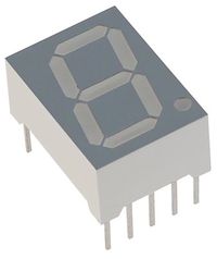
A 7-segment display consists of eight LEDs arrange to form the digit eight, with a decimal point. Individually on or off, they can be combined to produce simplified representations of the Arabic numerals. Often the seven segments are arranged in an oblique (slanted) arrangement, which aids readability. In most applications, the seven segments are of nearly uniform shape and size.
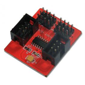
There are 10 pins on the seven segments LED, which almost exhaust all socket on Arduino UNO. If two or more 7 segment LEDs is connected, the sockets on Arduino is not enough. In such a situation we could extend it by utilizing 74hc595 breakout board.
The datasheet refers to the 74HC595 as an "8-bit serial-in, serial or parallel-out shift register with output latches; 3-state." In other words, you can use it to control 8 outputs at a time while only taking up a few pins on your micro-controller. You can link multiple registers together to extend your output even more.
In brief, If we use our Arduino to send a decimal number(0-255) out through a digital pin to the 74hc595, it will convert it to binary and set the matching output pins high or low. In this method, we can send a specific decimal number to light up LED parts for constituting a whole number.
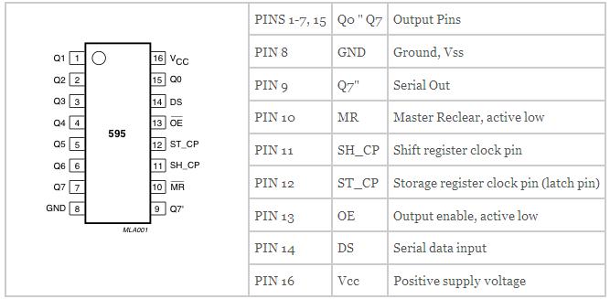
Pins Q0~Q7 are the output pins that we want to control. The Q7' pin is serial out. 74hc595 pin 14 is the data pin, 12 is the latch pin and 11 is the clock pin. The data pin connects to a digital output pin on the Arduino. The latch pin is like a switch, when it is low the 74hc595 will accept data, when it is high, the 74hc595 goes deaf. The clock pin is toggled once the data has been received. So the procedure to get the data into a 74hc595 is this:
1) set the latch pin low (pin 12) 2) send the byte of data to the 74595 (pin 14) 3) toggle the clock pin (pin 11) 4) set the latch pin high (pin 12)
Pin 10 (reset) is always connected to the +5V, pin 13 (output enable) is always connected to ground. Thankfully there is a command that has parts 2 and 3 in one; you can use digitalWrite(); to take care of the latch duties. The command shiftOut(); is the key. The syntax is:
shiftout(a,b,c,d);where:
a = the digital output pin that connects to the 74595 data pin (14); b = the digital output pin that connects to the 74595 clock pin (11); c = can be either LSBFIRST or MSBFIRST. MSBFIRST means the 74595 will interpret the binary number from left to right; LSBFIRST will make it go right to left; d = the actual number (0~255) that you want represented by the 74595 in binary output pins.
So if you wanted to switch on pins 1,2,5 and 6, with the rest low, you would execute the following:
digitalWrite(latchpin, LOW); shiftOut(datapin, clockpin, MSBFIRST,102); digitalWrite(latchpin, HIGH);
Because the lack of single 7 segment LED, I have to take a 4-digit 7segment at hand instead, just light up one digit of four. The principle of them is almost same in general. Since not all the 7 segment LED is same, so we must work out which pin for which segment using multimeter. Then find out appropriate binary number to represent the high or low level to these pins and convert it to decimal number sending to 74hc595.Schematic wiring diagram is below.
Relevant code
/*
Using 2 7-segment displays with the 74HC595 shift registers
CC by-sa-nc 3.0
http://tronixstuff.wordpress.com
 */
int latchpin = 8; // connect to pin 12 on the '595
int clockpin = 12; // connect to pin 11 on the '595
int datapin = 11; // connect to pin 14 on the '595
float b = 0;
int c = 0;
float d = 0;
int e = 0;
int speed = 300; // used to control speed of counting
int segdisp[10] = {
 3,159,37,13,153,73,65,27,1,9 };
void setup()
{
 pinMode(latchpin, OUTPUT);
 pinMode(clockpin, OUTPUT);
 pinMode(datapin, OUTPUT);
}
void loop()
{
 //  Count up
 for (int z=0; z<100; z++)
 {
   digitalWrite(latchpin, LOW);
   shiftOut(datapin, clockpin, LSBFIRST, 0); // clears the right display
   shiftOut(datapin, clockpin, LSBFIRST, 0); // clears the left display
   digitalWrite(latchpin, HIGH);
   if (z<10)
   {
     digitalWrite(latchpin, LOW);
     shiftOut(datapin, clockpin, LSBFIRST, segdisp[z]); // sends the digit down the serial path
     shiftOut(datapin, clockpin, LSBFIRST, 255); // sends a blank down the serial path to push the digit to the right
     digitalWrite(latchpin, HIGH);
   }
   else if (z>=10)
   {
     d=z%10; // find the remainder of dividing z by 10, this will be the right-hand digit
     c=int(d); // make it an integer, c is the right hand digit
     b=z/10; // divide z by 10 - the whole number value will be the left-hand digit
     e = int(b); // e is the left hand digit
     digitalWrite(latchpin, LOW); // send the digits down to the shift registers!
     shiftOut(datapin, clockpin, LSBFIRST, segdisp[c]);
     shiftOut(datapin, clockpin, LSBFIRST, segdisp[e]);
     digitalWrite(latchpin, HIGH);
   }
   delay(speed);
 }
 delay(2000);
 //  Count down
 for (int z=99; z>=0; z--)
 {
   digitalWrite(latchpin, LOW);
   shiftOut(datapin, clockpin, LSBFIRST, 0); // clears the right display
   shiftOut(datapin, clockpin, LSBFIRST, 0); // clears the left display
   digitalWrite(latchpin, HIGH);
   if (z<10)
   {
     digitalWrite(latchpin, LOW);
     shiftOut(datapin, clockpin, LSBFIRST, segdisp[z]); // sends the digit down the serial path
     shiftOut(datapin, clockpin, LSBFIRST, 255); // sends a blank down the serial path to push the digit to the right
     digitalWrite(latchpin, HIGH);
   }
   else if (z>=10)
   {
     d=z%10; // find the remainder of dividing z by 10, this will be the right-hand digit
     c=int(d); // make it an integer, c is the right hand digit
     b=z/10; // divide z by 10 - the whole number value will be the left-hand digit
     e = int(b); // e is the left hand digit
     digitalWrite(latchpin, LOW); // send the digits down to the shift registers!
     shiftOut(datapin, clockpin, LSBFIRST, segdisp[c]);
     shiftOut(datapin, clockpin, LSBFIRST, segdisp[e]);
     digitalWrite(latchpin, HIGH);
   }
   delay(speed);
 }

   delay(2000);
}
Details reference tronixstuff.com


