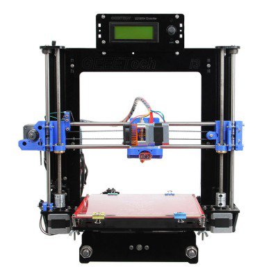
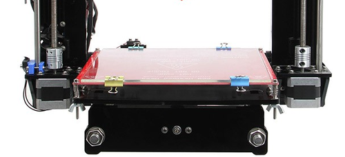
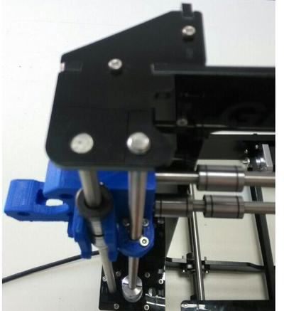
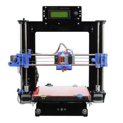
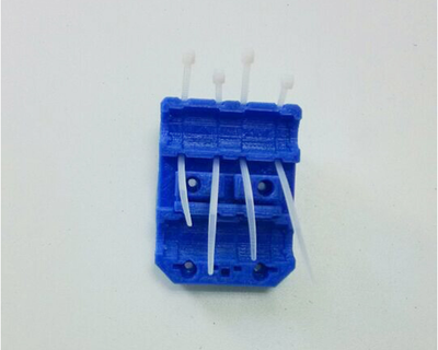
Assemble Manual of Geeetech Acrylic Prusa I3 (5mm)
Prologue Note: This manual only applies to the 5-mm acrylic Prusa I3. We have another one that is 8-mm.
As picture is much more helpful than words in assembly manual, so I use plenty of pictures and less word.
Unfold the package and take all the parts out to check the condition of the items.
Contents
- 1 Assemble Y axis (the bottom part of the chassis)
- 2 Assemble Y - Z axis
- 3 Assemble the right and left side panel
- 4 Assemble the Z axis (the vertical axis)
- 5 5Assemble the X axis (the horizontal axis)
- 6 Mount the extruder on the X axis
- 7 Mount the end stops
- 8 Mount the LCD panel frame
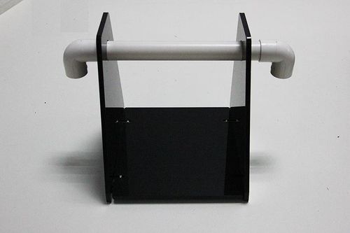
- 9 Mount the filament spool
- 10 mount the control board on the left side panel
- 11 Mount the PSU on the right side panel
- 12 Wiring
Assemble Y axis (the bottom part of the chassis)
1.1Assemble the rods of a Y axis
| Required parts | Part ID |
|---|---|
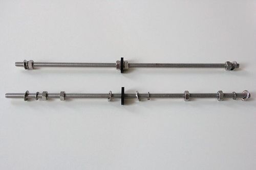
Step1. Assemble the threaded rod
- Thread the nuts and washers on the two M10 threaded rods separately. The order should be:
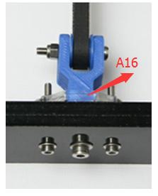
- M10 washer > M8 spring washer M10 screw > M10 screw > M10 washer > >A 12> M10 washer > M8 spring washer > M10 screw > M10 screw > M8 spring washer > M10 washer
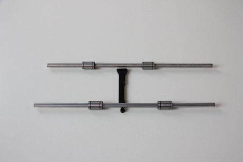
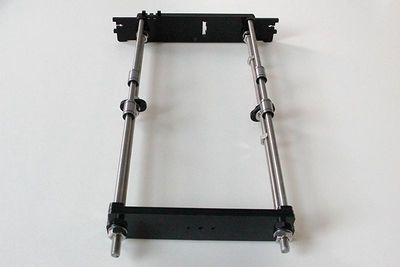
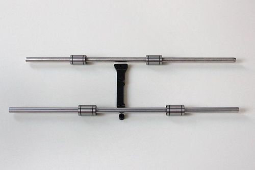
Step2. Assemble the Y axis smooth rod
- Slide 2 bearings on each smooth rod. Before you slide the bearings please make sure they are clean. (Ignore the black one in between)
| Required parts | Part ID |
|---|---|
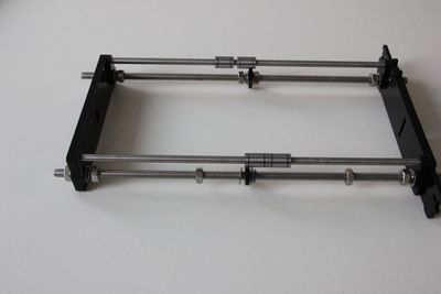
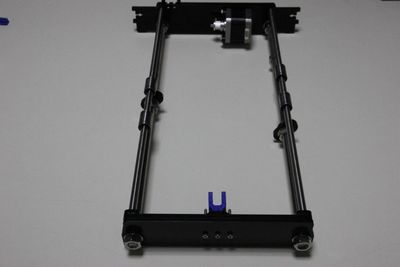
Attach the front and rear Acrylic support plates of the rods
| Required parts | Part ID |
|---|---|
Assemble the Y idler
| Required parts | Part ID |
|---|---|
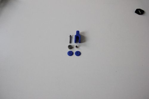
Step1. put the M4 X 25 screw into the end of the Y idler, from outside to inside, and screw it up with a M4 nut.
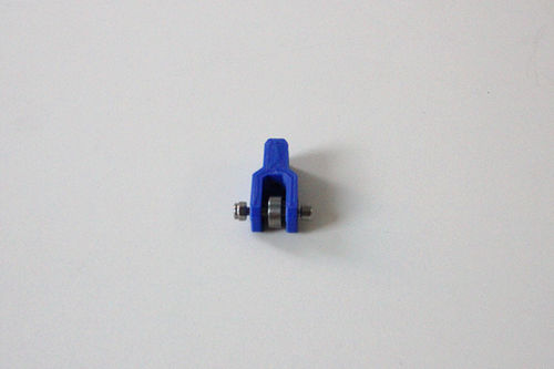
Step2. Put the screw through the printed Y idler piece, with the 624ZZ bearings in between. Lock the other end of a M3 nut.
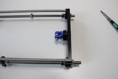
Step2. Mount the assembled idler onto the front support plates.
Mount the Y motor
| Required parts | Part ID |
|---|---|
build the printing platform
| Required parts | Part ID |
|---|---|
Step1. Mount the belt mount on the bottom side of the plate.
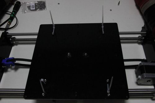
Step2. Get the build platform plate zip-tied to the 4 linear bearings.
Step3. Attach he heated bed.
| Required parts | Part ID |
|---|---|
The circled part need soldering.
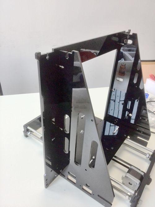
Assemble Y - Z axis
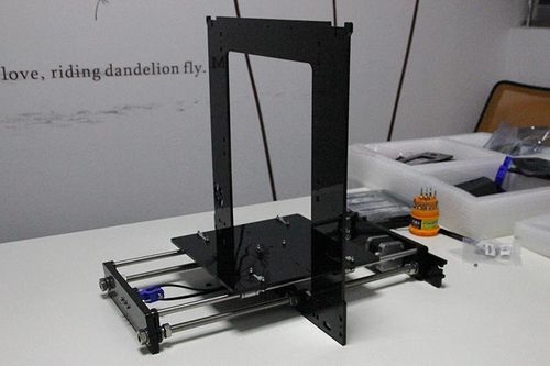
The main frame is held upright after the acrylic fender washers on the Y axis threaded rods. The front of the plate should be sticking out a lot further than the back.
Assemble the right and left side panel
| Required parts | Part ID |
|---|---|
Mount the rear part of the Y axis and the side panel together.
| Required parts | Part ID |
|---|---|
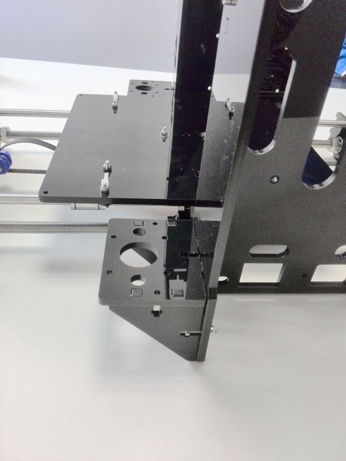
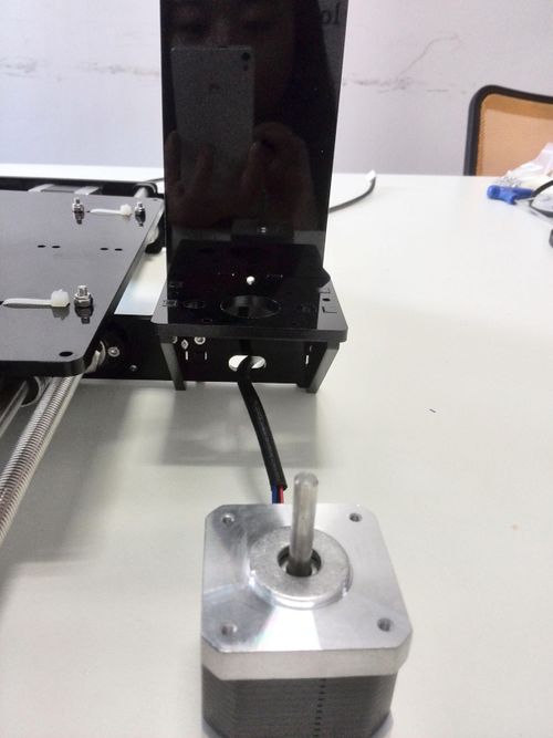
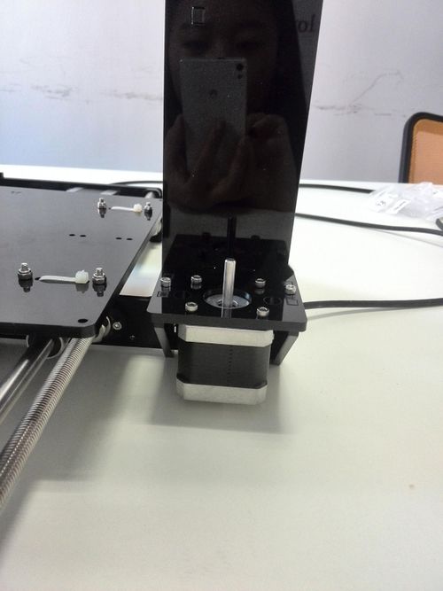
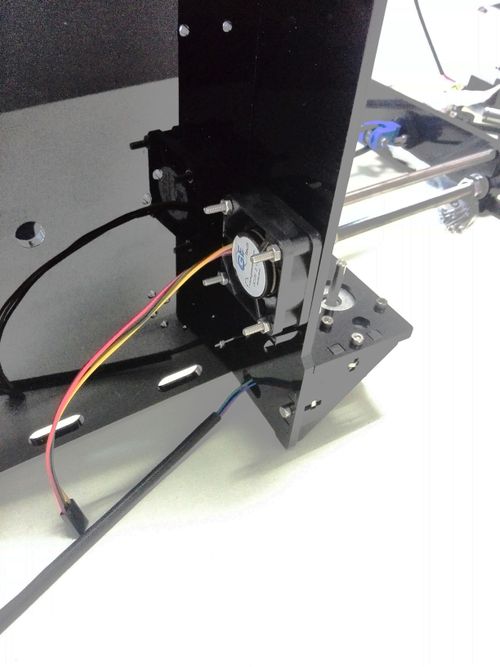
Assemble the Z axis (the vertical axis)
Step1. Assemble the Z-axis bottom mounts
| Required parts | Part ID |
|---|---|
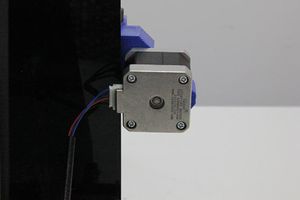
Assemble the 2 Z motors
Mount the fan on the left side
| Required parts | Part ID |
|---|---|
5Assemble the X axis (the horizontal axis)
Step1. Assemble the X-Axis Idler
Put the screw through the printed Y idler piece, with the 624ZZ bearings in between. Lock the other end of a M3 nut.
| Required parts | Part ID |
|---|---|
Step2. Mount the idler into the following part
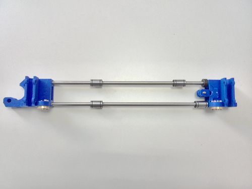
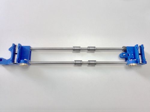
Step3. Assemble the 2 smooth rods.(380 mm)
- Slide 2 bearings on the each rod as shown in the picture.
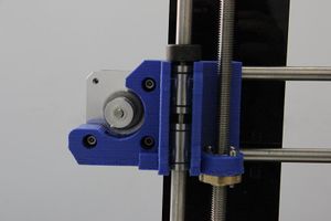
Slide the X-axis motor-end and the idler-end onto both ends of the smooth rods. The X-axis motor-end is on the left and the idler-end on the right. This is going to take some force, or you can use file to make the holes lager.
Mount the brass nut on the following part.
Insert the rest bearings into the bracket of both end of the smooth rod.
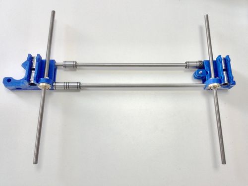
Thread the threaded rod through the following part. It would be easier to do it now.
Mount the aluminum plate under the extruder.
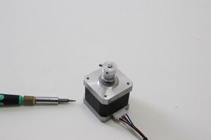
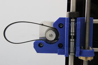
Fix the two pulleys on both if the threaded rod. And plug it on the motor shaft.
Assemble the X-Z axis.
| Required parts | Part ID |
|---|---|
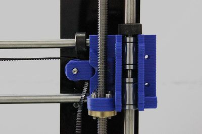
Step1. thread the X-axis through the Z axis.
Step2 assemble the top mount of the Z-axis.
Mount the extruder on the X axis
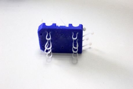
step1. Thread the zip-tie through the extruder bracket.
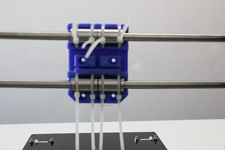
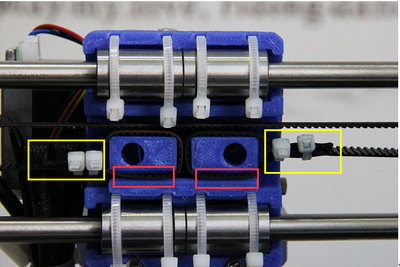
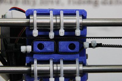
Step2. Mount the extruder bracket on the smooth rod and insert the two bearings into the bracket. Tie up the Y belt then.
Step3. Amount the extruder support.
Step4. Mount the extruder
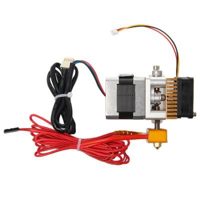
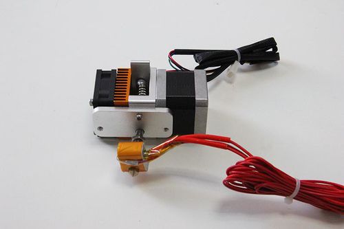
This is the fully assembled MK8 extruder.
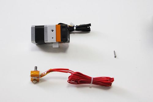
Take the nozzle part and the bolt out.
| Required parts | Part ID |
|---|---|
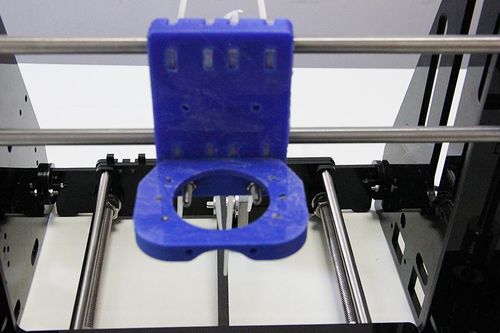
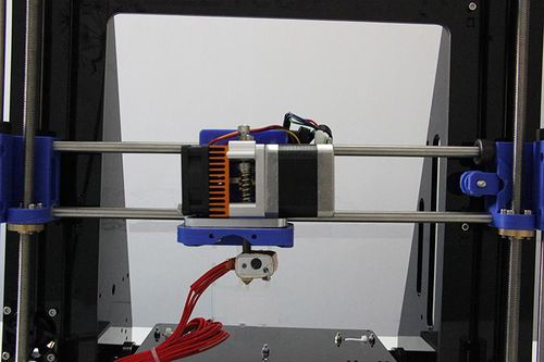
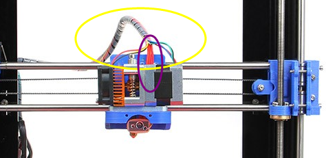
Fix the assembled extruder on the blue part. Pay attention to the direction of the motor and the fan.
Pay attention to the exit of the red wire, it will affect the final wiring steps.
Mount the X-axis motor
Assemble the belt.
Pay attention to the tooth mesh of the belt and the part in red circle.
Mount the end stops
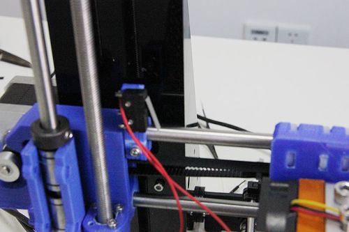
End stop of X-axis
| Required parts | Part ID |
|---|---|
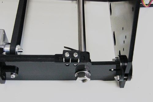
End stop of Y-axis
| Required parts | Part ID |
|---|---|
Note the direction of the switch.
End stop of Z-axis
| Required parts | Part ID |
|---|---|
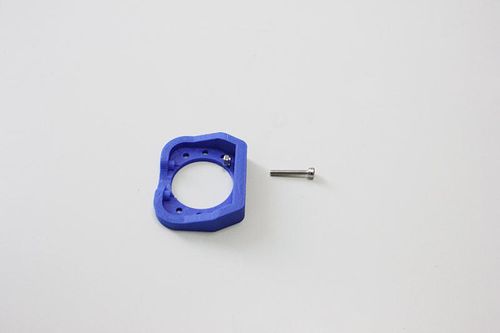
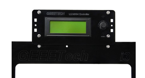
Mount the LCD panel frame
Mount the filament spool
So far, the framework of the 3D printer is almost finished.
mount the control board on the left side panel
Ramps 1.4 + Mega 2560 + A4988
Stack the Ramps 1.4on the Mega 2560 and plug the 5 A4988 on the Ramps 1.4.
Sanguinololu
Plug the 5 A4988 on Sanguinololu
Mount the PSU on the right side panel
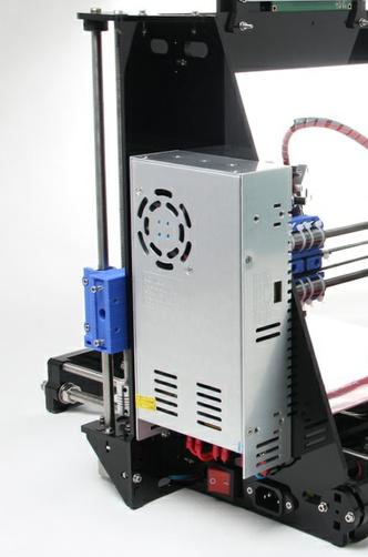
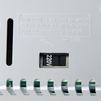
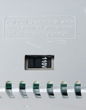
Pay attention to the switch on the right side of the PSU, there are two options of voltage: 110 V and 220V, choose according the standard in your country.
Wiring
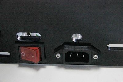
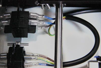
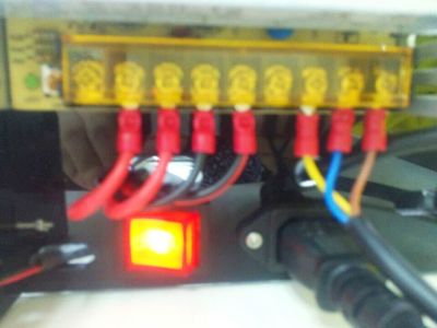
PSU wiring
Do make sure you connect the wires correctly, otherwise it may lead to damage to the control board and the PSU.
control board wiring
1)The referring wiring schematic diagram of Ramps 1.4
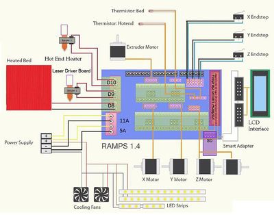
For more information about ramps 1.4, please visit the ramps 1.4 wiki.
2) The referring wiring schematic diagram of Sanguinololu
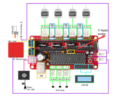
For more information about Sanguinololu, please visit the wiki page.
Note: when connect the other Y-motor, use the 4-pin M-F DuPont cable and pay attention to the directions of the wire. If you connect them reversely, the 2 Z motor will move in different directions.
Look at the colors of the wire.
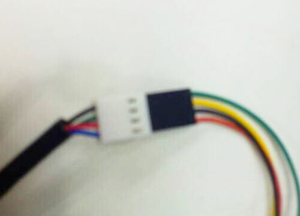
All the wires can be tied together under the printer, but you should make sure they don’t touch the belt.
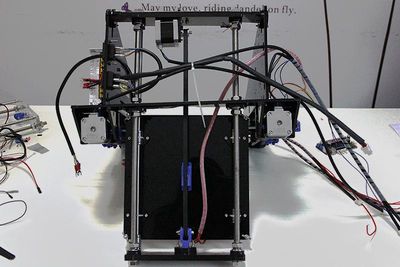
The whole printer assembly work is already done.
Next is the testing and debugging.
