DHT 11 Humidity & Temperature Sensor
Contents
Introduction
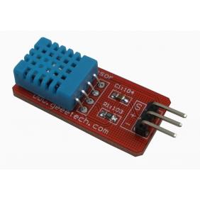
This DFRobot DHT11 Temperature & Humidity Sensor features a temperature & humidity sensor complex with a calibrated digital signal output. By using the exclusive digital-signal-acquisition technique and temperature & humidity sensing technology, it ensures high reliability and excellent long-term stability. This sensor includes a resistive-type humidity measurement component and an NTC temperature measurement component, and connects to a high- performance 8-bit microcontroller, offering excellent quality, fast response, anti-interference ability and cost-effectiveness.
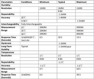
Technical Specifications:
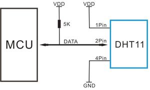
Typical Application
Note: 3Pin – Null; MCU = Micro-computer Unite or single chip Computer When the connecting cable is shorter than 20 metres, a 5K pull-up resistor is recommended; when the connecting cable is longer than 20 metres, choose a appropriate pull-up resistor as needed.
Power and Pin
DHT11’s power supply is 3-5.5V DC. When power is supplied to the sensor, do not send any instruction to the sensor in within one second in order to pass the unstable status. One capacitor valued 100nF can be added between VDD and GND for power filtering.
Communication Process: Serial Interface
Single-bus data format is used for communication and synchronization between MCU and DHT11 sensor. One communication process is about 4ms. Data consists of decimal and integral parts. A complete data transmission is 40bit, and the sensor sends higher data bit first. Data format: 8bit integral RH data + 8bit decimal RH data + 8bit integral T data + 8bit decimal T data + 8bit check sum. If the data transmission is right, the check-sum should be the last 8bit of "8bit integral RH data + 8bit decimal RH data + 8bit integral T data + 8bit decimal T data".


