IOIO-OTG
Introduction
The IOIO–OTG is a printed circuit board specially designed to work with the Android device or PC application. With it, you can connect an app on an Android device or a PC to low level peripherals like PWM, GPIO, ADC, I2C, UART and SPI. The IOIO doesn’t require you to write two pieces of software (board and client), it only require you to write the client-side (Android, PC) software. You can use a high-level programming language (currently Java) with a rich and intuitive API that allows you to manipulate the I/O pins and hardware peripherals on the board. So it is so fast and simple to do some prototyping and development with the IOIO. And this must be attributed to its microcontroller – PIC24FJ256GB206. Unlike the previous IOIO boards, IOIO–OTG can leverage the USB On-The-Go specification to connect as a Host or as a device. The IOIO-OTG acts as a USB Host and supply charging current if the app is running on your Android device while it assumes Device mode and present itself as a virtual serial port if app is running on a Windows, Linux or OSX machine. The IOIO-OTG is all open-source, software, firmware and hardware. The development has been an ongoing process, with new features and bug fixes introduced on a regular basis. New versions of firmware are distributed in a way that makes it very simple for the user to upgrade: connect the IOIO-OTG to a PC and run a simple program to flash the latest version or your own custom one if you're into such adventures. Notes: Avoid powering your IOIO-OTG with 10V over long wires or your board may fail.
Overview
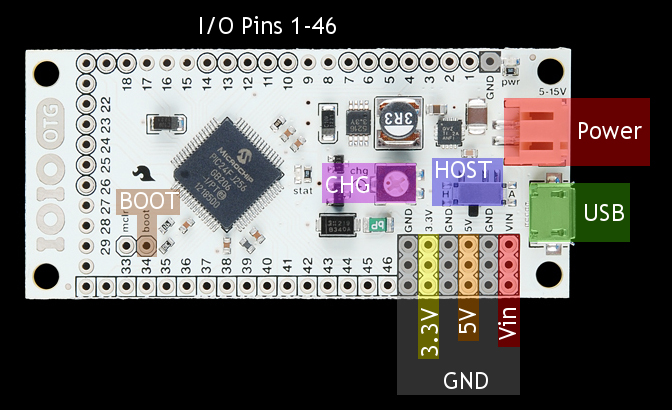
The IOIO-OTG board contains the following components:
- USB connector (micro-AB, female): Used to connect to host computer, an Android device or a Bluetooth dongle.
- Power jack (2-pin JST, female): Used for power supply to the board. Voltage between 5V-15V should be supplied.
- GND pins (10 pins): Ground connection.
- VIN pins (3 pins): Used for outputting the supply voltage to your circuit, or as an alternative input to the power jack.
- 5V pins (3 pins): 5V output from the on-board regulator, which can be used in your circuit.
- 3.3V pins (3 pins): 3.3V from the on-board regulator, which can be used in your circuit.
- I/O pins (46 pins, numbered 1-46): General purpose I/O pins. Some have special functions, see below.
- PWR LED (red): Lights when the IOIO is getting power.
- STAT LED (yellow): General purpose on-board LED, under application control.
- MCLR pin: Not normally used. Its purpose is for programming new bootloader firmware on the IOIO board.
- BOOT pin: Special pin used for getting the IOIO into bootloader mode on power-up. Note that this pin is shared with the stat LED.
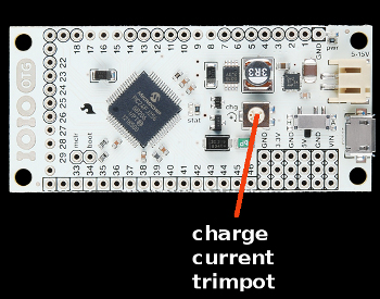
- Charge current trimmer (CHG): Adjusts the amount of current supplied on the VBUS line of the USB when acting as a USB host. Typically used in battery-powered application with Android to prevent the Android from draining the battery quickly. Turning in the (+) direction increases charge current.
- Host switch: In "A" mode, the IOIO-OTG will detect whether it should act as host or as device automatically, according to whichever USB connector is plugged in (micro-A or micro-B). To support non-standard USB cables or adapters that use micro-B type, move the switch to the "H" position to force host mode.
I/O Pins
The I/O pins are the essence of the IOIO. They are used to connect to external circuits using different interfaces. The common denominator to all pins is that they can all serve as 3.3V digital inputs or 3.3V digital outputs. In addition, many of the pins are capable of other functions as detailed in the table at the bottom of this page. For convenience, the common pin functions are presented graphically on the bottom of the board, with a legend:
- Pins surrounded by a square can be used as analog inputs (3.3V). For more details, see Analog Input.
- Pins surrounded by a circle are 5V-tolerant, i.e. can be used as 5V logic inputs or product 5V logic output when used in open-drain mode with the help of a pull-up resistor. For more details, see Digital I/O.
- Pins marked with "P" can be used as peripheral inputs and outputs. Mainly, this includes PWM, Pulse Input, UART, and SPI.
- The pin marked with "Pi" can be used as peripheral input (but not output).
- Pins marked with DAx and CLx are used for TWI.
Beginner Guide
The programming language used to write an Android app is Java. If you are not familiar with Java, this tutorial will only go over writing a simple Java app using the IOIO library. This tutorial will not cover how to write Java code nor will it cover how to use the rich features within your Android device, like GPS, accelerometer, touch screen, etc. Once you get to the point where you want to use the vast array of features on your Android, we suggest first looking at the [technical resource][1] section on developer.android.com. If you still can't find the examples you are looking for, simply browsing the web will result in a ton of information and examples that show you how to communicate with all of the great pieces of hardware within your Andriod device.
In general, the holy grail for developing Android apps is developer.android.com. There, you will find most of the information on Android development. For documentation/downloads specific to the IOIO and for more advanced discussions about the IOIO, see these links:
- IOIO-OTG Wiki
- All of the Downloads you need
- IOIO discussion group
- Gathering Your Hardware
Here are the pieces of hardware you will need to complete this tutorial:
- Android enabled device using OS 1.5 or greater
- IOIO-OTG board, with adapter cable
- USB cable that is compatible with your Android device
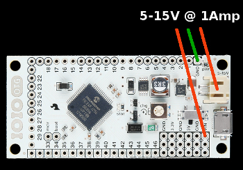
- 5-15V power supply with at least 1A of current. You will need to power the IOIO through the VIN and GND pins or there is an optional JST connector, which can be used with this adapter and wall wart power supply. More information at the end of the tutorial found here.
- Installing the Development Environment
The Eclipse IDE (integrated development environment), the Android SDK (software development kit), and the JDK (Java development kit) are the primary pieces of software that you will need to install. The page developer.android.com has written thorough instructions on what exactly you will need to download. Please read the instructions carefully, they are found in the link below:
Installing Eclipse and the Android SDK ATTENTION: You must use JDK v6 (not v5 or v7) for Android development.
If you have any problems, see the Troubleshooting section from developer.android.com.
When you reach Step 4 in the Android SDK tutorial, you will at least need to install the SDK components relevant to the Android device you will be working with. For example, if you have an Android phone, goto Settings > About Phone and scroll down to Android Version. You must install the SDK platform corresponding to the Android version of your device.
- Import the HelloIOIO Example
Instead of creating a new project from scratch, we can import an existing IOIO project that has all of the files ready to go. If you need instruction on creating a new project, see the Hello World example on developer.android.com.
To import an existing project...
1) Download the latest 'Android Software and IOIO Application Firmware Image' zip file (App-IOIOxxxx, where xxxx is the software/library version number).
Note: If you are using an older IOIO board, make sure the version number of your IOIO library is less than or equal to the version number of your firmware. In other words, if you can't get the sample app to work with an older IOIO, use one of the older library versions or upgrade the firmware on your IOIO using the IOIO Manager and then use the latest download.
2) Unzip the downloaded package into a safe location where you want to keep your project files.
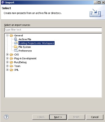
3) Next, open Eclipse, then goto File > Import, and select Existing Projects Into Workspace. Then hit Next.
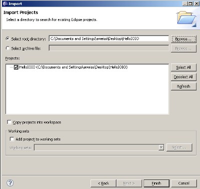
4) Another window will pop up (as shown below). Select 'Select Root Directory' and navigate to the file you just unzipped and point to the HelloIOIO folder found in /applications/HelloIOIO. Be sure the check box is selected for your project. Now hit Finish.
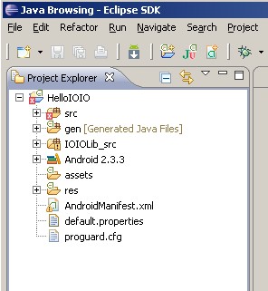
5) You should now have HelloIOIO in your project explorer in Eclipse. Notice that there is a small red x next to the project name. This means there are build errors, so whenever you see this, you know something needs to be fixed. In this situation, we need to link the IOIO library to our project, as outlined in the next step.
6) Now we need to link the IOIO library and IOIO Bluetooth library to your project which will give you full access to the IOIO API. The IOIOLib and IOIOLibBT directories contains the libraries that allow you to communicate to the IOIO board.
Follow the exact same steps in 3 and 4 above, except use the IOIOLib file and then the IOIOLibBT instead of the HelloIOIO file.
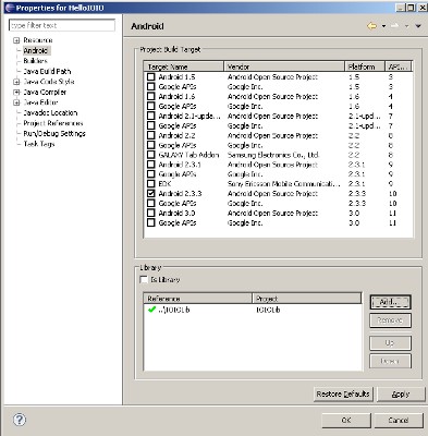
After you added the library files into the workspace, select the HelloIOIO project, then on the top toolbar goto: Project > Properties. Then, select 'Android' in the list to the left. In the 'Library' section, click add, then add both the IOIOLib and IOIOLibBT libraries. You should see both of them with a green check mark as shown below (note: image doesn't show the IOIOLibBT, but it should be there if using Bluetooth).
Also, make sure the 'Project Build Target' is properly selected according to the specific Android OS you are using.
Note: If you ever need to change your build target (say you are using a device with a different Android OS), you can change it here.
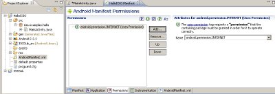
7) The next thing you need to do is make sure your app has internet permissions. To do this, open the AndroidManifest.xml file located in the main project tree. Make sure you are in the permissions tab, then click Add > Usage Permissions, then make sure the 'Name' field is android.permission.INTERNET. See the picture below for reference:
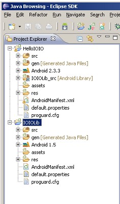
After you have done this and saved your project, the projects explorer window should look something like this:
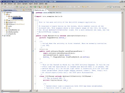
The project tree has many files. You really don't need to mess with the IOIOLib project tree so you can minimize that one. The file that contains the java code for the IOIO is in HelloIOIO > scr > ioio.examples.hello > MainActivity.java. Double click on the MainActivity.java file and you should see this:
Here you can start writing code and changing the HelloIOIO sketch. At this point you can keep reading or jump immediately to setting up your IOIO board and testing the app.
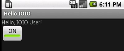
The MainActivity.java file contains the code that talks to the IOIO board. If you want to change the UI (user interface or graphics) of your app, the res > layout > main.xml file is where you make the changes. The main.xml file in the HelloIOIO example uses an interface that looks like this:
For more information on XML layouts, see the hello world example on developer.android.com, then scroll down to the 'Upgrade the UI to XML Layout' section.
At this point you should be ready to write your own Android IOIO app. You can now keep reading or jump immediately to setting up your IOIO board and testing the app.
- Troubleshooting Project Errors
Eclipse has the ability to compile your code in real time. When there is an error, you will see a red x somewhere in your project. This can mean many things. To figure out what the errors are, Eclipse has tab called 'Problems' that shows you what errors you are getting. This tab is usually found towards the bottom of the Eclipse window. Sometimes the error will tell you exactly what's wrong and sometimes the errors are more obscure.
If you are getting unknown errors in your project, please refer to the IOIO-OTG troubleshooting guide.
- The Example IOIO Sketch
After you have imported the HelloIOIO file and linked the IOIOLib file, you are ready to start writing code. The example sketch displays a toggle button on the screen, which enables control of the on-board LED. This example shows a very simple usage of the IOIO and will give you an idea of what to expect when programming.
The code in the MainActivity.java file is shown below.
  * our GUI.
   */
   @Override
   public void onCreate(Bundle savedInstanceState) {
       super.onCreate(savedInstanceState);
       setContentView(R.layout.main);
       button_ = (ToggleButton) findViewById(R.id.button);
   }
   /**
   * This is the thread on which all the IOIO activity happens. It will be run
   * every time the application is resumed and aborted when it is paused. The
   * method setup() will be called right after a connection with the IOIO has
   * been established (which might happen several times!). Then, loop() will
   * be called repetitively until the IOIO gets disconnected.
   */
   class IOIOThread extends AbstractIOIOActivity.IOIOThread {
       /** The on-board LED. */
       private DigitalOutput led_;
       /**
       * Called every time a connection with IOIO has been established.
       * Typically used to open pins.
       *
       * @throws ConnectionLostException
       *             When IOIO connection is lost.
       *
       * @see ioio.lib.util.AbstractIOIOActivity.IOIOThread#setup()
       */
       @Override
       protected void setup() throws ConnectionLostException {
           led_ = ioio_.openDigitalOutput(0, true);
       }
       /**
       * Called repetitively while the IOIO is connected.
       *
       * @throws ConnectionLostException
       *             When IOIO connection is lost.
       *
       * @see ioio.lib.util.AbstractIOIOActivity.IOIOThread#loop()
       */
       @Override
       protected void loop() throws ConnectionLostException {
           led_.write(!button_.isChecked());
           try {
               sleep(10);
           } catch (InterruptedException e) {
           }
       }
   }
   /**
   * A method to create our IOIO thread.
   *
   * @see ioio.lib.util.AbstractIOIOActivity#createIOIOThread()
   */
   @Override
   protected AbstractIOIOActivity.IOIOThread createIOIOThread() {
       return new IOIOThread();
   }
}
In the code above, there are plenty of comments that explain what each line does. This app is a great starting point for making sure your development environment and the IOIO board is working correctly.
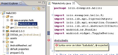
Eclipse is a very powerful tool and gives debugging information in real time. For instance, if you write code that doesn't make sense, Eclipse will show a red x next to the line in question and even give you suggestions as to how to change the line of code. Simply hover your mouse cursor over the line and you will see something like this:
Keep in mind, if you have errors, you will not be able to compile and run your code, you will need to fix any errors.
Also, the IOIOLib has thorough JavaDocs that can be generated and browsed via Eclipse. Goto Project > Generate Javadocs.
Here are some more resources to help you out with writing code:
- For all Android types, see the Android package index.
- For IOIO types and examples, see the IOIO-OTG Wiki.
- Compiling, Loading, and Running the App on Your Android Device
If you change any part of the code, simply saving the project compiles the program and creates a new HelloIOIO.apk file. An apk file is a compressed Android Package file, similar to zip and jar. files, that is used to create an app on your Android device. This file can be found in the HelloIOIO project tree within the bin directory.
Here are the steps to get the example app working on an N1 Android phone running the 2.3.3 platform.
1. Enable USB debugging. Settings > Applications > Development > Enable USB Debugging
2. Install the apk file. The easiest way to get the apk file on your device is to plug the device into your computer. When prompted to install drivers, point to the driver located in Android (should be in Program Files for Windows users) > android-sdk > extras > google > usb_driver. Next, right click on the HelloIOIO project in the project explorer within Eclipse goto Run As > Android Application (or hitting the green play button on the top tool bar runs your application as well). Your apk file should now be installed on your android device. Unplug your android device from your computer, then move to the next step. More information on the Google USB driver is found here.
3. Prepare the IOIO board. The only thing you need to do for the HelloIOIO example is power the IOIO board. Keep in mind, the IOIO board will always need an external power supply between 5-15V. Single cell LiPos batteries will NOT work, you need a 5-15V input. You can connect the power supply to the VIN and GND pins (headers will need to be soldered in place) or to the JST connector. If using the JST connector, you might want this adapter cable.
4. With the IOIO powered, you can plug the USB cable into the IOIO and into your Android device. The Android device should show that USB debugging is connected in the notification bar, in addition, the Android should indicate it is charging. If you don't see either of these two notifications, try adjusting the 'chg' potentiometer next to the USB connector on the IOIO board. The potentiometer changes how much current is being used by the power supply to charge the phone. If there isn't enough, then the phone might not be detected by the IOIO.
5. Open the Hello IOIO app and toggle the button, you should see the yellow stat LED come on and off. Congratulations! You are now on your way to creating your very own IOIO apps!
Note: The best way to develop IOIO apps is to have your phone plugged into your computer while writing and editing the code. Then running the application (as shown in step 2) will erase the old app and load the newly edited app onto your phone. You can now unplug your phone from your computer, then plug it into the IOIO to test what you have done.
- Example Projects
We have a blog post that shows or has links to many well documented example projects, with source code. It is a great resource, so please check it out (and be sure to read through the text for links)! Also, check out this collection of IOIO based projects.
- Updating the IOIO Firmware
The IOIO firmware is code that sits on the PIC microncontroller located on the IOIO board. Sometimes new changes will be pushed out and you might have an board with older firmware. There is a very simple way to update the IOIO firmware.
- IOIO Manager Wiki

