Asssembly
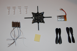
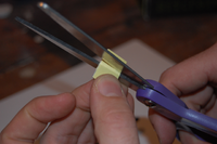
1. Check that you have everything that's needed
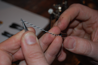
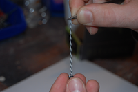
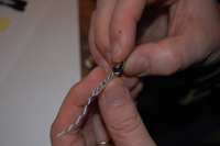
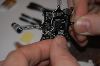
2. Twist the two motor wires together so they are easier to handle (and electromagnetic noise is reduced)
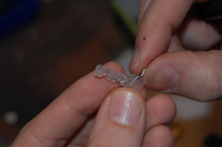
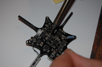
3. Thread the twisted motor wires through the motor mount arm section. It can be a bit tricky so have patience.
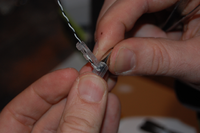
4. Insert the motor into the motor mount and be careful to not damage the motor wires while inserting it.
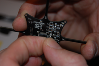
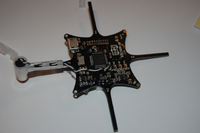
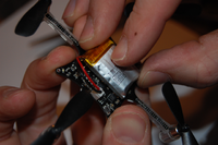
5. Press the motor mount on to the PCB arm. Be careful not to damage the wires when you do it. Start with M1.
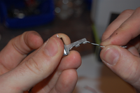
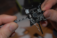
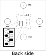
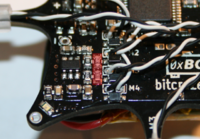
6. Try to attach the peeled end of the motor wire into the motor through hole pad. Start with white wire on round pad on M1
7. Turn the PCB around carefully not removing the wire from the hole and solder it from the top of the PCB. The square pads can take a bit longer to heat up as they are connected to the battery supply copper plane.
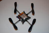
8. Repeat step 2-7 for the rest of the arms M2, M3 and M4 and remember to alternate the white and black wires according to the picture
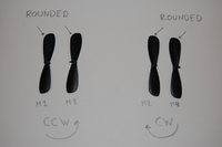
9. Attach the propellers (see drawings below for mapping). :!: You got two different packs of them with your kit, one with five clockwise and one with five counter-clockwise ones, take care to really use propellers from both packages, not just mounting two of them upside down, your drone won't fly otherwise :!:. Your clockwise propellers may be labeled with an “A”, otherwise look at the curvature of the tips to determine which is CW and which is CCW. The dull surface goes up, the shiny surface goes down. You will also see a small molded ring on the top surface. We recommend you sorting out the best propellers. See maximizing performance
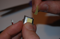
10. Attach the battery and try to centre the weight on the PCB as good as you can.
