Tiny210 Hardware Specification
Contents
- 1 OverView
- 2 Hardware Features
- 3 Hardwarew Specification
- 3.1 Power
- 3.2 Serial Port
- 3.3 USB interface
- 3.4 Network Interface
- 3.5 RS485 Interface
- 3.6 CCD AV Camera Interface
- 3.7 Audio Interface
- 3.8 TV-Out Interface
- 3.9 User Key
- 3.10 LCD interface
- 3.11 ADC Input
- 3.12 PWM Buzzer
- 3.13 Infrared Receiver
- 3.14 I2C-EEPROM
- 3.15 SD card
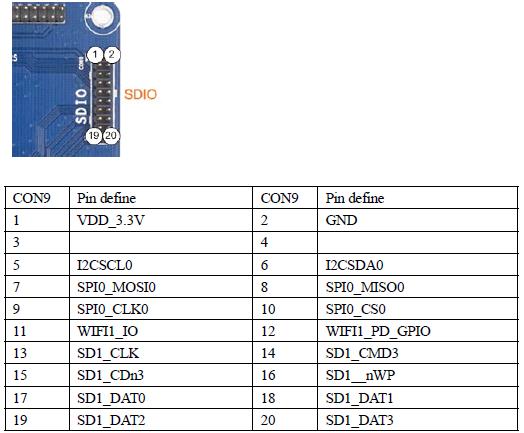
- 3.16 SDIO-II/SD-WiFi interface
- 3.17 CMOS camera interface
- 3.18 HDMI interface
OverView
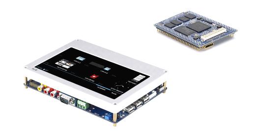
The Tiny210 Single Board Computer is a high-performance controller board introduced. It i designed based on the S5PV210 microcontroller, 512MByte DDR2 RAM, 1GByte Nand FlashRTC, Audio and net on board. It has integrated RS232, USB, Ethernet, Audio In/Out, Keyboard LCD, HDMI, TV out, camera in, SDIO WiFi Module, SD card and more other functions on board So many hardware resources provided by the expansion board, it becomes a solid reference board for customer design.We also offers a complete software development package to customers. The board supports linux2.6.35, Android2.3 operating system and is provided with complete basic drivers which enable a quick channel to evaluate the Samsung S5PV210 processor and customize application software. I would be an ideal development platform for multimedia and communication applications.
Hardware Features
The Tiny210 Single Board Computer is based on S3C6410 processor. This board is characterized as follows:
Tiny210 CPU board is a high-performance Cortex A8 core board. It uses Samsung S5PV210 as the main processor, running at up to 1GHz. Integrated PowerVR SGX540 S5PV210 internal high-performance graphics engine, support for 3D graphics run smoothly, and can be smooth to play 1080P video of the large size.
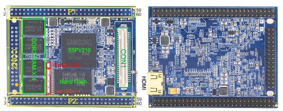
Mainly using the tiny210 double-pin 2.0mm pitch, leads to the CPU the most common functional pin, and seeks to Tiny6410 core board three rows of pin-compatible (P1, P2, and the CON2); also features the S5PV210 chips, respectively, leads to the standard miniHDMI interface, and 1.0mm pitch SMD CON1 Block (51Pin), as shown above.
Tiny210 onboard 512M DDR2 memory, and can smoothly run advanced operating system, Android, Linux and WinCE6. It is ideal for the development of high-end Internet of Things, advertising, multimedia terminal, smart home, high-end surveillance system, video game control panel device.
CPU board Hareware
- CPU 1 GHz Samsung S5PV210 with PowerVR SGX540 graphics engineCPU:
- DDR2 RAM 512MB DDR2 RAM, 32bit data bus, 200MHzRAM:
- FLASH: SLC NAND Flash: 256MB/1GB
- Multi-IO
- 2 x 60 Pin 2.0mm space DIP connector
- 1 x 51 Pin 1.0mm space SMD connector
- 1 x 30 Pin 2.0mm space DIP connector
- on Board source
- HDMI interface
- 4 x User Leds(Green)
- 1 x Power Led(Red)
- Supply Voltage from 2V to 6V
- Mechanical Dimension: 64x 50x 11mmMechanical:
- Software Android 4.0, Android 2.3, Linux 2.6.35, Qtopia-2.2.0/Qt-4.4.3/Qt-4.7Software:
Tiny210 Mother board
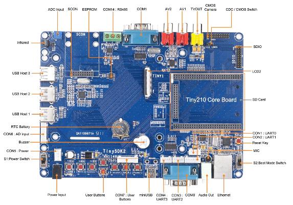
- Integrated USB 2.0 Hub: Extended 4 USB host ports, three of them as the standard side port, and one was lead by SCON interface
- AV CCD Camera In: Integrated TVP5150 video chip: 2 AV input port (RCA), can be directly connected using a CCD camera
- RS485: 1 RS485 interfaceSerial Port: 4 serial port, two of them have been converted to RS232, and leads through the DB9 Block (COM0, COM1),through the CON1, 2, 3, 4, Block leads to TTL level
- keys: 8 key
- RJ45 Ethernet port: using DM9000AEP, 10/100M adaptive
- Audio input and output: using the WM8960 professional audio chip, containing Class D amplifier on-board microphone, and supports HDMI audio and video synchronization output
- USB Slave: 1 Road, the USB 2.0 specification
- Infrared receiver: 1
- ADC input: 6 ADC input
- Buzzer: 1, control by the PWM0
- EEPROM: AT24C08 (256 Byte) for I2C test
- LCD Interface: 2 LCD interface, both 40 Pin 0.5mm Pitch Chip Block, support 3.5"-19" full color TFT display LCD
- SDIO interface: used to connect the SD WiFi module and other
- CMOS Camera interface: used to connect CMOS camera
- RTC clock: with a backup battery (according to different regions or time periods,mailing may remove the battery)
- PCB layer: 2
- PCB size: 180 x 130mm, can be easily fixed all kinds of LCD modules, especially the 7-inch LCD module
- Power supply: DC-5V
Hardwarew Specification
This section provides a definition of the pin-outs and cables to be used with all of the connectors and headers on the board.
Power
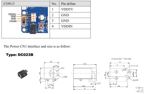
The Tiny210 is powered by an external 5V power supply. It has two power inlets: CN1 is for 5V power adapter and the white CON13 is a 4 pin socket used to connect an external power supply when the board is embedded in a closed box.
Serial Port
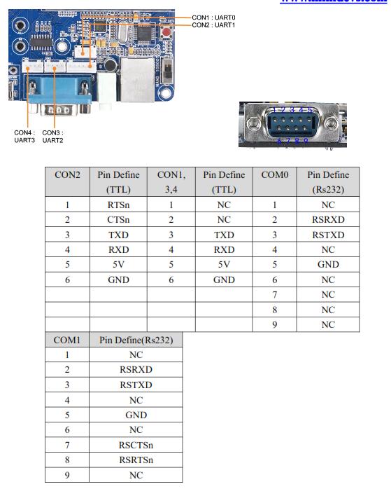
S5PV210 has 4 serial ports: UART0, 1, 2 and 3. UART0 and 1 are 5 wire serial ports and the other two are 3 wire serial ports. On this board, UART0 and UART1 is converted via RS232 to COM0 and COM1 and can communicate with a PC via a serial port cable.The rest 4 ports are connected to CPU via CON1-4. They are presented as below:
USB interface
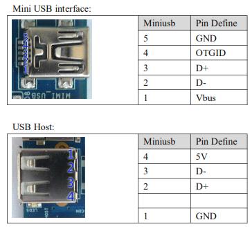
The Tiny210 board has two kindUSB interfaces. One is a USB host 2.0 which is the same as a USB interface on a PC and can connect to a USB camera, keyboard, mouse, flash drive and other USB devices, it have 3 USB Host. The other is an OTG mini USB 2.0 which is usually used to download programs to a target board. When the board runs Android it can use for ADB debug function.
Network Interface
The Tiny210 incorporates a DM9000 chip and can communicate with 10/100M networks. The RJ45 connector includes coupling filters and does not need transformers. With a common network cable, you can connect a router or switch to the Tiny210.
RS485 Interface
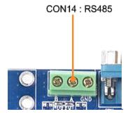
It have a RS485 interface, it is CON14.
CCD AV Camera Interface
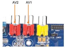
The board expand CCD AV Camera interface with TVP5150 chips, support CCD camera
Audio Interface
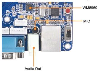
The S5PV210 supports I2S/PCM/AC97. The Tiny210 has an I2S0 interface which uses WM8960 as the CODEC chip. The audio output is a 3.5 mm spaced green plug, and WM8960 support D class power amplifier, so Tiny210 also expand the Speaker socket (CON7), the user can directly connected to 8 ohm 1W speakers. The input is an on-board microphone. To get better audio quality please move the microphone as close as possible to the audio source when recording.
TV-Out Interface
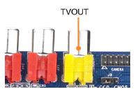
The S5PV210 has one TV output. The Tiny210 magnifies the output of DACOUT0, users can connect the board to a TV via an AV cable. Note: when connecting DACOUT0 to a TV users need to switch the TV to the CVBS mode.
User Key
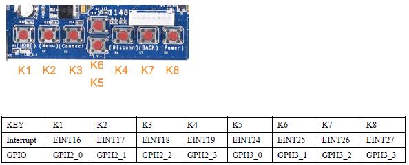
The Tiny210 has 8 test keys. They all are CPU interrupt input signals and will be triggered at a low level voltage. They can also be multiplexed to GPIO and other function interfaces. To multiplex them users can extend them through CON12. These 8 keys are defined as follows:
LCD interface
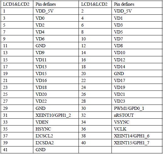
Notice: Because the use of 1-wired touchscreen, LCD1 does not include four-wire resistive touch pin from CPU, but the addition of I2C and interrupt pins (see LCD1-37,, 38,39,40), this is designed to will be able to use capacitive touch screen. LCD2 will include a more extensive CPU pins, or detail table below the schematic.
ADC Input
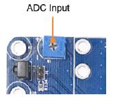
The Tiny210 has 6 A/D conversion channels, According to different purposes, scattered in various interfaces:
AIN0 is connected to the adjustable resistor W1;
AIN1, 4, 5, 6 and 7 are extended via CON6's .
The S5PV210’s AD conversion can be configured to 10-bit/12-bit.
PWM Buzzer
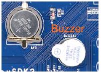
The on-board SPEAKER is controlled by PWM0, the diagram is shown below. PWM0 corresponds to GPD0_0 which can be configured as PWM output via software or used as a GPIO.
Infrared Receiver
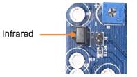
The Tiny210 has an infrared receiver. Its type is IRM3638 (or others compatible). It connects to EINT9(GPH1_1).
I2C-EEPROM
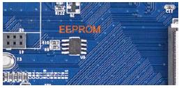
The Tiny210 has an EEPROM AT24C08 connected to CPU's I2C. It has 256 bytes memory and is mainly for testing I2C bus.
SD card
The S5pV210 has four SDIO interfaces.SDIO0 is commonly used for SD cards.
SDIO-II/SD-WiFi interface
CMOS camera interface
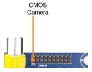
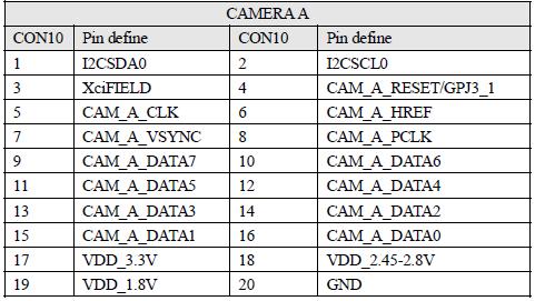
The S3C6410 has 1 CMOS camera interface. . It is a 20 pin 2.0mm connector, users can directly use the CAM130 module we provide. The CAM130 module does not have any circuits. It is basically just a converter and directly connects to a ZT130G2 camera module.
Notes: the camera interface is a multiplexed port. It can be used as GPIO by setting corresponding registers. The schematic below presents its pin details.
HDMI interface
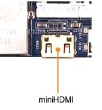
The S5PV210 support HDMI output, the Tiny210 CPU board expand the HDMI through the Type C miniHDMI interface, users can connect the board to a TV via an HDMI cable. Note: Android support LCD and HDMI output in the same time.
