MPR121 touch sensor module
Contents
Introduction
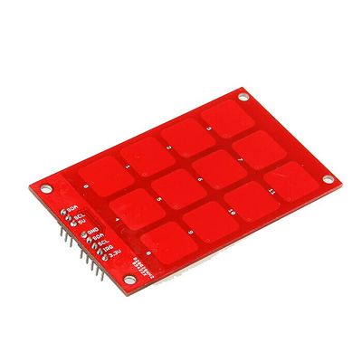
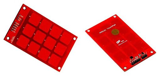
MPR121 touch sensor module is a kind of capacitive touch keyboard plate controlled by MPR121. It outputs the signal that the keys received form of IIC. The control principle and control mode are widely used in function modules of the key control in devices of household appliances (like washing machine, induction cooker etc.), MP3 player, remote control and mobile phones. MPR121 touch sensor module collects, saves and transmits data through the MPR121 IC, which increases the induction sensitivity. As the operating voltage of MPR121 is 3.3V, it can carry out IIC communication with a control board whose operating voltage is also 3.3V. In addition, a SI5902DC chip and its pilot circuit is added to the MPR121 module to make sure the MPR121 module can work under 5V, and communicate with a control IC that support 5V, thus expanding the range of application of MPR121 module.
Note: the connection method varies when it is connected to different control board that works under different voltage. You are advised to connect carefully in light of the silk-screen instruction on the PCB. The 3.3v power supply should be connected to MPR121 module when it communicates with a 5v control board. (for more detailed information, please refer to chapter Ⅳ)
Overview and Hardware Resources
Control IC: MPR121 Interface resources: 2 IIC connectors Two power input ports: 3.3v and 5v Weight: 13g Size: 80mm*48mm*10mm
Software
Test code program: Media:MPR121 Touchpad.rar
data Source
Interface
Interface Layout
Interface specifications
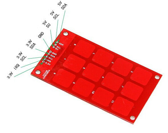
The interface layout of MPR121 touch sensor module is displayed above. 3.3v and 5v: for power supply
Common IRQ: when MPR121 communicates with a 3.3v or 5v CPU, it will send signals to the master control. The IRQ provides input when connected with a periphery controller.
3.3v CLK/ DATA pins: for IIC communication when connected to a 5v CPU.
CND: for ground
Development Environment Setting
Interface Connecting and Setting
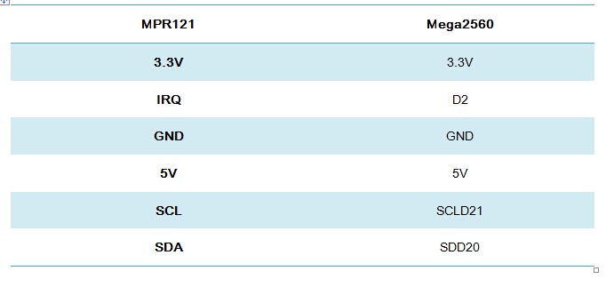
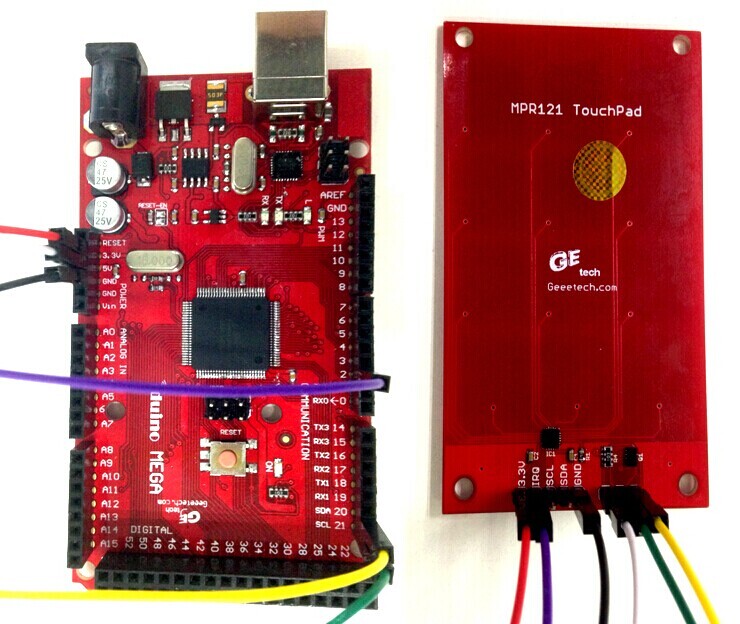
MPR121 touch sensor module can be connected and communicate with PCB whose operating voltage can be both 3.3v and 5v. As mentioned above, the connection method varies when connecting to different PCBs with different operating voltage. Here we set it as an example to connect it with Mega 2560.
Get Started
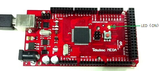
1)Connect MPR121 to Mega2560 with a USB cable, if the LED lights, the connection is ok, as in the following picture.
2)Connect MPR121 touch sensor module with Mega 2560 in light of 3-1
3)Open the test code file mpr121.ino with Arduino1.0.1, you are now in the interface as below:
4)Select the type of board: Tools—Board—Arduino Mega 2560 or Mega ADK.
5)Choose the serial port under use: Tools—Serial Port—COM.
6)Click File:Button1 to upload program. When Arduino1.0.1 shows an interface as below, the uploading completed.
