Sanguinololu
Contents
Introduction
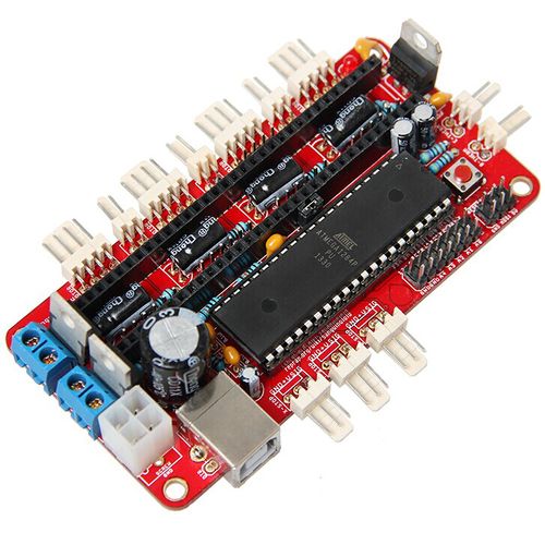
Sanguinololu is highly integrated with all the functions that a 3D printer needs. It is of high capacity-price ratio and support Reprap style printer and other CNC devices (Computer numerical control devices). The 4 stepper drivers are completely compatible with A4988 and DRV8825. Sanguinololu adapts developer friendly expansion port supporting I2C,SPI,UART,as well as ADC pins. All 14 expansion pins are reserved to be GPIO as well. Power supply for sanguinololu is also flexible; users can choose ATX-4 power input or the 2pin connector to supply.
Features:
1.support multiple communication configurations :
UART1(RX TX)、I2C(SDA SCL)、SPI(MOSI MISO SCK)、PWM PIN(one)、ADC(five)
2.Support multiple power configurations:
Main board supplied by 5mm screw terminal, and optional 4pin ATX connector: 7v-12v
3.Adapts Atmel's ATmega644P - ATmega1284 drop-in compatible. Currently, we use 1284P, the bootloader has been burned before shipping, and users can put it into use after burning the programming code.
4.Adapts FT232RL on-board for USB connectivity, which is an industrial USB-serial chip, ensuring the stability and convenience of installation.
5.Selectable power supply for end stops (5v or12v).
6.With 4 stepper driver on board (Z supports 2 stepper motors)
7.2 N-MOSFETs for extruder/bed, or other peripheral device
8.Supports LCD 2004 module, available for off-line printing.
Version 1.3a - Updated July 21, 2011
Version 1.3a has no software changes - the pin assignments remain the same and your 1.2+ compatible firmware should work here fine. The hardware changes:
- Removed the Molex HDD connector in favor of using the voltage regulator - some power supplies give a dirty 5V signal when there is no motherboard load, so its better to just use the power supply's ATX+4 connector and the 5V voltage regulator.
- Added a jumper to enable/disable USB auto-reset. This way if you're printing from an SD card using SDSL you can disconnect your USB and reconnect it without interrupting a print.
- R7 and R8 are now 100k pull-up resistors that are on the stepper-enable lines. This ensures the stepper motors stay disabled and don't move while uploading new firmware, rebooting, etc. The current limiting resistors for the FTDI are gone.
- There is an extra Z-motor header for Prusa Mendel.
Overview and Hardware Resources
size:100mm x 60mm
weight:73g
Software Resources
Compiling environment: Arduino IDE http://www.geeetech.com/wiki/images/3/36/Arduino-1.0.5-r2-windows.zip
Firmware: Marlin http://www.geeetech.com/wiki/images/3/39/Marlin-Marlin_v1.zip
Pc software:
printrun http://www.geeetech.com/wiki/images/e/e1/Printrun-Win-Slic3r-10Mar2014.zip
Repetier-Host http://www.geeetech.com/wiki/images/3/36/SetupRepetierHost_1_00.zip
Sanguinololu drive: http://www.geeetech.com/wiki/index.php/Sanguinololu
Bugs
- The USB 5V VBUS is connected to the output of the 5V regulator. This is bad for the regulator and bad for the PC. Some users report the regulator getting very hot (because it is trying to power the PC), other users report the PC giving USB over current errors. Nophead and Nothinman recommend cutting the 5V track to the USB connector. The only downside is the board needs the 12V supply before it will do anything, but who cares?
An alternate fix for the 1.3a board is to cut the trace between the USB chip pin 4 and C13. This is functionally identical to building a Sanguinololu without the USB port and FT232RL and using an offboard USB-serial cable. The advantage over cutting the 5V trace at the USB connector is that the USB serial port doesn't disappear from the host PC when the printer is switched off, which can anger host software that is still running.
- When the bootstrap loader runs during reset and when downloading firmware the motors are enabled due to pull-downs on the Pololus (The enable pins are pulled up by 100K resistors on the Sanguinololu but they are pulled down by 100K on each Pololu). The step pins are floating and this can cause random motor movements. The E step pin is next to E dir pin which the bootstrap thinks is an LED to be flashed. Crosstalk can cause the extruder to spin when firmware is being loaded. This is not good as it will be cold, so could damage the hot end. Nophead recommends changing the enable line pull ups (R7 and R8) to 4K7 to ensure the motors are disabled until the firmware enables them.
A software fix is to use the the Gen7 boot strap that does not flash the non-existent LED.
- The pads and traces on the board are not robust enough to handle the high current involved when controlling the heated bed with the sanguinololu's dedicated mosfet. If left as is, the board will heat up in this area, could be damaged and the plastic connectors discolored. To fix, simply add a direct current path by way of (preferably insulated) wire from the 12v input to the 12v pins on the Heated Bed (HB) connector; from the center pin of the HB mosfet to the two ground pins on the HB connector; and from the ground pin on the mosfet to the ground input of the board (probably the ground side of the 12v connector). Find the appropriate traces using continuity check or resistance mode on your multimeter, and check after to ensure you didn't create a short between any of these components in the process. It would be prudent to check for shorts before starting so you don't waste effort trying to fix a short you think you just created but was already there before you applied this fix. To understand this fix, pretend that no traces exist between the high current pathways of the 12v input and 12v pins of the HB connector; the ground input and the ground pin on the mosfet, and the center pin of the mosfet and ground pins on the HB connector. Assume you must create these pathways, then do so!
file
firmware download
Setup your Sanguinololu to communicate with your PC over USB
1) Download the Virtual Com Port USB drivers from http://www.ftdichip.com/Drivers/VCP.htm, and unzip
2) Connect to your Sanguinololu to a power supply (PC ATX supply etc) and connect the usb
3) At hardware detection, point to your driver folder from above. This will install a new com port (COM7 in my case)
4) Download pronterface, a nice gui to control your hardware, from http://koti.kapsi.fi/~kliment/printrun/, and unzip
5) Open pronterface, change to the COM port to the new one created above and set the rate to 250000. Hit Connect to connect/test.
Download fresh Marlin firmware and the Arduino IDE to edit and compile your firmware
1) Get the Marlin Firmware from File:Sanguinolu.zip, extract to a new marlin/folder
2) Download the Arduino IDE from http://arduino.cc/en/Main/Software, extract to a new Arduino/ folder
3) Download the Sanguino-specific Arduino IDE files from http://code.google.com/p/sanguino/, extract to hardware/ in the Arduino/ folder from above
4) Open the Arduino IDE, select Board -> Sanguino W/Atmega128P *, then select tools -> serial port -> COM[7] (from above)
5) From the Arduino IDE, select File -> Open -> [Your Marlin directory] -> Marlin.pde to open the firmware for editing
6) Make sure the following is set in the Configuration.h file '#define MOTHERBOARD 62' to tell the firmware what hardware you are running on
7) Make any other changes to the Configuration.h file you need here
8) Compile your code using Verify -> Verify / Compile
9) Select File -> Upload to transfer to your hardware **
How to buy
http://www.geeetech.com/reprap-sanguinololu-rev-13a-assembled-p-609.html


