L298N Motor Driver Board
Introduction
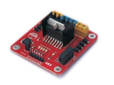
Double H driver module uses ST L298N dual full-bridge driver, an integrated monolithic circuit in a 15- lead Multiwatt and PowerSO20 packages. It is a high voltage, high current dual full-bridge driver designed to accept standard TTL logic levels and drive inductive loads such as relays, solenoids, DC and stepping motors. Two enable inputs are provided to enable or disable the device independently of the input signals. The emitters of the lower transistors of each bridge are connected together and the corresponding external terminal can be used for the con-nection of an external sensing resistor. An additional supply input is provided so that the logic works at a lower voltage.
Specification
- Driver: L298N
- Driver power supply: +5V~+46V
- Driver Io: 2A
- Logic power output Vss: +5~+7V (internal supply +5V)
- Logic current: 0~36mA
- Controlling level: Low -0.3V~1.5V, high: 2.3V~Vss
- Enable signal level: Low -0.3V~1.5V, high: 2.3V~Vss
- Max power: 25W (Temperature 75 cesus)
- Working temperature: -25C~+130C
- Dimension: 60mm*54mm
- Driver weight: ~48g
- Other extensions: current probe, controlling direction indicator, pull-up resistoer switch, logic part power supply.
Hardware Diagram
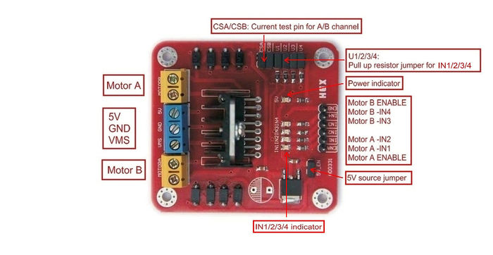
- CSA: The current test pin for motor A, this pin can be wired a resistor for current testing or tied a jumper to disable it.
- CSB: The current test pin for motor B, this pin can be wired a resistor for current testing or tied a jumper to disable it.
- VMS: VMS is the 5V-35V power source for motor. VMS is positive, GND is negtive.
- 5V: Power input for the logic circuit on the board.
- 5V-EN: 5V source jumper. When the jumper is put on, The 78M05 supplies the 5V power for logic circuit on the board from the VMS port(7V < VMS < 18V). The power of logic circuit of the board is supplied by the 5V port when this jumper put off.
- U1/2/3/4: Pull up resistor for IN1/2/3/4. Putting on the jumper enable the pull up resistor for the microcontroller, putting off it disable it.
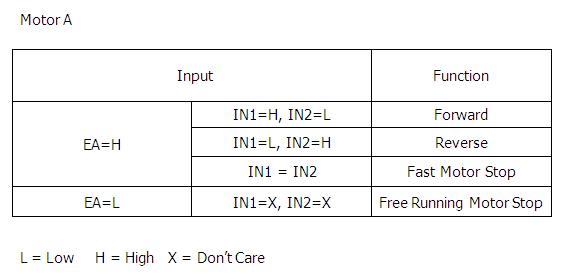
- EA/EB: EA/EB is the enable pin for the two motor A/B, the motor speed also can be controlled by the PWM of this pin.
- IN1/2/3/4: IN1/2/3/4 is the pin for the motor control. Motor B is same as Motor A.
Example
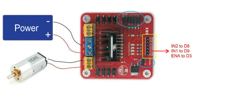
int IN1=8;
int IN2=9;
int ENA=3;
void setup()
{
 pinMode(IN1,OUTPUT);
 pinMode(IN2,OUTPUT);
}
void loop()
{
 analogWrite(ENA, 200);// motor speed
 digitalWrite(IN1,LOW);// rotate forward
 digitalWrite(IN2,HIGH);
 delay(2000);
 digitalWrite(IN1,HIGH);// rotate reverse
 digitalWrite(IN2,LOW);
 delay(2000);
}
Document
How to buy
Click here to buy [L298N Motor Driver Board http://www.geeetech.com/l298n-stepper-motor-driver-board-p-567.html]


