Tiny6410 Hardware Specification
Contents
- 1 Tiny6410 core board interface instruction
- 2 Tiny6410 CPU board
- 3 Mother board
- 4 Interface
- 4.1 Power In
- 4.2 Serial port
- 4.3 USB interface
- 4.4 SCON interface
- 4.5 Network interface
- 4.6 Audio interface
- 4.7 TV-out interface
- 4.8 JTAG
- 4.9 LED
- 4.10 Key
- 4.11 LCD interface
- 4.12 ADC input
- 4.13 PWM(buzzer)
- 4.14 temperature sensor
- 4.15 IR
- 4.16 I2C-EEPROM
- 4.17 SD card slot
- 4.18 SDIO-II/SD-WiFi interface
Tiny6410 core board interface instruction
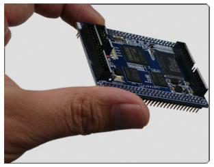
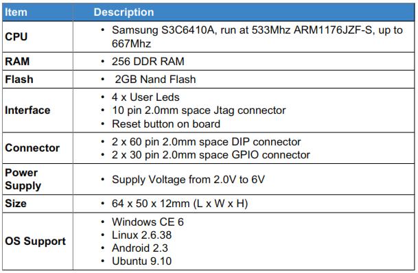
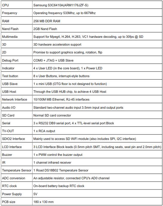
Tiny 6410 is a embedded development board based on ARM11 (SUMSUNG S3C6410). The S3C6410 is designed based on ARM1176JZF-S core integrates powerful multi-media processing unit, supports Mpeg4, H.264/H.263, etc video hardware decoding and encoding and outputs to LCD an TV.It includes 3D graphical hardware accelerator for OpenGL ES1.1&2.0 accelorated rendering, in addition, it also supports 2D graphic smooth zooming and inverting.
Tiny6410 is designed with high-density 6-layer PCB which integrates 128M/256M RAM, SLC NAND Flash(256M/1GB) or MLC NAND FlASH(2GB) memory. The dimension is 64 x 50mm, powered by 5 supply. The board also integrates the CPU voltage convertor and professional reset chip. The 2.0mm pitch headers draw out the common intefaces for the secondary development of the developers who doesn't want to design the CPU board.
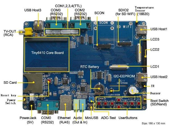
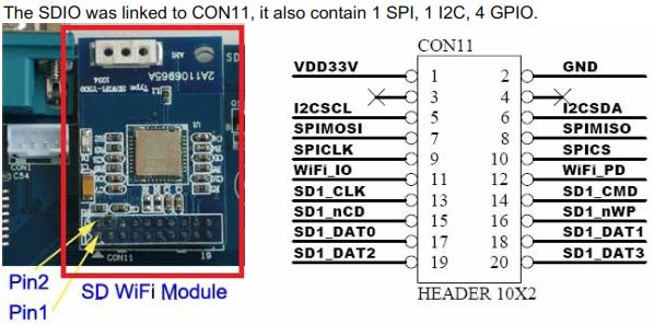
Tiny6410SDK is a mother board refer to the Tiny6410 core-board, it helps the developers for the function verification and extensive development. This mother board includes 3 LCD interfaces and 4-wire touch screen interface, 100M standard Ethernet interface, standard DB9 interface, MiniUSB2.0 interface, USB Host1.1, 3.5mm audio output, standard TV-OUT interface, SD card interface, IR receiver and etc. Also it draw out 4 channel TTL serial port, 1 channel TV-OUT, SDIO2 interface(connect to SD Wifi).It also have buzzer, I2C-EEPROM, spare battery, AD variable resistor, 8 interrupt buttons.
We consider to fix the common LCD module on the mother board such as 3.5", 4.3 TFT, 7"TFT LCD and etc for user's convenience so that they won't mess wires up the wires.
We also make use of the feature of SD card booting of 6410. Just copying the object files to the SD card(up to 32G), without connecting to the computer, you can install any embedded system(windowsCE6/Linux/Android/Ununtu/uCOS/2) easily in our development board or run the system with SD card.
Tiny6410 CPU board
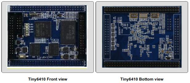
Feature of the Tiny6410 CPU board
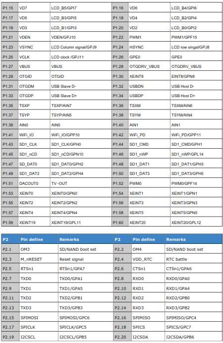
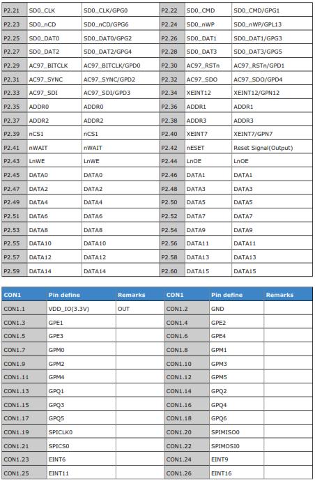
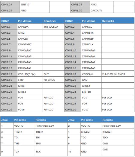
Pin definition of the Tiny6410 CPU board
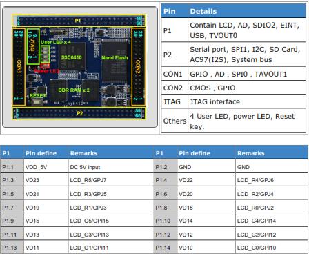
Tiny6410 CPU board use the 2.0mm pitch double pin, leads to a total of 4 groups:
P1, P2, CON1, CON2.
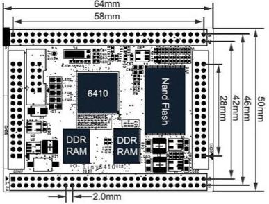
P1 and P2 are each 60 Pin; CON1 and CON2 are each 30Pin, leads to a total of 180 Pin.The follow shown is the layout description:
Dimensions of the Tiny6410 CPU board
Mother board
Feature of the Tiny6410 SDK board
Interface
Power In
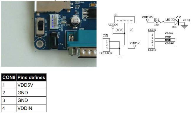
The board use 5V power supply, it have two method to power the board. One is the D-jack (CN1)power in,the others is 4Pin header(CON8).
Serial port
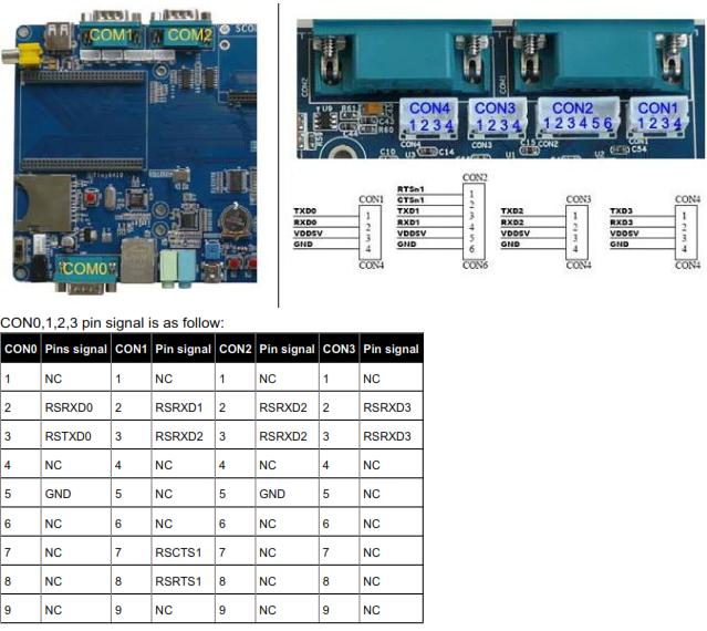
S3C6410 have four serial port, it is UART0,1,2,3, UART1 is 5-wired serial, the others is 3-wired serial.In Tiny6410SDK board, COM0,1,2 was linked to DB9 interface in RS232, you can link it to PC.And the all serial was linked from the board to CON1, CON2, CON3, CON4 in TTL.
USB interface
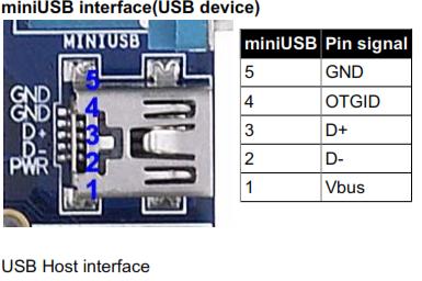
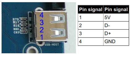
In Tiny6410 board, it have 5 usb interface, there are 4 usb host, and the other is usb slave interface
SCON interface
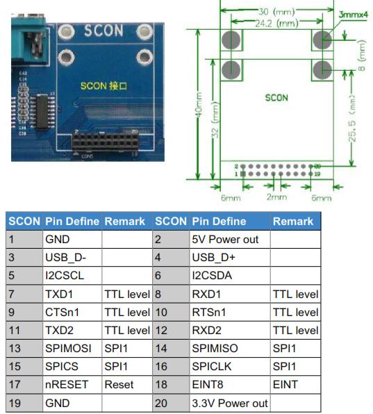
In order to use more serial port peripherals, we deliberately designed the SCON interface and call it"serial port Center, "which includes two serial ports, an I2C interface, an SPI interface, a USB Host port, but also Have a GPIO port, etc., and includes 5V and 3.3V power supply output pin, as shown in Figure (right side interface mechanical dimensions SCON):
Network interface
the board carries a 100M network card interface, use the DM9000 chips.
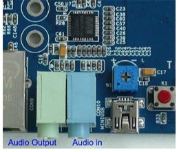
Audio interface
TV-out interface
The board provide 1 TV-out interface, it is from DACOUT0. When you use DACOUT0, you should set the TV mode for CVBS mode.
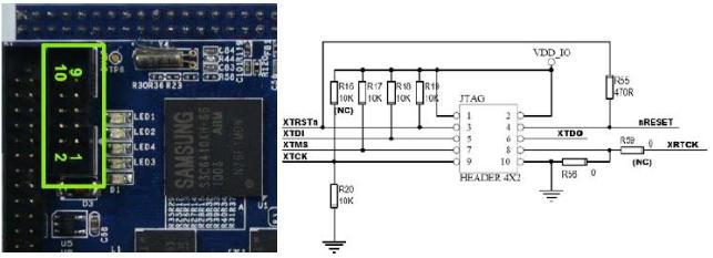
JTAG
LED
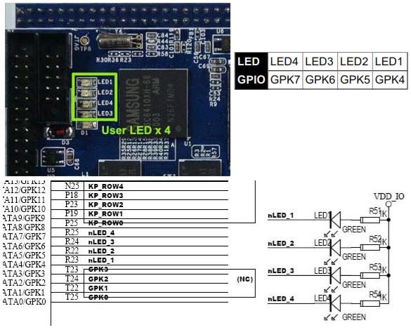
The board have 4 LED, you can control it, When output GPIO for 0, the LED will be light.
Key
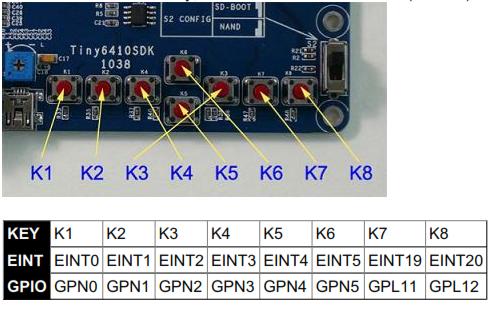
The board have 8 user key, and it can be linked for GPIO(CON12).
LCD interface
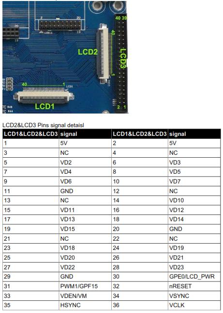
The board have 3 LCD interface, it have the same signal, LCD1 and LCD2 is the 40pin 0.5mm pitch interface, LCD3 is the 40pin 2.0mm interface.
ADC input
The board have 2 Chanel A/D, AIN0 was linked to W1, it can be configure 10/12 bit.
PWM(buzzer)
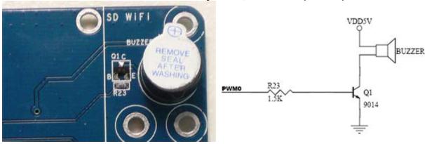
The Buzzer in the board was controlled by PWM, it is PWM0(GPF14)
temperature sensor
IR
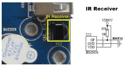
In the board, it have IR, the name is IRM3638, It link to the pin EINT12 as received pins.
I2C-EEPROM
The I2C was linked to EEPROM, AT24C08, it was 256byte. only for test the I2C.
SD card slot
It have a SD card slot, can support 32GByte
