Difference between revisions of "Arduino GPRS Shield"
(→Power Up the GPRS Shield) |
|||
| Line 63: | Line 63: | ||
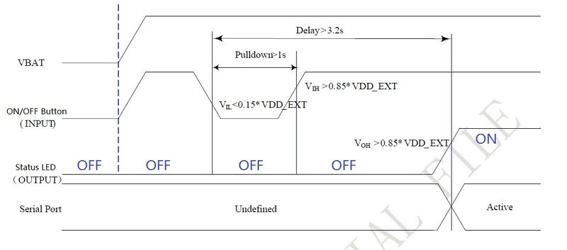
1, Hardware Triger; Press the ON/OFF Button about two seconds.The power up scenarios illustrates as following figure: | 1, Hardware Triger; Press the ON/OFF Button about two seconds.The power up scenarios illustrates as following figure: | ||
| + | [[File:GPRS ONs.jpg|800px]] | ||
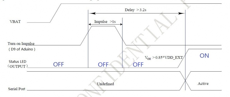
| − | [[File:GPRS | + | 2, Software Triger; If use this way to power up the GPRS Shield, JP need to be soldered, then Digital Pin 9 of the Arduino will act as Software Triger port and Digital Pin 9 can not be use as other purpose. Then give Digital Pin 9 a Turn on Impulse can power up the GPRS Shield. The power up scenarios illustrates as following figure: |
| + | [[File:GPRS Pwrs.jpg|800px]] | ||
| − | + | The following code is power up subroutine for Arduino if using software triger: | |
| + | |||
| + | void powerUp() | ||
| + | { | ||
| + | pinMode(9, OUTPUT); | ||
| + | digitalWrite(9,LOW); | ||
| + | delay(1000); | ||
| + | digitalWrite(9,HIGH); | ||
| + | delay(2000); | ||
| + | digitalWrite(9,LOW); | ||
| + | delay(3000); | ||
| + | } | ||
==== Power Down the GPRS Shield ==== | ==== Power Down the GPRS Shield ==== | ||
Revision as of 01:53, 12 March 2012
Contents
Introduction
The GPRS Shield is based on SIM900 module from SIMCOM and compatible with Arduino and its clones. The GPRS Shield provides you a way to communicate using the GSM cell phone network. The shield allows you to achieve SMS, MMS, GPRS and Audio via UART by sending AT commands (GSM 07.07 ,07.05 and SIMCOM enhanced AT Commands). The shield also has the 12 GPIOs, 2 PWMs and an ADC of the SIM900 module(They are all 2V8 logic) present onboard.
Features
- Quad-Band 850 / 900/ 1800 / 1900 MHz - would work on GSM networks in all countries across the world.
- GPRS multi-slot class 10/8
- GPRS mobile station class B
- Compliant to GSM phase 2/2+
- Class 4 (2 W @ 850 / 900 MHz)
- Class 1 (1 W @ 1800 / 1900MHz)
- Control via AT commands - Standard Commands: GSM 07.07 & 07.05 | Enhanced Commands: SIMCOM AT Commands.
- Short Message Service - so that you can send small amounts of data over the network (ASCII or raw hexadecimal).
- Embedded TCP/UDP stack - allows you to upload data to a web server.
- RTC supported.
- Selectable serial port.
- Speaker and Headphone jacks
- Low power consumption - 1.5mA(sleep mode)
- Industrial Temperature Range - -40°C to +85 °C
Specifications
Application Ideas
- M2M (Machine 2 Machine) Applicatoions.
- Remote control of appliances.
- Remote Weather station or a Wireless Sensor Network.
- Vehicle Tracking System with a GPS module.
Cautions
- Make sure your SIM card is unlocked.
- The product is provided as is without an insulating enclosure. Please observe ESD precautions specially in dry (low humidity) weather.
- The factory default setting for the GPRS Shield UART is 19200 bps 8-N-1. (Can be changed using AT commands).
- NewSoftLibrary library only support baudrate under 38400bps, it may lose data while communicate over 38400bps.
- The standard NewSoftSerial library doesn't have support for receive on the Mega. Bhagman has written a new version of NewSoftSerial that has this support:
http://www.arduino.cc/cgi-bin/yabb2/YaBB.pl?num=1287382108
http://code.google.com/p/rogue-code/downloads/detail?name=NewSoftSerial10c-withMegaAndStream.zip
He've tried this new library. One limitation is that it only works on pins that support interrupts(Pin11,12), so on the Mega it only works on Hardware UART.
- The default Buffer of Rx in NewSoftSerial.h is 32, you may experience some data lose while the returns of SIM900 are many(Receiving SMS/TCPIP), you can try to change the Buffer of Rx in NewSoftSerial.h into
Hardware Diagram
Getting Started
AT Command syntax
AT Command is simple textual commands communicated with GPRS Shield over its serial interface (UART). The "AT" or "at" prefix must be set at the beginning of each Command line. To terminate a Command line enter <CR>. Commands are usually followed by a response that includes. "<CR><LF><response><CR><LF>" Throughout this document, only the responses are presented, <CR><LF> are omitted intentionally.
Note: A HEX string such as "00 49 49 49 49 FF FF FF FF" will be sent out through serial port at the baud rate of 115200 immediately after SIM900 is powered on. The string shall be ignored since it is used for synchronization with PC tool. Only enter AT Command through serial port after SIM900 is powered on and Unsolicited Result Code "RDY" is received from serial port. If auto-bauding is enabled, the Unsolicited Result Codes "RDY" and so on are not indicated when you start up the shield, and the "AT" prefix, not "at" prefix must be set at the beginning of each command line.
For more information please refer to AT Commands Manual v1.03.
Power Up and Power Dowm the GPRS Shield
Power Up the GPRS Shield
The GPRS Shield can be turned on by two ways:
1, Hardware Triger; Press the ON/OFF Button about two seconds.The power up scenarios illustrates as following figure:

2, Software Triger; If use this way to power up the GPRS Shield, JP need to be soldered, then Digital Pin 9 of the Arduino will act as Software Triger port and Digital Pin 9 can not be use as other purpose. Then give Digital Pin 9 a Turn on Impulse can power up the GPRS Shield. The power up scenarios illustrates as following figure:

The following code is power up subroutine for Arduino if using software triger:
void powerUp()
{
 pinMode(9, OUTPUT);
 digitalWrite(9,LOW);
 delay(1000);
 digitalWrite(9,HIGH);
 delay(2000);
 digitalWrite(9,LOW);
 delay(3000);
}