Difference between revisions of "Rumba"
(→Introduction) |
|||
| Line 52: | Line 52: | ||
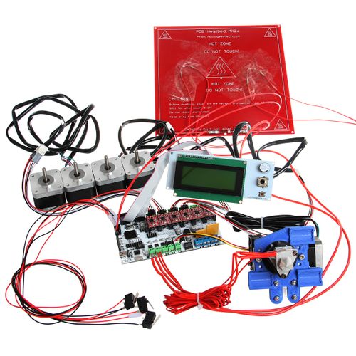
[[File:Rumba5.jpg|4oopx|]] | [[File:Rumba5.jpg|4oopx|]] | ||
| + | |||
| + | ===Interface Resources Instruction=== | ||
| + | 1. Five interface for temperature measurement: three for extruders, one for hot bed and one for environment. | ||
| + | |||
| + | 2. Five PWM: three for the heating of extruder and hot bed, one for Fan rotation and one for lighting. | ||
| + | |||
| + | 3. Six end stops: Xmin/Xmax/Ymin/Ymax/Zmin/Zmax, which can connect ends tops of machinery and optics or the Hall Sensor. | ||
| + | |||
| + | 4. Supporting JTAG makes it possible to conduct software development. | ||
| + | |||
| + | |||
| + | ===Jumper Instruction === | ||
| + | |||
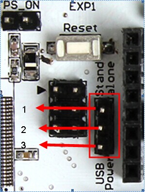
| + | [[File:RUMBA6.jpg]] | ||
| + | |||
| + | 1. MCU power options: connect the jumper cap of 1 and 2 to provide external power. Connect the jumper cap of 2 and 3 to provide USB power. | ||
| + | |||
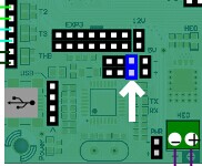
| + | [[File:RUMBA 7.jpg]] | ||
| + | |||
| + | |||
| + | 2. Pulling out Jumper cap to make MCU into Mode DFU | ||
| + | |||
| + | ==Setting up Operational Environment== | ||
| + | ===Interface Connecting and Setting=== | ||
| + | |||
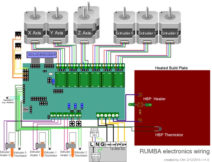
| + | [[File:Rumba 8.jpg|500px|]] | ||
Revision as of 08:13, 16 July 2014
Contents
Introduction
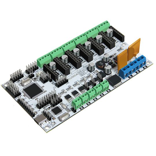
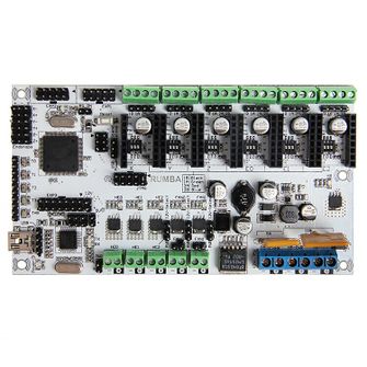
As the core of 3D printer, Rumba’s running is controlled by electric part. Rumba uses the integrated control board on the base of ATmega’s AVR processor. The circuit board is developed for 3D printer, carver, laser cutter and other CNC. Controlling the 3Dprinter with USB or printing through SD memory card. With integrated design, it is easy to install and debug. Using Arduino IDE as the development software, the firmware update and parameter configuration are both easy to use. Compared with other 3D Printer control board, Rumba has one more motor driver and less plug-in part so that it can improve the connectivity and stability. Detailed parameters are as follows.
1 Use the same CPU as that of Arduino MEGA as main control chip, Atmega2560 cooperates with high-performance USB chip in order that it is compatible with all RAMPS relevant firmware;
2 Five interfaces as input for temperature sensor.
3 All pins being drawn out to permit more function expansion.
4 With expanding interface, it can connect the LCD displayed and the development board.
5 Servo’s expanding interface to make the automatic leveling easier to add
6 Supporting 6 pieces of 16 micro stepping drivers of A4988.
7 PWM DC output( heating pipe ,fan), six channels of output( 1 channel of high current, 3 channels of medium current and 2 channels of low current). Use low on-resistance MOS Varactor as driver and LED tests each output.
8 Power-supply: power input 12v-35v, dual power to avoid interaction; hot bed connects 11A, 12V, other sections connect 5A, 12V and add a 12V cooler to reduce the high temperature from the high current of Mega controller.
9 Adopt the popular control board firmware-Marlin, which has good stability, usability and function.
Appearance and Hardware Resources
Size: 135*175mm Weight: 90g
Software Resources
Compiling environment: Arduino IDE
Firmware: Marlin
HostComputer Software:printrun Repetier-Host (supporting Chinese)
References
Arduino IDE:http://arduino.cc/en/Main/Software
Marlin:https://github.com/ErikZalm/Marlin/tree/Marlin_v1
Printrun:http://koti.kapsi.fi/~kliment/printrun
Repetier-Host:http://www.repetier.com/download/
Interface Resources
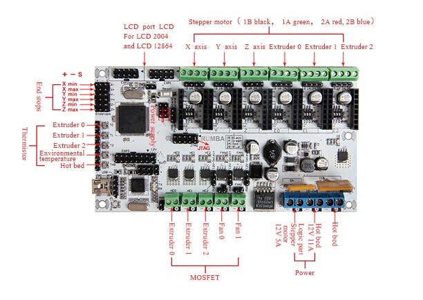
Interface Layout
Interface Resources Instruction
1. Five interface for temperature measurement: three for extruders, one for hot bed and one for environment.
2. Five PWM: three for the heating of extruder and hot bed, one for Fan rotation and one for lighting.
3. Six end stops: Xmin/Xmax/Ymin/Ymax/Zmin/Zmax, which can connect ends tops of machinery and optics or the Hall Sensor.
4. Supporting JTAG makes it possible to conduct software development.
Jumper Instruction
1. MCU power options: connect the jumper cap of 1 and 2 to provide external power. Connect the jumper cap of 2 and 3 to provide USB power.
2. Pulling out Jumper cap to make MCU into Mode DFU
