Difference between revisions of "Mini Light Sensor"
(→Wiring diagram) |
(→Wiring diagram) |
||
| Line 22: | Line 22: | ||
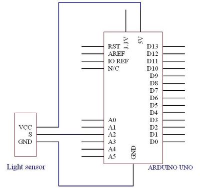
==Wiring diagram== | ==Wiring diagram== | ||
| − | [[File:Light | + | [[File:Light sensor2.jpg|400px]] |
== Example code == | == Example code == | ||
Revision as of 02:19, 26 June 2012
Contents
Introduction
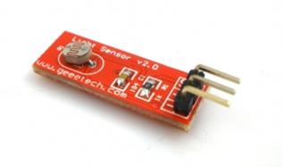
The Light Sensor brick Module is based on photoresistor, It measures the environment light intensity and input data to Arduino through the analog IO port of Sensor Shield. Great tool for light following robot, gardening system or home alert system.
Building interactive work is as easy as piling bricks, just plug it to Arduino Sensor Shield with a buckled cable, and make it looks professional and neat
Technical Specifications:
A photoresistor or light dependent resistor is a resistor whose resistance decreases with increasing incident light intensity; in other words, it exhibits photoconductivity. It can also be referred to as a photoconductor or CdS device, from "cadmium sulfide," which is the material from which the device is made and that actually exhibits the variation in resistance with light level. Note that although CdS is a semiconductor, it is not doped silicon.
A photoresistor is made of a high resistance semiconductor. If light falling on the device is of high enough frequency, photons absorbed by the semiconductor give bound electrons enough energy to jump into the conduction band. The resulting free electron (and its hole partner) conduct electricity, thereby lowering resistance.
Typical Application
- camera light meters
- street lights
- clock radios
- alarm devices
- outdoor clocks
- solar street lamps
- solar road studs
Wiring diagram
Example code
int sensorPin = 5;
int value = 0;
void setup() {
 Serial.begin(9600);
}
void loop() {
 value = analogRead(sensorPin);
 Serial.println(value, DEC);
 delay(50);
}
How to buy
Click here to buy Light Sensor

