Difference between revisions of "Geeetech GTM32 Board"
(→Firmware) |
(→How to Install firmware) |
||
| Line 185: | Line 185: | ||
1. Download “toolkit-os” and upzip the file. Here is the link | 1. Download “toolkit-os” and upzip the file. Here is the link | ||
| − | [https:// | + | [https://github.com/Geeetech3D/Smartto/tree/master/eclipse Firmware-download-tool] |
[[File:Image001.png]] | [[File:Image001.png]] | ||
Revision as of 09:03, 24 May 2018
Contents
Introduction
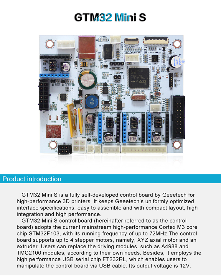
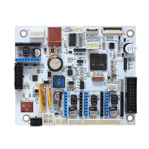
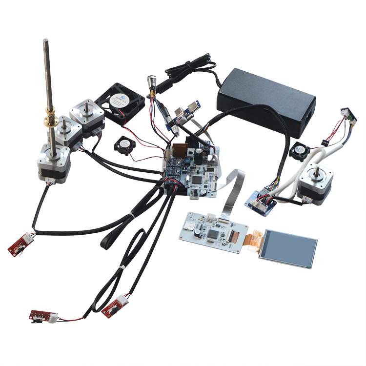
GTM32 is a fully self-developed control board by Geeetech for high-performance 3D printers. It keeps Geeetech’s uniformly optimized interface specifications, easy to assemble and with compact layout, high integration and high performance.
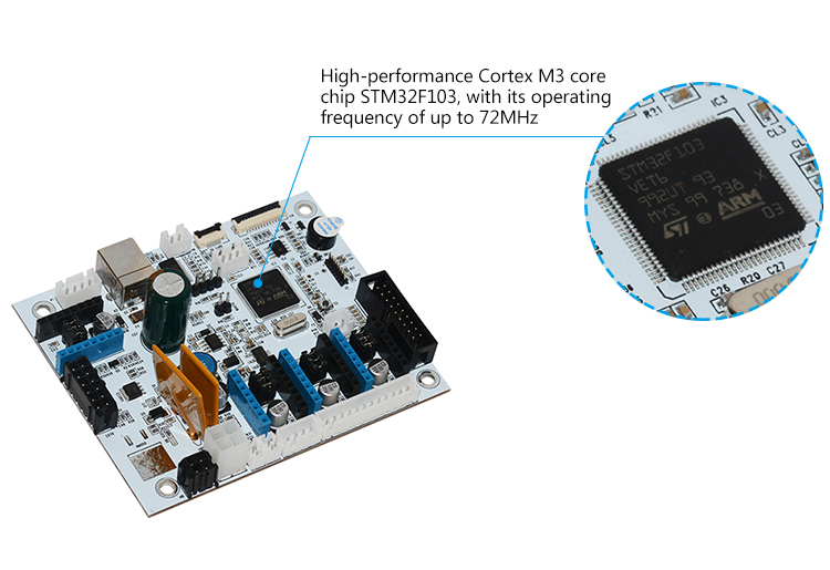
GTM32 control board (hereinafter referred to as the control board) adopts the current mainstream high-performance Cortex M3 core chip STM32F103, with its running frequency of up to 72MHz.The control board supports up to 4 stepper motors, namely, XYZ axial motor and an extruder. Users can replace the driving modules, such as A4988 and TMC2100 modules, according to their own needs. Besides, it employs the high performance USB serial chip FT232RL, which enables users to manipulate the control board via USB cable. Its output voltage is 12V.
Features
a. Adopting high-performance Cortex M3 core chip STM32F103, with its running frequency of up to 72MHz.
b. Using high-performance USN serial chip FT232RL, manufactured by FTDI, compatible with Windows, OS X, Linux etc. mainstream operation system.
c. The output voltage of GTM32 control board is 12V. It is characterized by dual power supply design, powering up the hotbed and other electronic components respectively. The current for hotbed is 9A and 7A for other parts.
d. The main circuit adopts in-line fuse, with overcurrent protection and reverse protection. The USB power supply interface has a restorable fuse, with its current at 500mA.
e. The control board features three interfaces for PWM fans.
f. Supporting up to 4 stepper motors, namely, XYZ axial motor and an extruder. The common stepper motor drivers are A4988 and TMC2100.
g. Dual temp sensor input: one for the extruder, the other for the hotbed. 100K thermistor is recommended.
h. The control board comes with expansion interfaces for LCD display and SD card, supporting stand-alone printing.
i. With a buzzer on board.
Hardware Resources
Here is a list of the hardware for GTM32 control board.
1. Power supply unit: 12V output voltage
2. Hotbed interface and extruder interface
3. 4 stepper motor drivers (3 for X, Y, Z axis motors and 1 for the extruder)
4. Interfaces for LCD display & SD card.
5. 6 endstop interfaces
6. 3 interfaces for thermistor
7. 3 interfaces for PWM fan
8. 3D Touch interface
9. Serial interface for Wi-Fi module
Diamension: 102mm*84mm* 27.5mm
Weight: 79.00 g
Interface specifications:
Extruder interface: MX (3.0mm-2*6Pin)
Hotbed interface: MX (3.0mm-2*2Pin)
X, Y, Z motor interfaces: XH (2.54mm-12Pin)
Control board Fan interface: PH (2.00mm-2Pin)
Endstop interface: 2x9 Pin (2.54mm -18Pin)
3D Touch interface: XH (2.54mm-2Pin, 3Pin)
Serial interface for Wi-Fi module: 1x8Pin (1.27mm-8Pin)
USB interface: USB B type
LCD interface: FPC1.0mm-12 Pin
SD card interface: FPC0.5mm-10 Pin
Software resources
Firmware:
Host software:
Printing and control software:
http://www.geeetech.com/wiki/images/3/36/SetupRepetierHost_1_00.zip
Interfaces
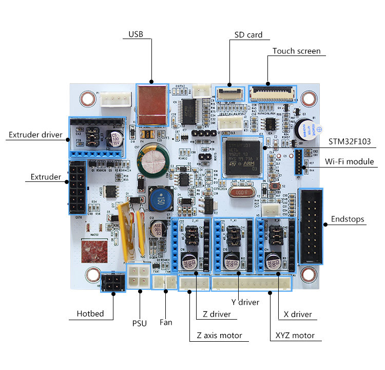
Interface Layout
Introduction to the Interfaces
1. PSU: output voltage 12V
2. Hotbed interface:
1, 2 for hotbed; 3,4 for the wire of measuring hotbed temp.
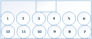
3. Extruder interface:
1, 2, 11, 12 for extruder motor; 3,4 for extruder fan and air blower; 9, 10 for filament sensor; 5,6 for the wire of heating the extruder; 7, 8 for the wire of measuring extruder temp.
4. LCD interface: connected with LCD display
5. SD card interface: connected with SD card
6. Endstop interface: X_min/X_max, Y_min/Y_max, Z_min/Z_max
1, 2, 3 for Z_min; 16, 17, 18 for Z_max; 4, 5, 6 for Y_min; 14, 15, 16 for Y_max; 7, 8, 9 for X_min; 10, 11, 12 for X_max.
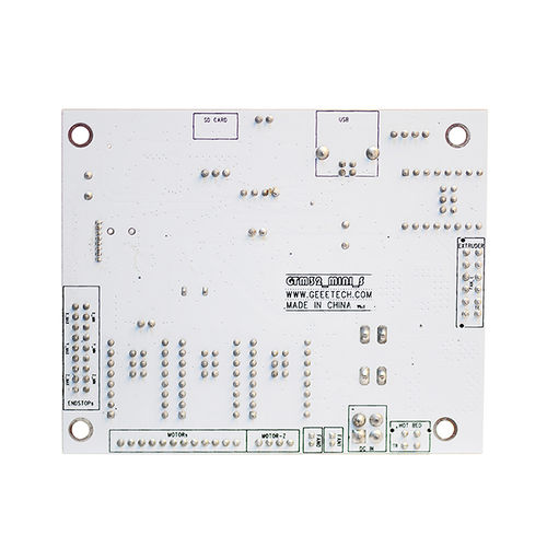
7. XYZ motor: connected with the stepper motor for each axis (the sequence can be found on the back of the board).
8. Fan interface: for PWM fan, PH2.0-2 pin
9. USB interface: Connecting the USB cable with your computer.
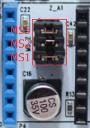
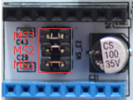
Subdivision of Stepper Motor
Use jumper caps to subdivide stepper motor. When jumper cap is plugged, it is ON.
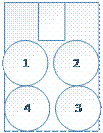
X,Y,Z axis stepper motors
Extruder stepper motors
Detailed settings are as follows.
Subdivision on the basis of A4988 stepper driving module.
Turn ON/OFF Subdivision
MS1 MS2 MS3
OFF OFF OFF full step
ON OFF OFF 1/2 step
OFF ON OFF 1/4 step
ON ON OFF 1/ 8 step
ON ON ON 1/16 step
Development Environment Setting
Interface Connecting and Setting
Note:
Pay attention to the Plus-n-Minus of the power connector, reverse connection can cause irrevocable damages.
A4988 should also be connected to the right port, mismatches and revered directions can cause damage to the main board. Please notice the color of the pins and connect the same colored pins together. If some pins are not color-labelled, pleased follow the picture below.
Install Software
Download FT232RL driver.
http://www.ftdichip.com/Drivers/CDM/CDM%20v2.12.00%20WHQL%20Certified.exe
After downloading, double-click the .exe file to finish the installation.
How to Install firmware
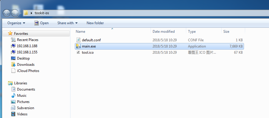
1. Download “toolkit-os” and upzip the file. Here is the link Firmware-download-tool
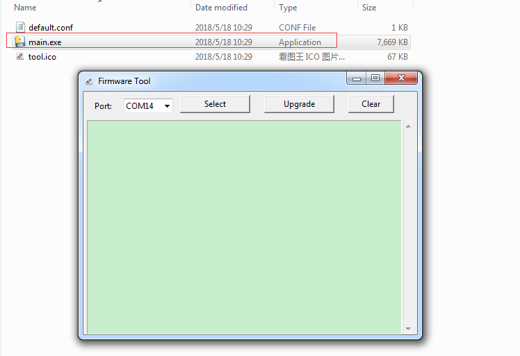
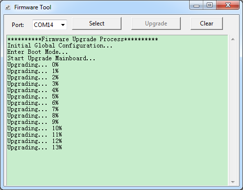
2. Connect your 3D printer with a computer. Double click “main.exe” to start upgrading the firmware for GTM32 control board. A window will pop up, showing the COM port for your 3D printer.
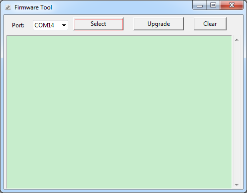
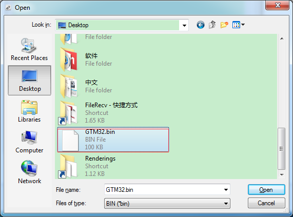
3. Click “Select” to choose the new firmware you’ve written, for instance, “GTM32.bin”.
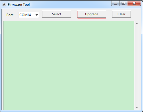
4. Click “Upgrade” and the upgrading will start automatically.
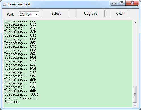
5. When the firmware is upgrade successfully, you will see the following window. Close the window to finish the whole process.
Open Source Firmware
Quick Start
FAQ
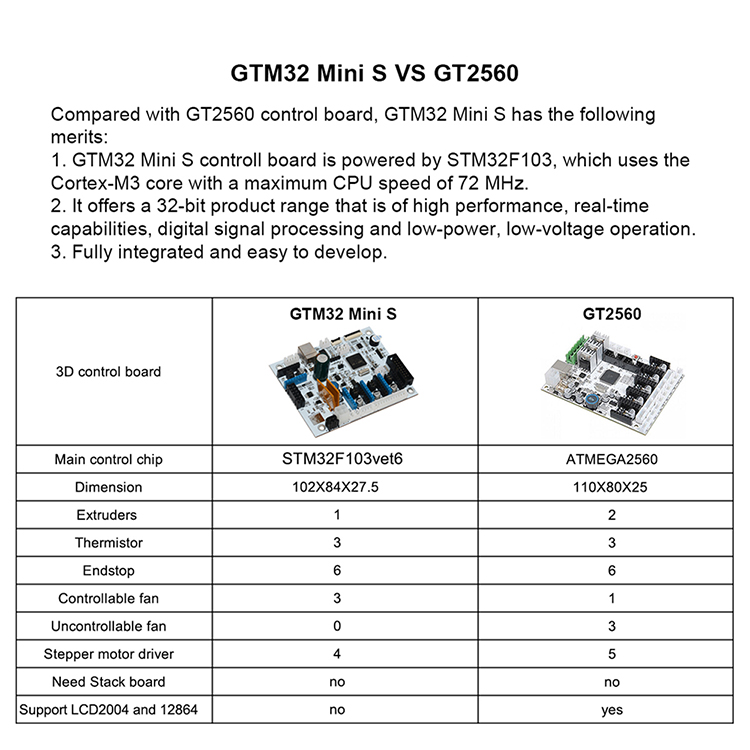
a. How many extruders do GTM32 control board support?
A: One extruder at best.
b. What’s the output voltage for GTM32 control board?
A: 12V.
c. Are there other ways to adjust the program?
A: The control board provides SWD interface, which enables you to simulate debug the firmware via Keil, IAR, etc. software.
d. How can I flash the program via USB connectivity?
A: There is a jumper interface on the “Booto” of the control board. Connect the jumper and use Flash Loader Demo to flash it.
e. What are the features of GTM32 control board?
A: Supporting auto-leveling with 3DTouch and capacitive proximity sensor; compatible with WiFi module to remote control your 3D printer; featuring serial full-color touch screen; supporting two Z axis stepper motors connected in parallel.
