Difference between revisions of "APM 2.52 Flight Controller Board"
(→Hardware Specification) |
(→Hardware Specification) |
||
| Line 26: | Line 26: | ||
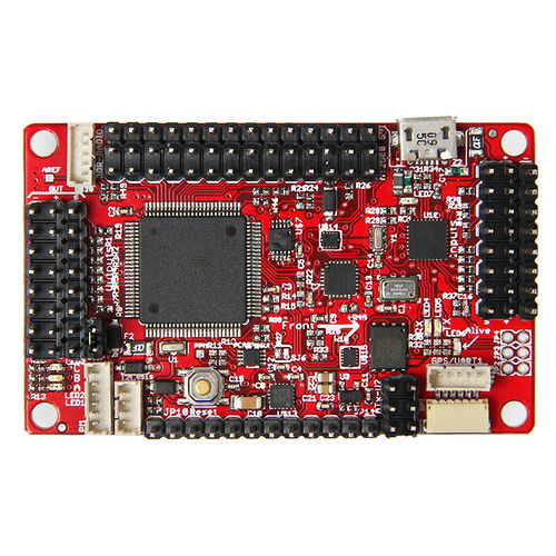
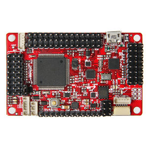
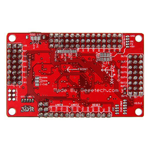
==Hardware Specification== | ==Hardware Specification== | ||
| − | [[File: | + | [[File:10.jpg|300px|]] [[File:APM 2.52 FRONT.jpg|300px|]] |
| − | [[File:APM 2.52 FRONT.jpg| | ||
'''APM2.52 Hardware Configuration''' | '''APM2.52 Hardware Configuration''' | ||
Revision as of 00:58, 18 August 2014
Contents
Introduction
APM is a open source flight control system, it is a multifunction system that can support quadrocopter, as well as aircrafts of fixed -wing, three-axis, 6-axis,8 –axis etc. APM flight control is a rather mature technique with formidable capabilities: it supports GPS designated cruise and automatic return; supports data transmission to realize the remote receiving of real-time data from the aircraft; supports pan-tilt control technique of professional cameras to ensure anti-vibration aerial photograph; supports peripheral interfaces as airspeed meter and galvanometer to ensure stable flight and low voltage protection of voltage detection in real time.
The APM2.52 Control Board is used for make UAV. This version is ready to use, with no assembly required. It allows the user to turn any fixed, rotary wing or multirotor vehicle (even cars and boats) into a fully autonomous vehicle, capable of performing programmed GPS missions with waypoint.
Features
1. Adapts PPM decoder chip- Atmega32U2 to take charge of the surveillance and controlling of PWM signal of mode channel so as to switch between manual mode and other modes, thus improving the security of the whole system.
2. The directional data provided by the inertial measurement unit (two-axis gyro and single-axis gyro) and triaxial accelerometer (to measure the speed of three axes and accelerate the speed), cooperating with the three axis magnetometer or GPS can be corrected to realize directional cosine algorithm and calculate the attitude of aircraft.
3. Integrated with MPU6000 (three-axis gyroscope + triaxial accelerometer), MS5611 berometer and HMC5883L three axis electronic compass.
4. Supports data transmission to realize the remote receiving of real-time data from the aircraft.
5. Supports pan-tilt control technique of professional cameras to ensure anti-vibration aerial photograph.
6. Supports airspeedometer to measure the airspeed of aircraft.
7. Supports airspeedometer to ensure stable flight and low voltage protection of voltage detection in real time.
8. Integrated with 12-bite high-precision AD chip which can convert the analog voltage output by airspeedometer and the temperature output by three-axis gyroscope, triaxial accelerometer and dual-axis gyroscope into digital value.
Hardware Specification
APM2.52 Hardware Configuration
- ATMEGA2560 microcontroller
- MPU6000 3-axis gyroscope and 3-axis accelerometer
- MS5611 pressure sensor
- HMC5883L 3-axis Magnetometer
NOTE:
Your APM 2.5 board is designed to be powered by the included Power Module via the Power Port connector. You can, however, power it from an ESC or some other external 5v source, although that can be less reliable. If you do choose to use an alternative power source, you need to put the little jumper that came in the bag on JP1 pins, next to the "new diode" marked at the left above. If you are not powering the board from an external source, the JP 1 jumper should be off (this is the normal configuration) If you want to explore other alternative power schemes, a guide is in the Appendix here.
Assembly
- Assemble your ArduCopter frame
You can built your frame by yourself or buy it from http://store.3drobotics.com/
- Connecting your RC input and motors
More details refer to http://code.google.com/p/arducopter/wiki/APM2RC
- Install Mission Planner and download firmware
More details refer to http://code.google.com/p/arducopter/wiki/AC2Installation
- Configure RC and Fight Mode
More details refer to http://code.google.com/p/arducopter/wiki/AC2_First
Flying
Flight Test Process
! Warning ! Read This Safety Section Before Flying - [1]Bold text
To Test Loiter and Altitude Hold:
1.Set up your APM so that Stabilize mode is at one extreme of your three-position mode select switch on your RC transmitter, Alt Hold mode is in the middle and Loiter mode is in the third position.
2.First, it´s important that Stabilize Mode is working OK. Set the Mode switch to Stabilize, turn on the transmitter and connect your battery. Wait until the GPS gets a lock. (Both the Blue GPS LED and the Blue C LED on the APM should be on and solid before arming and taking off). (It is even better to wait a bit longer to allow the GPS acquire additional satellites.) Note! the UBLOX GPS works differently On the UBLOX GPS the LED on the GPS module is off during satellite acquistion and on blinking when the satellite is acquired.
3.Start flying in Stabilize mode. Make sure you can take off, fly comfortably, and land. If you find it tilting, land and run the "Level" command in the Mission Planner. Fly through a whole battery like this, getting a feel for the controls (this will also calibrate your compass).
4.Now change batteries and try the auto modes. First, try Alt Hold at an altitude of about 20 meters. Your actual current throttle position is recorded as the "hovering point" when you switch to an altitude holding mode so it is important that you are not ascending or descending when you switch to Alt Hold. You should be able to fly around with the copter maintaining the same altitude, plus or minus a meter or so.
5.If that's working well, try Loiter. Just fly to a safe spot with lots of room around it and an altitude of about 20 meters and switch into Loiter. It should try to stay in that position, plus or minus about five meters.
6.When you have finished flying in Loiter or Alt Hold modes (or if anything unexpected or undesirable happens)switch back to Stabilize mode and land. (You cannot land and turn the motors off in Loiter or Alt Hold mode.)
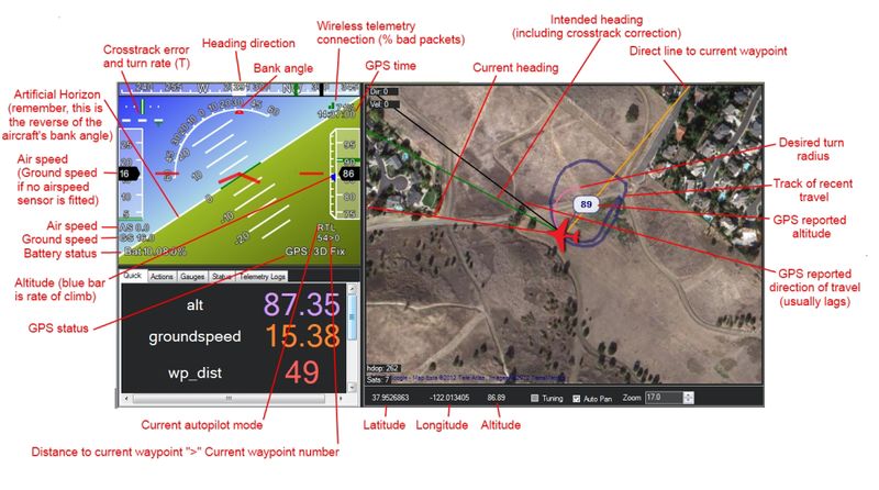
APM Mission Planner GCS
The APM Mission Planner that we use for most APM setup and mission scripting also includes an excellent built-in ground station.
Details on how to use it are [2].
LED Describtion
- LED A:It gleamed on behalf of the flight control is Disarm (inactive) state, shake will not start the motor control device of throttle. Only keep the remote controller rudder to the right more than 4 seconds to activate A light into light, said the current in the activated state, can fly. In debugging, moves on the ground, to ensure that A lamp in A blink state, lest appear dangerous.
- LED B:Ignore
- LED C: Indicates the status of GPS.If the satellite positioning, GPS has found and the LED light.We haven't the GPS positioning, flicker;If there is no GPS, the lights go out.Using GPS flight, should be after electrify until a blue light and then take off.
- LED RX TX:In data transmission when rapid flashing, such as ground station software connected with USB cable and computer, or when digital radio communication;
- LED Alive:Whether power or USB connect,it will light all the time.
Documents
3-axis Gyro
3-axis Accelerometer
3-axis Digital Compass
High Resolution Altimeter


