Difference between revisions of "NanoPC"
(→Nano PC Hardware Feature) |
(→Introduction) |
||
| Line 1: | Line 1: | ||
== Introduction == | == Introduction == | ||
| + | |||
[[File:NanoPC1.jpg]] | [[File:NanoPC1.jpg]] | ||
| Line 11: | Line 12: | ||
=== Nano PC Board === | === Nano PC Board === | ||
| + | |||
The Nano PC standard version integrates 1G DDR3 RAM and 4G eMMC flash memory. | The Nano PC standard version integrates 1G DDR3 RAM and 4G eMMC flash memory. | ||
| Line 17: | Line 19: | ||
[[File:NanoPC1.jpg]] | [[File:NanoPC1.jpg]] | ||
| − | + | * '''CPU''' | |
| + | ** Samsung Quad-Core Exynos 4412, based on Cortex-A9, 1.5GHz. | ||
| + | ** Integrated ARM Mali-400 Dual-Core GPU. | ||
| + | ** Elegent 2D/3D graphic accelaration. | ||
| + | ** Up to 1080p@30fps hard decoded video playing, support MPEG4, H.263, H.264 etc. | ||
| + | ** Up to 1080p@30fps hard decoded (Mpeg-2/VC1) video input. | ||
| + | * '''DDR3 RAM''' | ||
| + | ** 1G. | ||
| + | ** 32bit data bus, single channels. | ||
| + | ** 400 M Hz. | ||
| + | * '''FLASH''' | ||
| + | ** eMMC Flash: 8GB. | ||
| + | * '''LCD''' | ||
| + | ** LCD interface : 41Pin, 0.5mm spacing, compatible with Mini2440/Tiny4412/Mini210S LCD, supports one wire precise touching. | ||
| + | ** HDMI high definition interface (1.4A). | ||
| + | ** LCDs supported from 3.5” to 12.1” , HD. | ||
| + | * '''Network''' | ||
| + | ** 10/100M Ethernet interface(RJ45) using DM9621. | ||
| + | * '''Standard Configuration''' | ||
| + | ** 1 x microUSB Slave-2.0. | ||
| + | ** 1 x 3.5mm stereotype audio output. | ||
| + | ** 2 x USB Host 2.0. | ||
| + | ** 1 x 5V power input. | ||
| + | * '''On Board Hardware Resource''' | ||
| + | ** 1 x backup battery for on board real time clock. | ||
| + | ** 2 x LED. | ||
| + | ** 2 x User button. | ||
| + | ** 1 x Reset button. | ||
| + | ** 1 x On-board microphone. | ||
| + | ** 1 x Infrared receiver. | ||
| + | * '''External Resource''' | ||
| + | ** 1 x TTL. | ||
| + | ** 2 x GPIO. | ||
| + | ** 1 x MIPI camera interface. | ||
| + | ** 1 x Digital sensor. | ||
| + | * '''Power''' | ||
| + | ** 5V. | ||
| + | * '''PCB Dimension''' | ||
| + | ** Eight layered board. | ||
| + | ** Dimension: 100 x 60 (mm). | ||
| + | * '''OS''' | ||
| + | ** Android 4.0/4.2. | ||
| + | ** Ubuntu-1204. | ||
| + | ** Linux + Qt/Embedded-4.8.5. | ||
| + | |||
| + | == Get Started == | ||
| + | |||
| + | We provide various OS image files. Users can flash those files to the board via an SD card. We will guide you through these steps in this chapter. | ||
| + | |||
| + | |||
| + | === Burning Superboot to SD Card === | ||
| + | |||
| + | In order to boot from an SD card, you need to burn BIOS to it. FriendlyARM offers a flashing utility: SD-Flasher.exe which can burn our Bootloader (Superboot4412.bin) to an SD card. | ||
| + | |||
| + | We tested the following steps on Windows7. | ||
| + | |||
| + | Note: users complained that some notebook’s integrated SD card reader cannot work properly with card burning or reading. So far we haven’t encountered this issue and we suggest that you should try a common card reader in this case. | ||
| + | Our SD-Flasher.exe formats a 130M space for the bootloader therefore an SD card whose memory is less than 256M cannot work and we recommend using one whose memory is at least 4G. | ||
| + | |||
| + | Step1: launch the SD-Flasher.exe in your shipped CD (under “\tools\”). Note: this program should be run as “administrator”. | ||
| + | |||
| + | [[File:NanoPC4.jpg]] | ||
| + | |||
| + | When the utility is launched a message box will pop up “Select your Machine”, please select “Mini4412/Tiny4412”: | ||
| + | |||
| + | [[File:NanoPC5.jpg]] | ||
| + | |||
| + | Below is the dialog you will see after it is started. Note: the “ReLayout” is enabled | ||
| + | and we will format the SD card with this function. | ||
| + | |||
| + | [[File:NanoPC6.jpg]] | ||
| + | |||
| + | Step2: click on[[File:NanoPC7.jpg]]to select your bootloader file | ||
| + | |||
| + | [[File:NanoPC8.jpg]] | ||
| + | |||
| + | Step3: insert a FAT32 SD card into your host’s SD card socket (you can also use a USB card reader to connect to a PC), ''backup your data in the card'' and click on “Scan”, all recognized SD cards will be listed. | ||
| + | |||
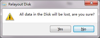
| + | Step4: click on “ReLayout”, the following dialog will pop up prompting you that the data in your card will be lost. Just click on “Yes” | ||
| + | |||
| + | [[File:NanoPC9.jpg]] | ||
| − | + | After formatting is done you will be directed back to the main menu. Click on “Scan”, you will see that a “FriendlyARM” section available. | |
| − | |||
| − | |||
| − | |||
| − | |||
| − | |||
| − | |||
| − | |||
| − | |||
| − | |||
| − | |||
| − | |||
| − | |||
| − | |||
Revision as of 10:11, 28 April 2014
Contents
Introduction
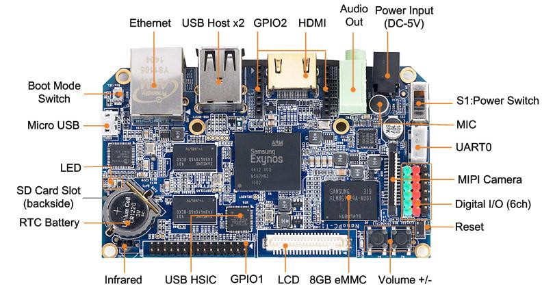
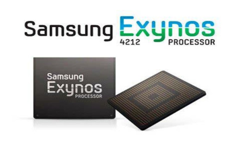
The Nano PC board is a Cortex-A9 embedded processing board that uses the Samsung Exynos4412 Quad-Core System On Chip (SOC).
The Exynos4412 integrates the Mali-400 MP GPU graphic engine with hardware support for 3D and can drive video playing on screens up to 1080P. These features make it easily and widely used in MID development, Android notepads, auto electronic devices, industrial applications, GPS systems and multimedia systems.
Nano PC Board
The Nano PC standard version integrates 1G DDR3 RAM and 4G eMMC flash memory.
Nano PC Hardware Feature
- CPU
** Samsung Quad-Core Exynos 4412, based on Cortex-A9, 1.5GHz.
** Integrated ARM Mali-400 Dual-Core GPU.
** Elegent 2D/3D graphic accelaration.
** Up to 1080p@30fps hard decoded video playing, support MPEG4, H.263, H.264 etc.
** Up to 1080p@30fps hard decoded (Mpeg-2/VC1) video input.
- DDR3 RAM
** 1G.
** 32bit data bus, single channels.
** 400 M Hz.
- FLASH
** eMMC Flash: 8GB.
- LCD
** LCD interface : 41Pin, 0.5mm spacing, compatible with Mini2440/Tiny4412/Mini210S LCD, supports one wire precise touching.
** HDMI high definition interface (1.4A).
** LCDs supported from 3.5” to 12.1” , HD.
- Network
** 10/100M Ethernet interface(RJ45) using DM9621.
- Standard Configuration
** 1 x microUSB Slave-2.0.
** 1 x 3.5mm stereotype audio output.
** 2 x USB Host 2.0.
** 1 x 5V power input.
- On Board Hardware Resource
** 1 x backup battery for on board real time clock.
** 2 x LED.
** 2 x User button.
** 1 x Reset button.
** 1 x On-board microphone.
** 1 x Infrared receiver.
- External Resource
** 1 x TTL.
** 2 x GPIO.
** 1 x MIPI camera interface.
** 1 x Digital sensor.
- Power
** 5V.
- PCB Dimension
** Eight layered board.
** Dimension: 100 x 60 (mm).
- OS
** Android 4.0/4.2.
** Ubuntu-1204.
** Linux + Qt/Embedded-4.8.5.
Get Started
We provide various OS image files. Users can flash those files to the board via an SD card. We will guide you through these steps in this chapter.
Burning Superboot to SD Card
In order to boot from an SD card, you need to burn BIOS to it. FriendlyARM offers a flashing utility: SD-Flasher.exe which can burn our Bootloader (Superboot4412.bin) to an SD card.
We tested the following steps on Windows7.
   Note: users complained that some notebook’s integrated SD card reader cannot work properly with card burning or reading. So far we haven’t encountered this issue and we suggest that you should try a common card reader in this case.
   Our SD-Flasher.exe formats a 130M space for the bootloader therefore an SD card whose memory is less than 256M cannot work and we recommend using one whose memory is at least 4G.
Step1: launch the SD-Flasher.exe in your shipped CD (under “\tools\”). Note: this program should be run as “administrator”.
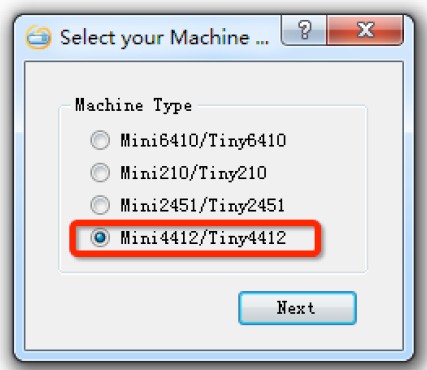
When the utility is launched a message box will pop up “Select your Machine”, please select “Mini4412/Tiny4412”:
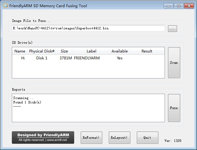
Below is the dialog you will see after it is started. Note: the “ReLayout” is enabled and we will format the SD card with this function.
Step2: click on![]() to select your bootloader file
to select your bootloader file
Step3: insert a FAT32 SD card into your host’s SD card socket (you can also use a USB card reader to connect to a PC), backup your data in the card and click on “Scan”, all recognized SD cards will be listed.
Step4: click on “ReLayout”, the following dialog will pop up prompting you that the data in your card will be lost. Just click on “Yes”
After formatting is done you will be directed back to the main menu. Click on “Scan”, you will see that a “FriendlyARM” section available.
