Difference between revisions of "Geeetech Mizar S 3D Printer"
(→How to replace a hotend and a nozzle) |
(→The consumables don't stick to the hot bed) |
||
| (99 intermediate revisions by the same user not shown) | |||
| Line 1: | Line 1: | ||
| − | ==Introduction== | + | ==Printer Introduction== |
| + | Geeetech Mizar S is a very good 3D printer with a medium print volume on the market. It has many premium features such as the automatic print bed leveling and the flexible print bed, it is also very well suited for beginners. | ||
| − | + | Mizar S uses a dual gear Bowden extruder, that is lightweight and compact in design, allowing higher speeds and generating less vibration. The extruder of the Mizar S has two drive gears. This gives greater extrusion force and control over the filament than standard Bowden extruders with only one active drive gear. | |
| + | The print bed of the Geeetech Mizar S doesn’t have any screws with which you can manually change the tilt. Instead, the print bed is mounted stationary and the print head has a built-in sensor that allows it to measure the distance to the print bed. | ||
| − | + | A dual Z-axis in a 3D printer increases accuracy because there is a stepper motor on each side of the Z-axis to move the X-axis in the Z-direction. This results in a more stable movement in the Z direction, which leads to higher accuracy when printing objects. | |
| + | [[File:W7.png]] | ||
| − | |||
| + | <big>Main Specification</big> | ||
| − | + | '''Printer Type''' FDM | |
| + | '''Layer Thickness''' 0.1-0.3 mm | ||
| + | |||
| + | '''Printing Material''' PLA,ABS, PETG, Silk PLA, Wood Polymer | ||
| + | |||
| + | '''Building Platform Volume''' 255*255*260 mm | ||
| + | |||
| + | '''Auto-leveling''' Yes | ||
| + | |||
| + | '''Break Resuming''' Yes | ||
| + | |||
| + | '''Preheat time(110℃)''' 7 min | ||
| + | |||
| + | '''Nozzle Diameter''' 0.4 mm | ||
| + | |||
| + | '''Positioning Precision''' X axis: 0.011 mm;Y axis: 0.011 mm;Z axis: 0.0025 mm; | ||
| + | |||
| + | '''Printing Accuracy''' ±0.1 mm | ||
| + | |||
| + | '''Printing Speed''' 10~150 mm/S; recommend 60~80 mm/s | ||
| + | |||
| + | '''Display Screen''' 3.5” Colorful Touch Screen | ||
| + | |||
| + | '''Operating System''' Windows, Mac, Linux, | ||
| + | |||
| + | '''Slicing Software''' Repetier-Host, EasyPrint Lite, Cura | ||
| + | |||
| + | '''Supported File Format''' .gcode | ||
| + | |||
| + | '''Hotbed Max. Temperature''' 110 ℃ | ||
| + | |||
| + | '''Extruder Max. Temperature''' 250 ℃ | ||
| + | |||
| + | '''Environmental Temperature''' 10-40 ℃ | ||
| + | |||
| + | |||
| + | <big>Electrical Parameter</big> | ||
| + | |||
| + | '''Power Input''' 115/230 V AC, 50/60 Hz | ||
| + | |||
| + | '''Power Output''' DC 24 V-15 A Max, 360 W | ||
| + | |||
| + | '''Connectivity Interface''' 1*TF Card, 1*USB cable | ||
| + | |||
| + | '''Power Supply Unit Certification''' CE, FCC,ROSH | ||
| + | |||
| + | |||
| + | <big>Mechanical Parameter</big> | ||
| + | |||
| + | '''Printing Size''' 255*255*260 mm | ||
| + | |||
| + | '''Net Weight(kg)''' 8.9 kg | ||
| + | |||
| + | '''Gross Weight(kg)''' 11.2 kg | ||
| + | |||
| + | '''Printer Whole Size''' 362(W)*377(L)*653(H)mm | ||
| + | |||
| + | '''Packing Dimension''' 522(L)*482(W)*310(H)mm | ||
| + | |||
| + | Watch the [https://www.youtube.com/watch?v=KjI1iDQFy5A unboxing video] and [https://www.geeetech.com/download.html?version_id=490 user manual] before assembling the printer. | ||
| + | |||
| + | ==Printer Maintenance== | ||
| + | |||
| + | === '''How to replace PSU'''=== | ||
| + | |||
| + | |||
| + | {| class="wikitable" | ||
| + | |- | ||
| + | ! Tools necessary for this guide | ||
| + | |- | ||
| + | | Allen keys - 2.5/3 mm | ||
| + | |||
| + | Philips screwdriver for PSU cables | ||
| + | |||
| + | |} | ||
| + | |||
| + | The power supply is available in our website: [https://www.geeetech.com/mizar-s-printer-power-supply-350w-24v-p-1351.html Mizar S power supply] | ||
| + | |||
| + | Watch the video tutorial: [https://www.youtube.com/watch?v=9c3J2QsOtH0 How to replace the power supply of the Mizar S] | ||
| + | |||
| + | Turn the printer off and unplug it from the socket. | ||
| + | |||
| + | [[File:M32.png]] | ||
| + | |||
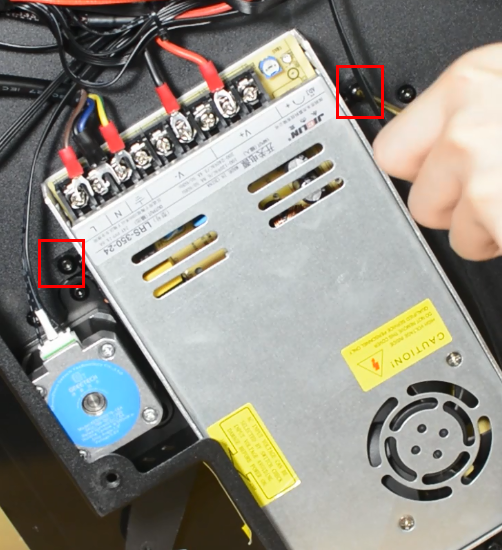
| + | Release and remove the two screws that secure the PSU. | ||
| + | |||
| + | [[File:M48.png]] | ||
| + | |||
| + | Remove the bottom cover, unplugging the cooling fan. | ||
| + | |||
| + | [[File:M14.png]] | ||
| + | |||
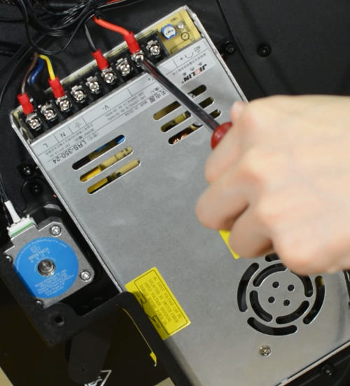
| + | Using a Philips screwdriver release all five screws. | ||
| + | |||
| + | [[File:M49.png]] | ||
| + | |||
| + | Release and remove the two screws that holding the PSU and make sure you hold it before releasing the last screw. | ||
| + | |||
| + | [[File:M50.png]] | ||
| + | |||
| + | Assembling the new PSU. | ||
| + | |||
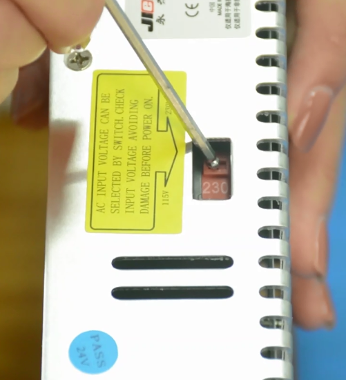
| + | '''Ensure that the DIP switch of the power supply is adjusted to the right voltage!''' | ||
| + | |||
| + | [[File:M53.png]] | ||
| + | |||
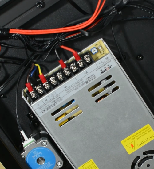
| + | '''Please triple-check you have connected the cables correctly!''' | ||
| + | |||
| + | '''There is a risk of damaging the PSU or the printer itself, if the cables are connected incorrectly or not tightened properly!''' | ||
| + | |||
| + | [[File:M51.png]] | ||
| + | |||
| + | Tighten the two screws. | ||
| + | |||
| + | [[File:M52.png]] | ||
| + | |||
| + | Plug the cooling fan back in and secure the base cover with screws. | ||
=== '''How to replace a hotend '''=== | === '''How to replace a hotend '''=== | ||
| + | Mizar S hotend kit is available in our website: [https://www.geeetech.com/mizar-s-3d-printer-hotend-kit-p-1345.html Mizar S hotend kit] | ||
| + | |||
| + | Watch video tutorial: [https://www.youtube.com/watch?v=bA21L4ziTbA How to replace the hotend of Mizar S] | ||
{| class="wikitable" | {| class="wikitable" | ||
| Line 34: | Line 156: | ||
Craft knife or equivalent | Craft knife or equivalent | ||
|} | |} | ||
| + | |||
| + | |||
| + | |||
| + | '''Step 1 Preparing''' | ||
| + | |||
| + | Preheat the nozzle to 220 Celsius from the LCD menu, then unload the filament from the hotend. | ||
| + | |||
| + | Remove the Teflon tube from the hotend. | ||
| + | |||
| + | [[File:M1.png]] | ||
| + | |||
| + | <big>'''Before moving to step 2, remember to turn the printer off and unplug it from the socket!'''</big> | ||
| + | |||
| + | [[File:M32.png]] | ||
| + | |||
| + | '''Step 2 Disassembling the hotend''' | ||
| + | |||
| + | Remove the hotend housing and disconnect the hotend thermistor. | ||
| + | |||
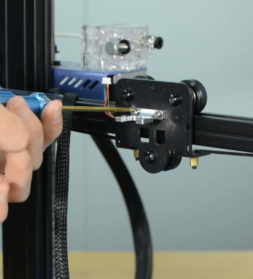
| + | Release and remove the two screws that secure the hotend, then unplug all the cables on the extension board. | ||
| + | |||
| + | [[File:M3.png]] | ||
| + | |||
| + | Remove the extension board and the part cooling fan. | ||
| + | |||
| + | [[File:M4.png]] | ||
| + | |||
| + | [[File:M5.png]] | ||
| + | |||
| + | Remove the strain gauge. | ||
| + | |||
| + | [[File:M12.png]] | ||
| + | |||
| + | '''Step 3 Disconnecting the hotend cables''' | ||
| + | |||
| + | Remove the bottom cover and disconnect the cooling fan. | ||
| + | |||
| + | [[File:M13.png]] | ||
| + | |||
| + | [[File:M14.png]] | ||
| + | |||
| + | Disconnect the heater cartridge. | ||
| + | |||
| + | [[File:M15.png]] | ||
| + | |||
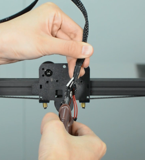
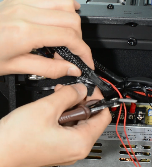
| + | Cut off the heat-shrink tubing from the connection wire. Avoid cutting the cable. | ||
| + | |||
| + | [[File:M7.png]] | ||
| + | |||
| + | [[File:M8.png]] | ||
| + | |||
| + | Remove the old heater cartridge. | ||
| + | |||
| + | [[File:M9.png]] | ||
| + | |||
| + | |||
| + | '''Step 4 Install the new hotend kit''' | ||
| + | |||
| + | Fix the new strain gauge. | ||
| + | |||
| + | [[File:M10.png]] | ||
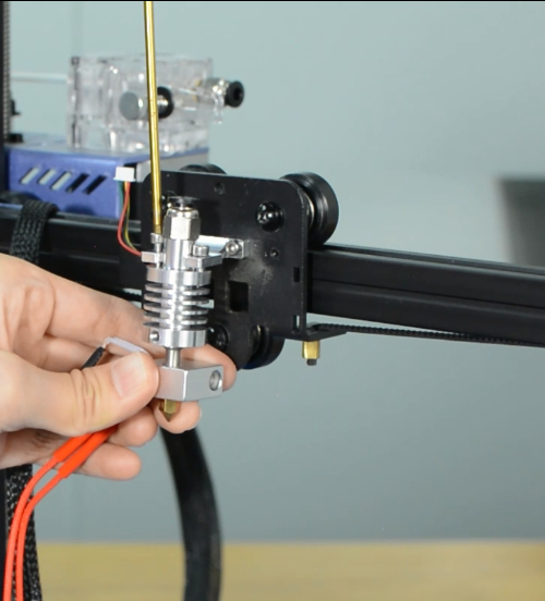
| + | |||
| + | Install the new hotend. | ||
| + | |||
| + | [[File:M11.png]] | ||
| + | |||
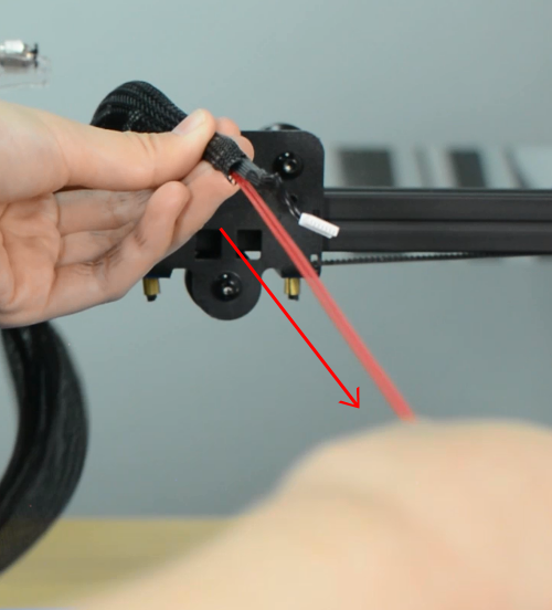
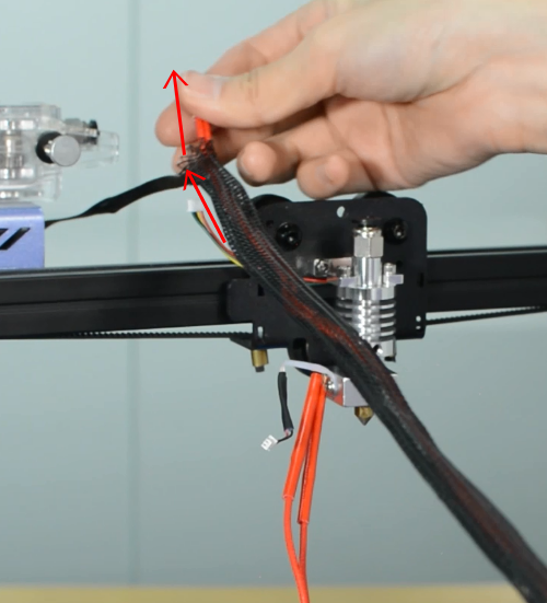
| + | Run the cables of heater cartridge through the textile sleeve. | ||
| + | |||
| + | [[File:M16.png]] | ||
| + | |||
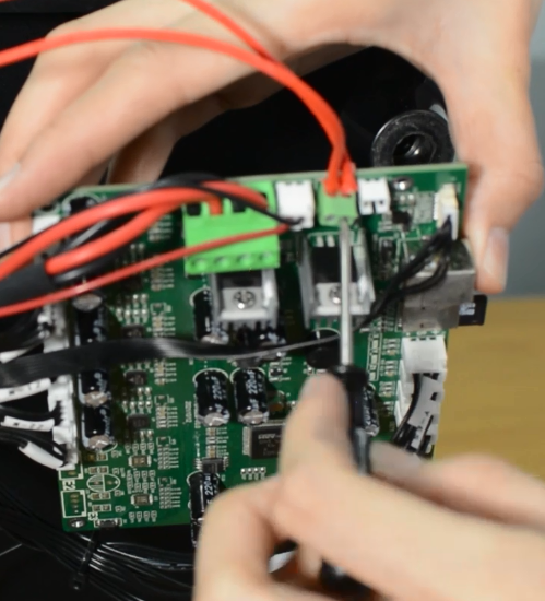
| + | Insert the both heater cables into the connector. | ||
| + | |||
| + | [[File:M18.png]] | ||
| + | |||
| + | '''Make sure the cables are fully inserted and tightened!''' | ||
| + | |||
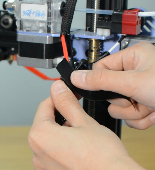
| + | Tighten the textile sleeve with electrical tape. | ||
| + | |||
| + | [[File:M19.png]] | ||
| + | |||
| + | [[File:M21.png]] | ||
| + | |||
| + | Tighten the zip ties and cut the remaining parts. | ||
| + | |||
| + | [[File:M23.png]] | ||
| + | |||
| + | Install the part cooling fan and extension board. | ||
| + | |||
| + | [[File:M24.png]] | ||
| + | |||
| + | Connect all the hotend cables to the extension board. | ||
| + | |||
| + | [[File:M25.png]] | ||
| + | |||
| + | '''Step 5 Install the PTFE tube''' | ||
| + | |||
| + | Take the razor or knife and carefully trim the tube. The Teflon ends should remain flat. '''Uneven ends may cause hotend to jam.''' | ||
| + | |||
| + | [[File:M27.png]] | ||
| + | |||
| + | Insert and push the new PTFE tube into the heatbreak all the way down. | ||
| + | |||
| + | [[File:M28.png]] | ||
| + | |||
| + | [[File:M29.png]] | ||
| + | |||
| + | Install the print head housing. | ||
| + | |||
| + | [[File:M30.png]] | ||
| + | |||
| + | Plug the cooling fan back in and secure the base cover with screws. | ||
| + | |||
| + | [[File:M31.png]] | ||
| + | |||
| + | It's done! Plug in the printer and turn it on to check whether the printer works properly. | ||
| + | |||
| + | [[File:M33.png]] | ||
| + | |||
| + | === '''How to replace a hotbed'''=== | ||
| + | |||
| + | |||
| + | {| class="wikitable" | ||
| + | |- | ||
| + | ! Tools necessary for this guide | ||
| + | |- | ||
| + | | Allen keys – 3 mm | ||
| + | |||
| + | Flat screwdriver tip width 2.5 mm | ||
| + | |||
| + | Diagonal pilers | ||
| + | |||
| + | Zip ties | ||
| + | |||
| + | |} | ||
| + | |||
| + | The hotbed is available in our website: [https://www.geeetech.com/mizar-s-3d-printer-heat-bed-full-fixed-hotbed-kit-p-1347.html Mizar S hotbed kit] | ||
| + | |||
| + | Watch video tutorial: [https://www.youtube.com/watch?v=MV9_2AdIz00 How to replace the hotbed of Mizar S] | ||
| + | |||
| + | '''Turn the printer off and unplug it from the socket!''' | ||
| + | |||
| + | [[File:M32.png]] | ||
| + | |||
| + | Remove the bottom cover, unplugging the cooling fan. | ||
| + | |||
| + | [[File:M14.png]] | ||
| + | |||
| + | Disconnect the hotbed cable and hotbed thermistor. | ||
| + | |||
| + | [[File:M54.png]] | ||
| + | |||
| + | [[File:M55.png]] | ||
| + | |||
| + | Release and remove the three screws of the Y-axis rail. | ||
| + | |||
| + | [[File:M58.png]] | ||
| + | |||
| + | Remove the hotbed from the printer. | ||
| + | |||
| + | [[File:M59.png]] | ||
| + | |||
| + | [[File:M60.png]] | ||
| + | |||
| + | Install the new hotbed kit and '''pay attention to how the Y-axis belt is installed''' as the pictures below. | ||
| + | |||
| + | [[File:M62.png]] | ||
| + | |||
| + | [[File:M63.png]] | ||
| + | |||
| + | Tighten the three screws. | ||
| + | |||
| + | [[File:M64.png]] | ||
| + | |||
| + | Connect the hotbed thermistor and hotbed cable. | ||
| + | |||
| + | [[File:M65.png]] | ||
| + | |||
| + | Plug the cooling fan back in and secure the base cover with screws. | ||
| + | |||
| + | === '''How to replace a screen'''=== | ||
| + | |||
| + | |||
| + | {| class="wikitable" | ||
| + | |- | ||
| + | ! Tools necessary for this guide | ||
| + | |- | ||
| + | | Allen keys - 2.5/3 mm | ||
| + | |||
| + | |} | ||
| + | |||
| + | The screen is available in our website: [https://www.geeetech.com/mizar-s-fdm-3d-printer-color-touch-screen-p-1338.html Mizar S touch screen] | ||
| + | |||
| + | Watch video tutorial: [https://www.youtube.com/watch?v=a8aIYq3w0mE How to replace the touch screen of Mizar S] | ||
| + | |||
| + | '''Turn the printer off and unplug the power cable!''' | ||
| + | |||
| + | [[File:M32.png]] | ||
| + | |||
| + | Remove the bottom cover, unplugging the cooling fan. | ||
| + | |||
| + | [[File:M14.png]] | ||
| + | |||
| + | Unplug the screen connector and put it to the side. | ||
| + | |||
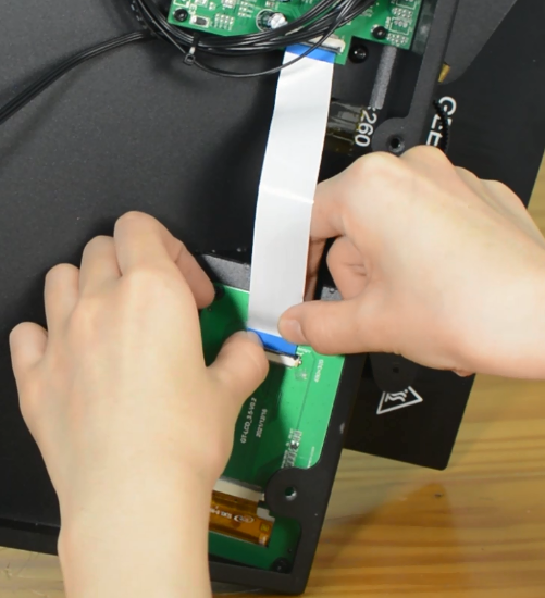
| + | [[File:M66.png]] | ||
| + | |||
| + | Release and remove four screws on screen. | ||
| + | |||
| + | Set the screws in place, tighten the screws. | ||
| + | |||
| + | Connect the LCD cable. | ||
| + | |||
| + | [[File:M67.png]] | ||
| + | |||
| + | Plug the cooling fan back in and secure the base cover with screws. | ||
| + | === '''How to replace a control board'''=== | ||
| + | |||
| + | |||
| + | {| class="wikitable" | ||
| + | |- | ||
| + | ! Tools necessary for this guide | ||
| + | |- | ||
| + | | Allen keys – 2.5/3 mm | ||
| + | |||
| + | Flat screwdriver tip width 2.5 mm | ||
| + | |||
| + | |} | ||
| + | |||
| + | The control board is available in our website: [https://www.geeetech.com/mizar-s-3d-printer-motherboard-control-board-p-1337.html Mizar S control board] | ||
| + | |||
| + | Watch video tutorial: [https://www.youtube.com/watch?v=UODntg9HJIU How to replace the control board of Mizar S] | ||
| + | |||
| + | '''Turn the printer off and unplug the power cable!''' | ||
| + | |||
| + | [[File:M32.png]] | ||
| + | |||
| + | Remove the bottom cover, unplugging the cooling fan. | ||
| + | |||
| + | [[File:M14.png]] | ||
| + | |||
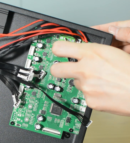
| + | Disconnecting all the cables. | ||
| + | |||
| + | [[File:M42.png]] | ||
| + | |||
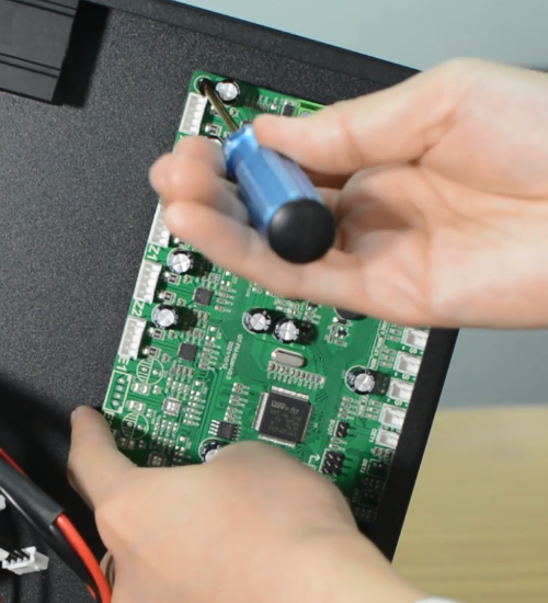
| + | Replace with a new control board and tighten the screws securely. | ||
| + | |||
| + | [[File:M43.png]] | ||
| + | |||
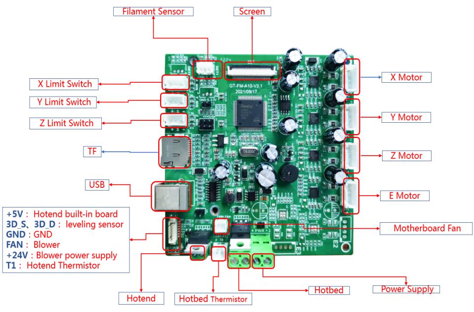
| + | Plug in all the connections as the picture below. | ||
| + | |||
| + | [[File:M26.png]] | ||
| + | |||
| + | Insert the cables of power supply and hotbed. Red wire is positive and black wire is negative. | ||
| + | |||
| + | '''Make sure the cables are fully inserted and tightened!''' | ||
| + | |||
| + | [[File:M45.png]] | ||
| + | |||
| + | [[File:M46.png]] | ||
| + | |||
| + | Connect the LCD cable. | ||
| + | |||
| + | [[File:M47.png]] | ||
| + | |||
| + | Plug the cooling fan back in and secure the base cover with screws. | ||
| + | |||
| + | It's done! Plug in the printer and turn it on to check whether the printer works properly. | ||
| + | |||
| + | === '''How to replace a filament sensor'''=== | ||
| + | |||
| + | The filament sensor will be worn out after long time use. We’ve uploaded a [https://www.geeetech.com/download.html?version_id=553 filament guide] on our website to fix this. | ||
| + | |||
| + | [[File:W40.png]] | ||
| + | |||
| + | And thanks to the 3D printer community, there’re lots of upgrade mods on the website for reference. | ||
| + | |||
| + | [https://www.thingiverse.com/thing:5654474 Geeetech Mizar S filament roller guide by by JTProuhet] | ||
| + | |||
| + | |||
| + | If there’s error on the screen prompts like “Change Filament” even filament has been uploaded, maybe the sensor is broken. You can test it by a multimeter. | ||
| + | |||
| + | Remember load a small piece of filament through the sensor before test. By touching each of the measurement leads of the multimeter to the two pins of the sensor, a signal (beep or 0 value on the multimeter screen) will indicate that the component is intact and therefore, should work. | ||
| + | |||
| + | [[File:W1.png]] | ||
=== '''How to clean the hotend and replace a nozzle'''=== | === '''How to clean the hotend and replace a nozzle'''=== | ||
| Line 54: | Line 460: | ||
|} | |} | ||
| − | === '''How to | + | The nozzle for Mizar S is available in our website: [https://www.geeetech.com/5pcs-nozzle-for-mizar-s-mizar-3d-printer-04mm-nozzle-screw-thread-m6-p-1352.html 5pcs* Nozzle for Mizar S] |
| + | |||
| + | Watch video tutorial: [https://www.youtube.com/watch?v=teRDQRRNHfA How to clean hotend and replace nozzle of Mizar S] | ||
| + | |||
| + | '''Step 1 Clean the hotend''' | ||
| + | |||
| + | Preheat the nozzle to 220 Celsius from LCD menu. | ||
| + | |||
| + | [[File:M34.png]] | ||
| + | |||
| + | Clean the surface of the nozzle with tweezers. | ||
| + | |||
| + | [[File:M35.png]] | ||
| + | |||
| + | Unload the filament from the hotend. | ||
| + | |||
| + | [[File:M36.png]] | ||
| + | |||
| + | Remove the Teflon tube from the hotend. | ||
| + | |||
| + | [[File:M37.png]] | ||
| + | |||
| + | Use a cleaner rod (1.5 mm diameter, 100 mm length) to push it in and out several times, making the clog out. Do not use excessive force. | ||
| + | |||
| + | [[File:M38.png]] | ||
| + | |||
| + | Use a needle to clean the nozzle. | ||
| + | |||
| + | [[File:M39.png]] | ||
| + | |||
| + | '''Step 2 Replace a nozzle''' | ||
| + | |||
| + | Turn the printer off. | ||
| + | |||
| + | Remove the print head housing. | ||
| + | |||
| + | Release the old nozzle with a 6mm spanner while holding the heater block in place with a 20mm spanner. | ||
| + | |||
| + | [[File:M40.png]] | ||
| + | |||
| + | Install the new nozzle and tighten it gently, but firmly. Do not use excessive force! | ||
| + | |||
| + | [[File:M41.png]] | ||
| + | |||
| + | Place the silicone sock for heater block. | ||
| + | |||
| + | Install the print head housing. | ||
| + | |||
| + | Insert and push the new PTFE tube into the heatbreak all the way down. | ||
| + | |||
| + | ==Trouble Shooting== | ||
| + | |||
| + | === '''Black screen '''=== | ||
| + | |||
| + | |||
| + | <big>Warning: Never install or unplug anything on a printer while it’s being powered!</big> | ||
| + | |||
| + | |||
| + | (a)Please check if the power supply is working normally. The red indicator on the switch should be light. And also check the fuse in the little black box, it should be complete without burns. Please measure the output voltage, which should be around 24 Volts. | ||
| + | |||
| + | [[File:W41.png]] | ||
| + | |||
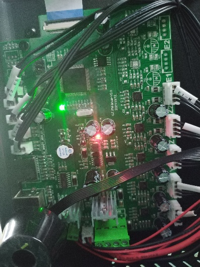
| + | (b)Please check if the control board is working normally. There’re one green LED and one red LED working as the picture shown below. Measure the input voltage of the control board, it should be around 24 Volts. | ||
| + | |||
| + | [[File:W48.png]] | ||
| + | |||
| + | (c)Make sure the screen is connected properly. | ||
| + | === '''Mintemp Error'''=== | ||
| + | |||
| + | The Mintemp error in 3D printers is a design feature within your firmware for safety in regard to temperature. When below a set temperature, the heater will be switched off due to possibly having a broken thermistor wire. It can be observed a negative the temperature on the LCD screen. | ||
| + | |||
| + | |||
| + | Check if the hot end connector and thermistor are connected properly as the pictures below. Check the hotend cables and thermistor, make sure they’re not broken or burn out. | ||
| + | |||
| + | [[File:W22.png]] | ||
| + | |||
| + | You can test the thermistor by a multimeter. If it fails to read the resistance, then the wire is broken. At room temperature, it should be 80 kΩ - 125 kΩ. | ||
| + | Or apply heat to the thermistor with a heater, blow-dryer or other heating device. | ||
| + | The resistance should decline steadily in seconds if it works. If not, replace it. | ||
| + | |||
| + | |||
| + | Another common reason behind getting the MINTEMP error is from being in a cold environment, especially in winter months. Your 3D printer is designed to have a minimum temperature that it can operate in as a safety feature. | ||
| + | === '''Update Firmware'''=== | ||
| + | |||
| + | Download the [https://www.geeetech.com/download.html?download_id=57 latest firmware] in our website | ||
| + | |||
| + | '''How to update:''' | ||
| + | |||
| + | 1.Put "bin” file and "assets” folder in TF card root directory, insert TF card into the printer. | ||
| + | |||
| + | 2.Turn on the printer, the screen will display the firmware upgrade progress bar. | ||
| + | |||
| + | 3.After the progress is complete, the printer starts to upgrade UI. | ||
| + | |||
| + | 4.Update is complete. | ||
| + | |||
| + | '''Notice:''' | ||
| + | |||
| + | '''1.After the upgrade, delete the bin file and assets folder in the TF card to prevent repeated upgrades.''' | ||
| + | |||
| + | '''2.Level the hotbed after the upgrade is complete.''' | ||
| + | |||
| + | === '''Automatic leveling failed'''=== | ||
| + | |||
| + | (a)Nozzle calibration failed | ||
| + | |||
| + | You should use a scraper against the nozzle and gently push up to make the nozzle “feel” the pressure. If this still fails, check if the strain gauge in the hotend is connected properly, and ensure the cables are not broken. | ||
| + | |||
| + | [[File:W29.png]] | ||
| + | |||
| + | (b)Homing failed | ||
| + | |||
| + | Check the X, Y and Z axes end stops, make sure they’re all connected properly. Note the photoelectric end stops on the Y and Z axes, which normally have a blue signal light. You can home the X, Y and Z axes one by one to check which axis is faulty. | ||
| + | |||
| + | [[File:W39.png]] | ||
| + | |||
| + | (c)The first layer is messy | ||
| + | |||
| + | Please clean the hotbed before printing, this will help to get a good adhesion. We recommend a thicker first layer, 0.3 mm is good. If these’re not helpful, please try to adjust the Z-offset. What’s more, you can try adjust the hotbed temperature, for example, the Geeetech wood PLA needs a lower hotbed temperature but PETG needs higher. | ||
| + | Consumables don't stick to the hot bed | ||
| + | |||
| + | === '''Material break detection wear'''=== | ||
| + | |||
| + | [[File:W57.png]] | ||
| + | |||
| + | Please add a section of pipe in front of the filament sensor to prevent wearing. | ||
| + | |||
| + | [[File:W58.png]] | ||
| + | |||
| + | === '''The printer cannot be turned on '''=== | ||
| + | |||
| + | 1.Please make sure you select the correct voltage first. | ||
| + | |||
| + | 2. Check that the motherboard is properly connected to the screen, as shown in Figure 1. Switch the mains on and the screen works as shown in Figure 2. | ||
| + | |||
| + | 3. The power supply is working normally as shown in Figure 3. | ||
| + | |||
| + | 4. Check whether the mainboard works properly, as shown in Figure 4. | ||
| + | |||
| + | [[File:W52.png]] [[File:W53.png]] | ||
| + | |||
| + | [[File:W54.png]] [[File:W55.png]] | ||
| + | |||
| + | [[File:W56.png]] | ||
| + | |||
| + | === '''The extruder keeps making a click sound'''=== | ||
| + | |||
| + | (a)Decrease the print speed. If the print speed is too fast, the extruder will push the filament too quickly. Filament may not have enough time to melt and even clog in the nozzle. A clogged nozzle will then exert pressure back on the extruder, resulting in clicking. For PLA, our recommended print speed is 60mm/s. | ||
| + | |||
| + | (b)Increase the print temperature. If the temperature is too low, it will not melt the filament properly. This can also clog the nozzle. As the extruder is no longer able to push the filament ahead, it starts “slipping”. | ||
| + | |||
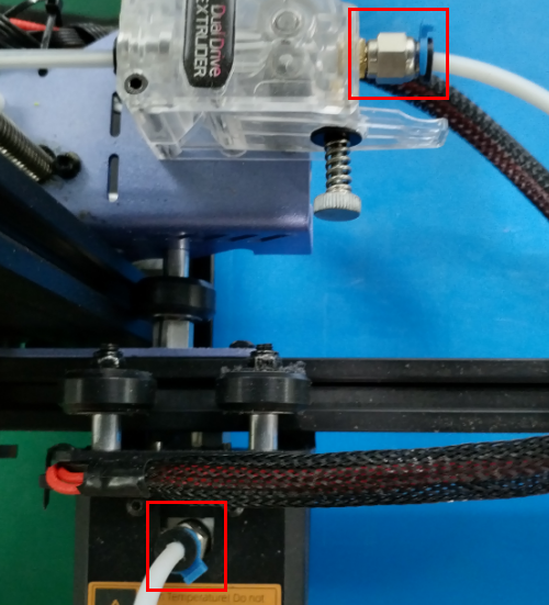
| + | (c)Check the pneumatic fittings. A loose coupling could therefore allow molten filament to leak into a gap between the tube and the nozzle. This will restrict the flow of the filament, causing the extruder keep clicking. | ||
| + | |||
| + | [[File:W47.png]] | ||
| + | |||
| + | (d)Change the extruder gear. After many hours of use, the teeth of the extruder may eventually wear out. Thus, it can no longer hold the filament, leading to filament slipping in the extruder. | ||
| + | |||
| + | (e)A low-tension extruder arm bar. If spring tension is too low, the extruder gear will not properly grip the filament. This leads to filament grinding. | ||
| + | |||
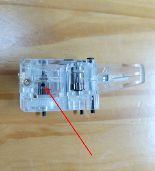
| + | (f)Check if the grub screw on the extruder gear. If the grub screw is loose, the gears will fail to grab the filament when feeding into the hotend. | ||
| + | |||
| + | [[File:W35.png]] | ||
| + | === '''The consumables don't fall off the Mylar'''=== | ||
| + | |||
| + | [[File:W59.png]] | ||
| + | |||
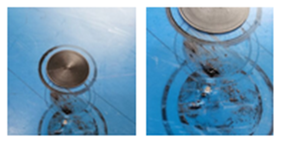
| + | Filament residues stick to Mylar sheets and are difficult to remove, usually because the nozzle is too close to the hot bed when printing the first layer, resulting in very thin extruded filaments. | ||
| + | The spring steel sheet is flexible and easy for part removal. But keep in mind that prints are easy to remove after the plate cools down. Don’t try to forcefully remove the object when the sheet is still hot. We do not suggest you use the adhesive on the sheet, because the adhesive is difficult to clean up and may have an opposite effect. | ||
| + | If there’re leftover residue on the sheet, preheat the hotbed to 80 degrees to make the plastic soft. Then use the wet cloth wiping the plate and gently scrap the residue off. | ||
| + | A dirty bed will cause poor first layer adhesion. You need to remove the dirt, leftover residue or oil from the bed surface. Isopropyl alcohol (IPA) 90%+ will help to degrease the platform. | ||
| + | |||
| + | === '''The consumables don't stick to the hot bed'''=== | ||
| + | |||
| + | 1.Nozzle is too close to the hotbed | ||
| + | |||
| + | Even though the extruder is working but no filament is depositing on the hotbed, Check if the nozzle is too close to the hotbed. Adjust the Z-offset value slightly will help. | ||
| + | |||
| + | 2.Print temperature is too low | ||
| + | |||
| + | Some filament needs more higher temperature, manually feed the filament, if it can not be extruded, please try increase the print temperature. | ||
| + | |||
| + | 3.The extruder is not working | ||
| + | |||
| + | Check if the grub screw on the extruder gear. If the grub screw is loose, the gear will fail to grab the filament when feeding into the hotend. Also check if the extruder motor is connected properly. | ||
| + | |||
| + | === '''The thickness of the first layer printed is uneven'''=== | ||
| + | |||
| + | [[File:W60.png]] | ||
| + | |||
| + | The thin area of the first layer is because the nozzle is too close to the hot bed, so that the filament is under extrusion. Please clean up the hot bed and adjust the value of Z-offset. Check out our YouTube channel for more details. It is recommended to set the initial layer height to 0.3mm and the initial layer speed to 20mm/s. | ||
| + | |||
| + | Geeetech Mizar S Z-offset Exquisite Leveling:https://www.youtube.com/watch?v=iuF_-HQl8HI&list=PLODCkot3GrigK0dnpjArzevcaKNLslUgP&index=6 | ||
| + | |||
| + | [[File:W61.png]] [[File:W62.png]] | ||
| + | |||
| + | === '''The print is brushed or leaked'''=== | ||
| + | |||
| + | [[File:W63.png]] | ||
| + | |||
| + | The drawing is the residual linear object left when the extruder crosses the open space. The common measure to solve this problem is to control the "withdrawal" function in the slice software. If the tap is opened in the slice, the consumables will be pulled back in the opposite direction for a distance before the sprinkler head is moved to the next point. When the product moves to the next point, the consumables will be squeezed out again. Although theoretically, it can be avoided, there are several problems in practice: | ||
| + | |||
| + | 1. Insufficient withdrawal distance | ||
| + | The most important setting in the return is the return distance, which determines how much plastic is drawn from the nozzle during the return. Usually, the more plastic the draw from the nozzle, the less obvious the drawing is. | ||
| + | |||
| + | 2. The withdrawal speed is too slow | ||
| + | Another important setting in the withdrawal is the speed of the withdrawal, which determines how fast the consumables are withdrawn. If the pump rate is too slow, the melted supplies will still flow out of the nozzle. If the withdrawal is too fast, the separation of the unmelted part and the melted part of the consumables may occur, or the extrusion wheel may bite off a piece of the consumables. | ||
| + | |||
| + | 3. The temperature is too high | ||
| + | If the temperature of the extrusion head is too high, the consumables in the nozzle will become very sticky, and it is easy to flow out of the nozzle, but if the temperature is too low, the consumables are more difficult to squeeze out. In the determination of the drawing distance and drawing speed are more appropriate, there is still a drawing situation, you can try to reduce the temperature of the extrusion head by 5-10 degrees Celsius. | ||
| + | |||
| + | 4, the suspended movement distance is too long | ||
| + | The suspended distance will also have a great impact on the drawing. The short distance movement, the melted consumables do not have enough time to flow out of the nozzle, but the long distance movement is very easy to produce the phenomenon of drawing. Some slicing software has relevant Settings, which can avoid the long distance movement. | ||
| + | |||
| + | === '''Underextrusion and overextrusion'''=== | ||
| + | |||
| + | [[File:W64.png]] | ||
| + | |||
| + | For most 3D printers, how much material the extruder squee. In the process of printing, due to some problems, the extrusion of the material will be less than expected. This requires the user to carefully look at the printed work to see if there are irregular distances between the textures and, and if so, usually for the following reasons. | ||
| + | |||
| + | 1.Material diameter | ||
| + | When users buy materials, it is usually recommended to buy formal brand products. When buying inferior products, the diameter of the material may be unequal. For such materials, the diameter can usually be tested with measuring calipers to ensure that the diameter of the material is consistent with the package label. | ||
| + | |||
| + | 2.Increase extrusion multiple | ||
| + | If the material diameter and identification is maintained, but there is a lack of extrusion material, then the extrusion speed needs to be adjusted. This is a very practical setting for the user, who can directly modify the amount of extrusion to squeeze more material. ABS material usually presses 109%, while PLA is 105%. | ||
| + | |||
| + | 3.Reduce extrusion speed | ||
| + | If the material is normal and the extrusion is too much, the extrusion is reduced to keep the printing at a normal level. | ||
| + | |||
| + | === '''The top-level seal is insufficient'''=== | ||
| + | |||
| + | [[File:W65.png]] | ||
| + | |||
| + | In order to save printing materials, most 3D printers will use different filling methods for the internal space, the commonly used ratio is 20% -30%, that is to say, in the closed product interior, only 20% -30% of the material, in this case, the work can still maintain a certain strength. However, in some of the works, users will find that some of the works are not perfect, and even have holes or gaps. If you encounter this problem, here are a few simple Settings, you can adjust and fix it. | ||
| + | |||
| + | 1. Top layers | ||
| + | When the number of capped layers is insufficient, it is easy to lead to the phenomenon of material falling, and the number of layers can be increased accordingly; | ||
| + | |||
| + | 2. The filling rate is too low | ||
| + | Too much reduction of the filling material, will make the internal space is too large, resulting in the number of upper layers can not be effectively supported, it is suggested to increase the internal filling ratio; | ||
| + | |||
| + | 3. Insufficient extruding materials of the extruder | ||
| + | Due to the lack of extrusion material, the nozzle can not meet the expected requirements, which can be adjusted by adjusting the extrusion amount. | ||
| + | |||
| + | === '''Print offset'''=== | ||
| + | |||
| + | [[File:W66.png]] | ||
| + | |||
| + | Most printers use a stepper motor to drive the machine in motion, meaning that the printer has no function to detect where the print head is located. However, once the stepper motor receives external force interference, or there is a large resistance, it may lead to the printing head dislocation, and the printer does not detect and correct the measures, so that the printed product produces dislocation \ displacement and other conditions. | ||
| + | |||
| + | 1. The print head moves too fast | ||
| + | If the printing speed or empty speed exceeds the speed the stepper motor can handle, dislocation will occur. Adjust the low walking speed, and lower the acceleration if necessary. | ||
| + | |||
| + | 2. Mechanical or electronic reasons | ||
| + | If the above does not solve your problem, then you need to check the mechanical and electronic aspects, most machines use belt drive, over time, the belt may lengthen and become loose, thus causing the belt to slip from the pulley. The solution is also relatively simple, the belt drive mechanism will generally have to adjust the tension degree of the belt mechanism, the belt adjustment is more tight some can be solved. However, it should be noted that if the adjustment is too tight, it will form a huge resistance between the rotating shaft and the bearing or may be unable to rotate. So the degree of tightness needs to be moderate. | ||
| + | Another mechanical problem is the machine meter screw (top wire), this small screw is used to fix the pulley on the stepping motor shaft, so that the pulley rotates with the motor shaft, but if the screw is loose, there will be shaft rotation and the wheel will not turn. This situation also causes the problem of layer offset. | ||
| + | The electronic problem may be that the stepper motor power supply current is insufficient, resulting in the stepper motor is not enough force to overcome the resistance. It may also be that the stepper motor drives the chip to overheating, causing the stepper motor to stop turning before the chip is cooled. There are many other points in electronics. | ||
| + | |||
| + | === '''Surface spots and stripes problems'''=== | ||
| + | |||
| + | [[File:W67.png]] | ||
| + | |||
| + | In the process of 3D printing, the extruder frequently extracts, most of the extruder can maintain a good extrusion width in the movement, however, in each withdrawal and extrusion process, there will be additional vibration. For example, if you look closely at the outer surface of the printed object, you may be able to see very small traces, the place where the printing begins. 3D printing starts at certain locations on the outer edge, and eventually goes back to the starting place. The trace is usually represented by surface spots or stripes; several ways to improve the problem: | ||
| + | |||
| + | 1. Return extraction and slide wipe setting | ||
| + | If you find such traces on the surface of the printed piece, you can first observe the printing process at the beginning of each layer? Or do they appear after each layer is printed? If it appears before starting printing, the value of "restart additional extrusion distance" in the slicing software should be modified to be negative; if the withdrawal distance is 1.00mm and the additional extrusion distance is-0.2mm, the withdrawal is 1.00mm, but only 0.8mm. This should improve the problem of developing traces before starting printing. If this appear after the end of each layer, you need to adjust another setting called "taxi wipe", which causes the extruder to stop extrusion near the end, release the pressure, and the taxiway end point. This value was adjusted until the trace disappeared. In general, this value is set to 0.2-0.5mm. | ||
| + | |||
| + | 2. Avoid unnecessary withdrawal | ||
| + | In general, in the slicing software, there will be the option of "withdrawing only when crossing the open area". After this option is opened, the 3D printer will not turn on the withdrawal when crossing the internal space of the object. This can reduce the occurrence of traces, in addition to the bowden extruder, and the extruder far from the nozzle, close the back may perform better; | ||
| + | |||
| + | 3. Non-fixed point backwithdrawal | ||
| + | The conventional withdrawal will pause during the withdrawal, which is not suitable for the extruder with high internal pressure during bowden printing. Some slicing software can set the "wipe nozzle" option, which will cause the printer to continue to move during the withdrawal. In general, the wipe distance is set to 5mm; | ||
| + | |||
| + | 4. Set the printing start point | ||
| + | All slicing software provides the option to print the starting point, which can start printing at a location specified by the user. For example, in a building, you can set the starting point on the back side of it, so that when printing, these traces will be arranged on the back side of the building, and these points are not visible on the front side. | ||
| + | |||
| + | === '''There are gaps between the edge and the filling'''=== | ||
| + | |||
| + | [[File:W68.png]] | ||
| + | |||
| + | 1. Insufficient edge overlap (overlap) | ||
| + | Edge overlap refers to how much the fill overlaps with the internal edge. If you have 20%, try to 30% or more | ||
| + | |||
| + | 2. Printing speed is too fast | ||
| + | Usually, the fill is much faster than the edges. Too fast filling speed, will let the filling and edge are not enough time to combine. If you change the overlap and the problem isn't solved, try to reduce the printing speed to 50%. If the problem is solved, you can slowly increase the speed until you find the most suitable printing speed for your printer. | ||
| + | |||
| + | === '''Rough edges and corners'''=== | ||
| + | |||
| + | [[File:W69.png]] | ||
| + | |||
| + | This problem is mainly caused by the heat dissipation is not fast enough. After the high temperature supplies are extruded from the nozzle, they will change their shape in the process of slow cooling. If this problem occurs in the very beginning of the printing, you can refer to the "first layer off-platform problem" mentioned earlier | ||
| + | |||
| + | === '''Top layer surface scratch problem'''=== | ||
| + | |||
| + | [[File:W70.png]] | ||
| + | |||
| + | 1. Too much plastic extrusion | ||
| + | Encounter the problem of scratches, the first thing to check is, is too much consumables extrusion. If the supplies are squeezed out, each layer is thicker than the set size, which means the scratches form when the nozzle moves through. The solution to this problem can refer to the aforementioned "more consumables" | ||
| + | |||
| + | 2. Vertical lifting | ||
| + | If you are sure your consumables quantity is correct, but still scratch problems, so you can open in slice software "vertical lift" option, this option will make the machine in back, print head up a certain distance, and then move to the next coordinates, then move down back to the original height, continue to print. It's important to note that the print head will be raised vertically only in places where there is a tap. If you want to make sure that each pass has a vertical lift, make sure that the "draw only when crossing open space" and "minimum distance" options are closed. | ||
| + | |||
| + | === '''Holare holes in the bottom of the corner linet'''=== | ||
| + | |||
| + | [[File:W71.png]] | ||
| + | |||
| + | This problem often occurs in the situation where the upper level is smaller than the lower level. The following provides several possible causes and solutions to this problem: | ||
| + | 1. Insufficient number of edges | ||
| + | You can try increasing the number of edges by two; | ||
| + | 2. The number of top layers is insufficient | ||
| + | You can try to add the top layers by two layers; | ||
| + | 3. The filling ratio is too low | ||
| + | You can try to increase the fill ratio by 20%. | ||
| + | === '''The side edges are uneven'''=== | ||
| + | |||
| + | [[File:W72.png]] | ||
| + | |||
| + | The side of a printed piece is like a thousand-layer cake. In all normal cases, the side of the printed object should look like a smooth surface. Instead of showing the obvious edges, the following are several possible causes and suggested solutions: | ||
| + | |||
| + | 1. The extrusion volume is inconsistent | ||
| + | Usually this reason is because the tolerance control of the mass line diameter of consumables is not strict. If the line diameter change of your consumables is about 5%, then the extrusion volume change of consumables is as much as 0.05mm. Of course, there are some other possibilities for the inconsistent extrusion quantity, which will be explained in detail in the following "inconsistent extrusion quantity" | ||
| + | |||
| + | 2. Temperature change | ||
| + | Most 3D printers use PID to control the printing temperature. If the PID setting is not good, the printing temperature will fluctuate up and down (when the temperature rises, the liquidity of consumables is better than when the temperature is low), and the printing temperature fluctuation will affect the extrusion volume. Then, the problem of uneven side edge is generated. A fixed PID control can maintain the printing temperature within 2℃ up and down. If this range is exceeded, the PID needs to be rearranged. | ||
| + | |||
| + | 3. Mechanical reasons | ||
| + | If you can be sure it's not either, it's probably mechanical. For example, when printing, the printing platform shaking and vibration may lead to the position change of the nozzle, which will lead to inconsistent layer thickness, and thus produce the problem of uneven side edges. Another example: mechanical position or motor differential control problem. Even the small offset of the printing platform can affect each layer of the printed object. | ||
| + | |||
| + | === '''How to print TPU'''=== | ||
| + | |||
| + | Nozzle temperature: 220-230℃ | ||
| + | Bed temperature: 30-60℃ | ||
| + | Print speed: 30-40mm/s | ||
| + | Initial print speed: 20mm/s | ||
| + | Retraction: Disabled | ||
| + | |||
| + | [[File:W73.png]] | ||
| + | |||
| + | === '''How to print ABS'''=== | ||
| + | |||
| + | Nozzle temperature: 230-250℃ | ||
| + | Bed temperature: 90-110℃ | ||
| + | Print speed: 50-60mm/s | ||
| + | Initial print speed: 20mm/s | ||
| + | Number of slower layers: 5-10 (The first few layers are printed slower that the rest of the model, to get better adhesion to the build plate.) | ||
| + | |||
| + | [[File:W74.png]] | ||
| + | |||
| + | Fan speed: 0% | ||
| + | |||
| + | [[File:W75.png]] | ||
| + | |||
| + | Build plate adhesion: Brim | ||
| + | Raft shield: Enable | ||
| + | [[File:W76.png]] | ||
| − | + | Build plate adhesion: Brim | |
| + | Raft shield: Enable | ||
| + | === '''How to print PETG'''=== | ||
| − | + | Nozzle temperature: 220-250℃ | |
| + | Bed temperature: 70-80℃ | ||
| + | Print speed: 40-50mm/s | ||
| + | Initial print speed: 20mm/s | ||
| + | Travel speed: 120mm/s | ||
| + | [[File:W77.png]] | ||
| − | + | Retraction distance: 6mm for Bowden setups, 2-3mm for direct drive setups | |
| + | Retraction speed: 25-45mm/s | ||
| + | Fan speed: 30% | ||
| + | Initial fan speed: 0% | ||
| + | Build plate adhesion: Brim | ||
| + | The recommended parameters are slightly different for different brands of filaments. We can provide you with test models. | ||
| + | PETG is hygroscopic. Try using a container or resealable bags. | ||
Latest revision as of 07:53, 22 July 2023
Contents
- 1 Printer Introduction
- 2 Printer Maintenance
- 3 Trouble Shooting
- 3.1 Black screen
- 3.2 Mintemp Error
- 3.3 Update Firmware
- 3.4 Automatic leveling failed
- 3.5 Material break detection wear
- 3.6 The printer cannot be turned on
- 3.7 The extruder keeps making a click sound
- 3.8 The consumables don't fall off the Mylar
- 3.9 The consumables don't stick to the hot bed
- 3.10 The thickness of the first layer printed is uneven
- 3.11 The print is brushed or leaked
- 3.12 Underextrusion and overextrusion
- 3.13 The top-level seal is insufficient
- 3.14 Print offset
- 3.15 Surface spots and stripes problems
- 3.16 There are gaps between the edge and the filling
- 3.17 Rough edges and corners
- 3.18 Top layer surface scratch problem
- 3.19 Holare holes in the bottom of the corner linet
- 3.20 The side edges are uneven
- 3.21 How to print TPU
- 3.22 How to print ABS
- 3.23 How to print PETG
Printer Introduction
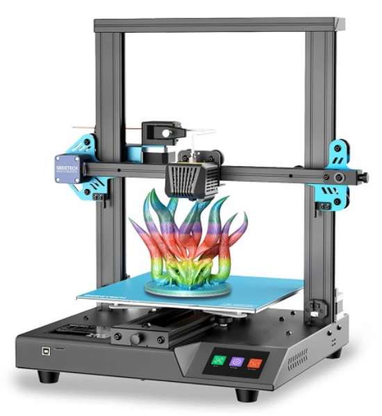
Geeetech Mizar S is a very good 3D printer with a medium print volume on the market. It has many premium features such as the automatic print bed leveling and the flexible print bed, it is also very well suited for beginners.
Mizar S uses a dual gear Bowden extruder, that is lightweight and compact in design, allowing higher speeds and generating less vibration. The extruder of the Mizar S has two drive gears. This gives greater extrusion force and control over the filament than standard Bowden extruders with only one active drive gear.
The print bed of the Geeetech Mizar S doesn’t have any screws with which you can manually change the tilt. Instead, the print bed is mounted stationary and the print head has a built-in sensor that allows it to measure the distance to the print bed.
A dual Z-axis in a 3D printer increases accuracy because there is a stepper motor on each side of the Z-axis to move the X-axis in the Z-direction. This results in a more stable movement in the Z direction, which leads to higher accuracy when printing objects.
Main Specification
Printer Type FDM
Layer Thickness 0.1-0.3 mm
Printing Material PLA,ABS, PETG, Silk PLA, Wood Polymer
Building Platform Volume 255*255*260 mm
Auto-leveling Yes
Break Resuming Yes
Preheat time(110℃) 7 min
Nozzle Diameter 0.4 mm
Positioning Precision X axis: 0.011 mm;Y axis: 0.011 mm;Z axis: 0.0025 mm;
Printing Accuracy ±0.1 mm
Printing Speed 10~150 mm/S; recommend 60~80 mm/s
Display Screen 3.5” Colorful Touch Screen
Operating System Windows, Mac, Linux,
Slicing Software Repetier-Host, EasyPrint Lite, Cura
Supported File Format .gcode
Hotbed Max. Temperature 110 ℃
Extruder Max. Temperature 250 ℃
Environmental Temperature 10-40 ℃
Electrical Parameter
Power Input 115/230 V AC, 50/60 Hz
Power Output DC 24 V-15 A Max, 360 W
Connectivity Interface 1*TF Card, 1*USB cable
Power Supply Unit Certification CE, FCC,ROSH
Mechanical Parameter
Printing Size 255*255*260 mm
Net Weight(kg) 8.9 kg
Gross Weight(kg) 11.2 kg
Printer Whole Size 362(W)*377(L)*653(H)mm
Packing Dimension 522(L)*482(W)*310(H)mm
Watch the unboxing video and user manual before assembling the printer.
Printer Maintenance
How to replace PSU
| Tools necessary for this guide |
|---|
| Allen keys - 2.5/3 mm
Philips screwdriver for PSU cables |
The power supply is available in our website: Mizar S power supply
Watch the video tutorial: How to replace the power supply of the Mizar S
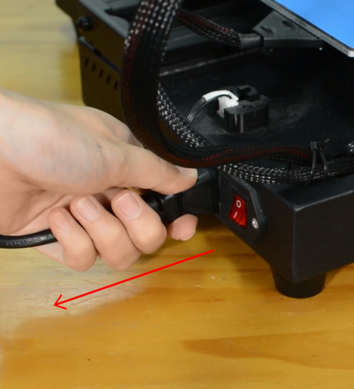
Turn the printer off and unplug it from the socket.
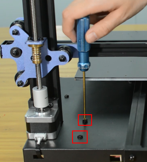
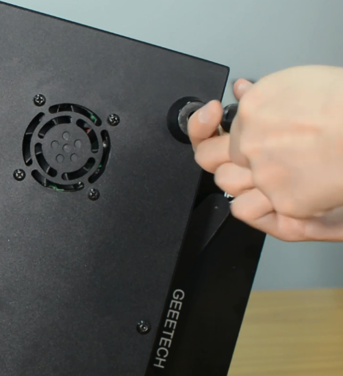
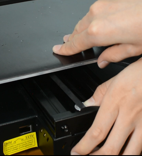
Release and remove the two screws that secure the PSU.
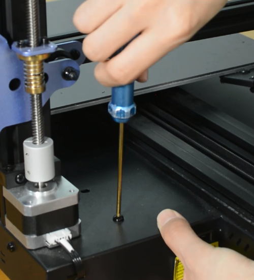
Remove the bottom cover, unplugging the cooling fan.
Using a Philips screwdriver release all five screws.
Release and remove the two screws that holding the PSU and make sure you hold it before releasing the last screw.
Assembling the new PSU.
Ensure that the DIP switch of the power supply is adjusted to the right voltage!
Please triple-check you have connected the cables correctly!
There is a risk of damaging the PSU or the printer itself, if the cables are connected incorrectly or not tightened properly!
Tighten the two screws.
Plug the cooling fan back in and secure the base cover with screws.
How to replace a hotend
Mizar S hotend kit is available in our website: Mizar S hotend kit
Watch video tutorial: How to replace the hotend of Mizar S
| Tools necessary for this guide |
|---|
| Wrench size 10 mm
Allen keys – 1.5/2/2.5/3 mm Flat screwdriver tip width 2.5 mm Diagonal pliers Electrical tape Zip ties Craft knife or equivalent |
Step 1 Preparing
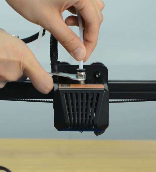
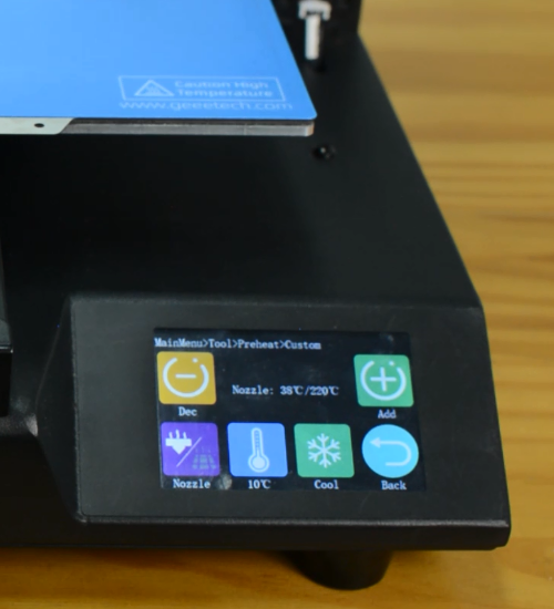
Preheat the nozzle to 220 Celsius from the LCD menu, then unload the filament from the hotend.
Remove the Teflon tube from the hotend.
Before moving to step 2, remember to turn the printer off and unplug it from the socket!
Step 2 Disassembling the hotend
Remove the hotend housing and disconnect the hotend thermistor.
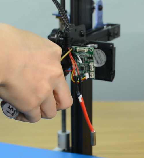
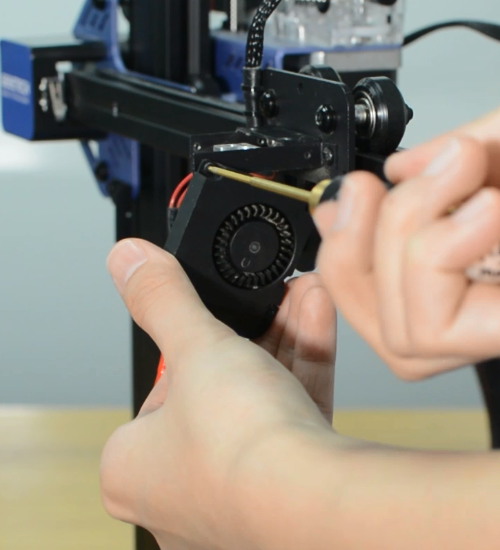
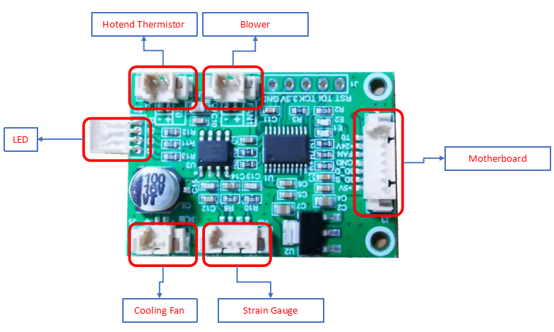
Release and remove the two screws that secure the hotend, then unplug all the cables on the extension board.
Remove the extension board and the part cooling fan.
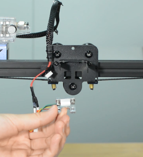
Remove the strain gauge.
Step 3 Disconnecting the hotend cables
Remove the bottom cover and disconnect the cooling fan.
Disconnect the heater cartridge.
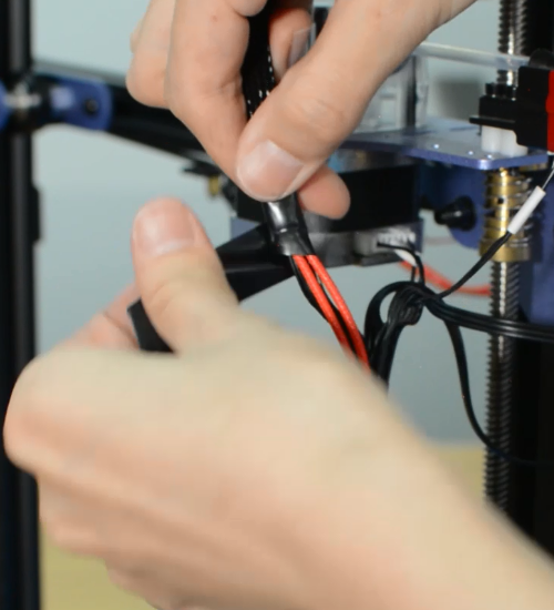
Cut off the heat-shrink tubing from the connection wire. Avoid cutting the cable.
Remove the old heater cartridge.
Step 4 Install the new hotend kit
Fix the new strain gauge.
Install the new hotend.
Run the cables of heater cartridge through the textile sleeve.
Insert the both heater cables into the connector.
Make sure the cables are fully inserted and tightened!
Tighten the textile sleeve with electrical tape.
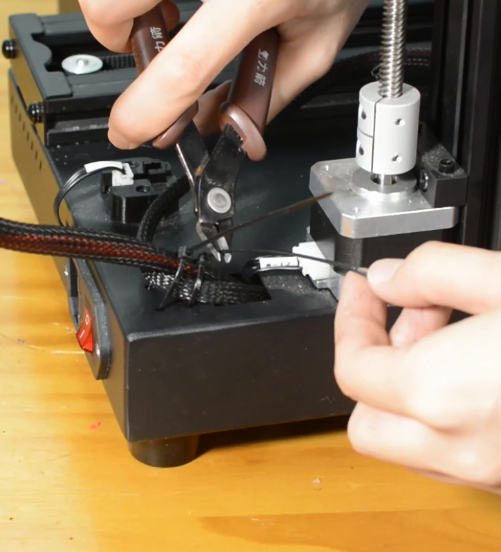
Tighten the zip ties and cut the remaining parts.
Install the part cooling fan and extension board.
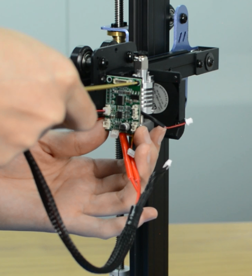
Connect all the hotend cables to the extension board.
Step 5 Install the PTFE tube
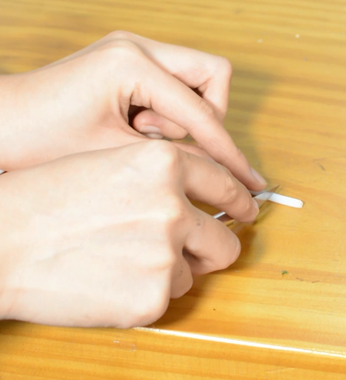
Take the razor or knife and carefully trim the tube. The Teflon ends should remain flat. Uneven ends may cause hotend to jam.
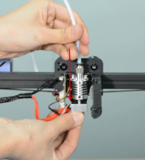
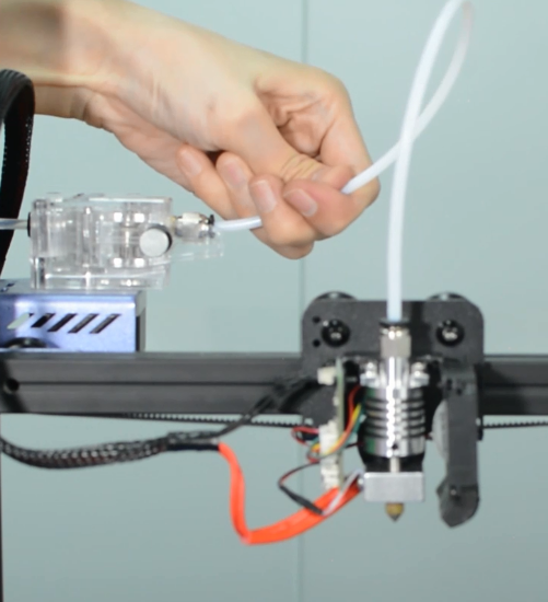
Insert and push the new PTFE tube into the heatbreak all the way down.
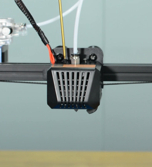
Install the print head housing.
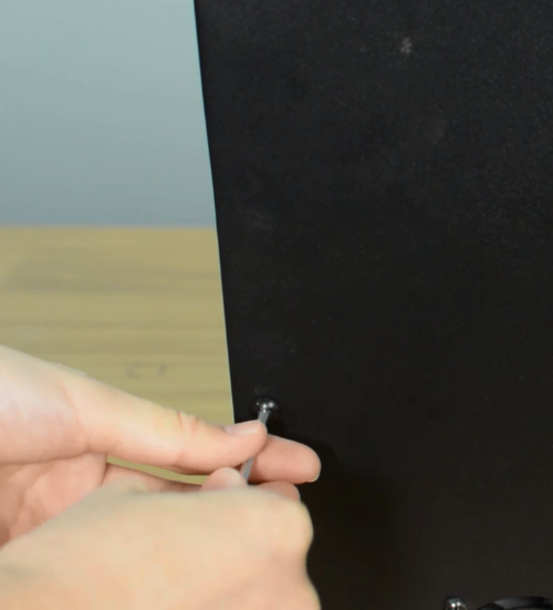
Plug the cooling fan back in and secure the base cover with screws.
It's done! Plug in the printer and turn it on to check whether the printer works properly.
How to replace a hotbed
| Tools necessary for this guide |
|---|
| Allen keys – 3 mm
Flat screwdriver tip width 2.5 mm Diagonal pilers Zip ties |
The hotbed is available in our website: Mizar S hotbed kit
Watch video tutorial: How to replace the hotbed of Mizar S
Turn the printer off and unplug it from the socket!
Remove the bottom cover, unplugging the cooling fan.
Disconnect the hotbed cable and hotbed thermistor.
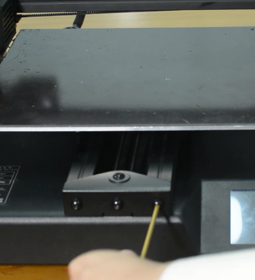
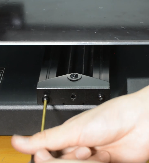
Release and remove the three screws of the Y-axis rail.
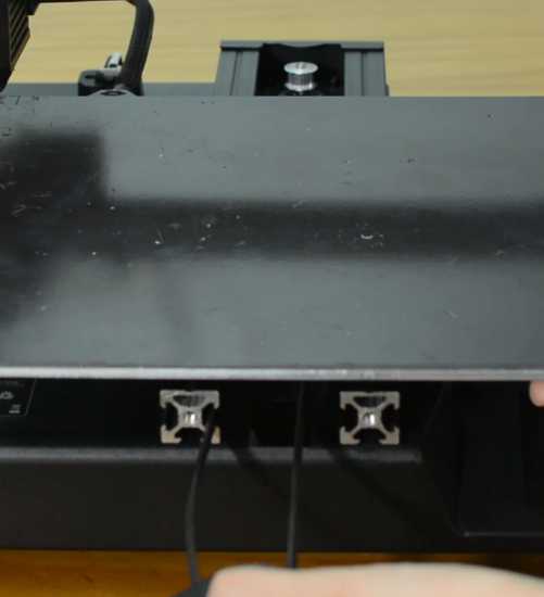
Remove the hotbed from the printer.
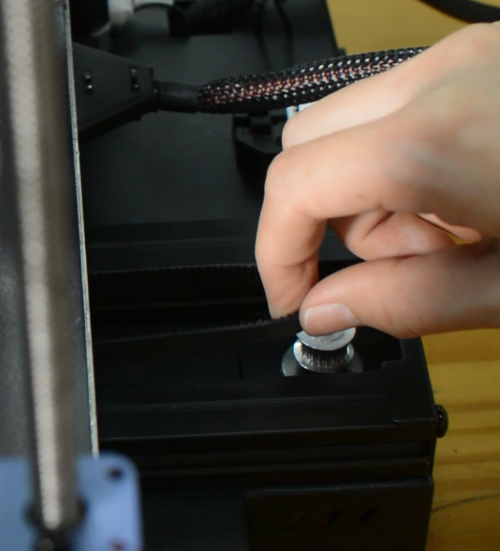
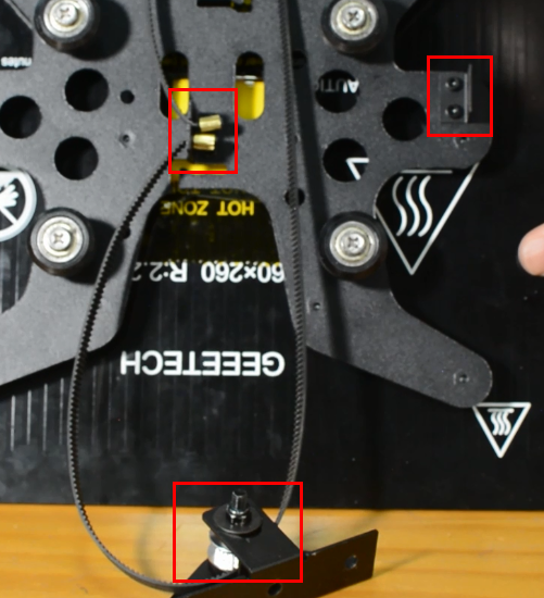
Install the new hotbed kit and pay attention to how the Y-axis belt is installed as the pictures below.
Tighten the three screws.
Connect the hotbed thermistor and hotbed cable.
Plug the cooling fan back in and secure the base cover with screws.
How to replace a screen
| Tools necessary for this guide |
|---|
| Allen keys - 2.5/3 mm |
The screen is available in our website: Mizar S touch screen
Watch video tutorial: How to replace the touch screen of Mizar S
Turn the printer off and unplug the power cable!
Remove the bottom cover, unplugging the cooling fan.
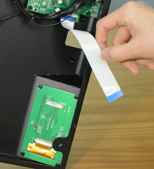
Unplug the screen connector and put it to the side.
Release and remove four screws on screen.
Set the screws in place, tighten the screws.
Connect the LCD cable.
Plug the cooling fan back in and secure the base cover with screws.
How to replace a control board
| Tools necessary for this guide |
|---|
| Allen keys – 2.5/3 mm
Flat screwdriver tip width 2.5 mm |
The control board is available in our website: Mizar S control board
Watch video tutorial: How to replace the control board of Mizar S
Turn the printer off and unplug the power cable!
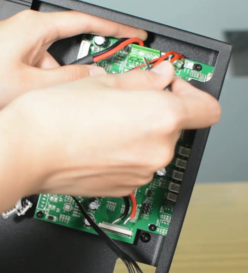
Remove the bottom cover, unplugging the cooling fan.
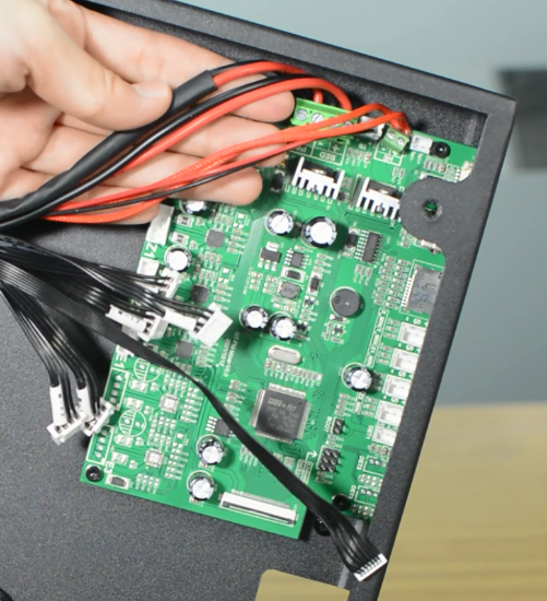
Disconnecting all the cables.
Replace with a new control board and tighten the screws securely.
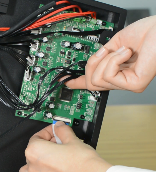
Plug in all the connections as the picture below.
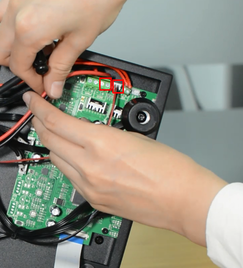
Insert the cables of power supply and hotbed. Red wire is positive and black wire is negative.
Make sure the cables are fully inserted and tightened!
Connect the LCD cable.
Plug the cooling fan back in and secure the base cover with screws.
It's done! Plug in the printer and turn it on to check whether the printer works properly.
How to replace a filament sensor
The filament sensor will be worn out after long time use. We’ve uploaded a filament guide on our website to fix this.
And thanks to the 3D printer community, there’re lots of upgrade mods on the website for reference.
Geeetech Mizar S filament roller guide by by JTProuhet
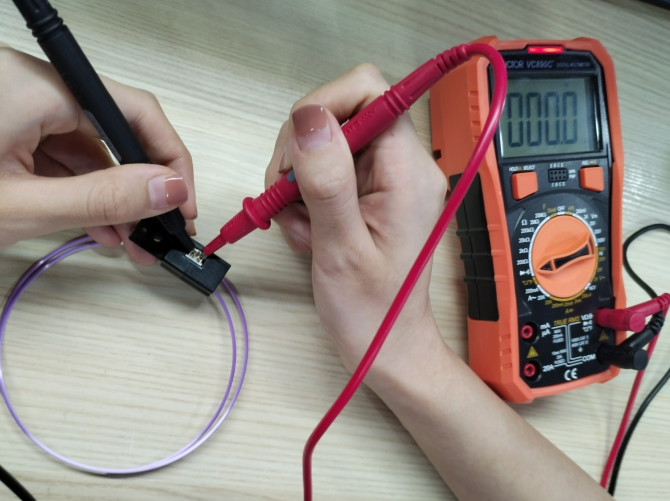
If there’s error on the screen prompts like “Change Filament” even filament has been uploaded, maybe the sensor is broken. You can test it by a multimeter.
Remember load a small piece of filament through the sensor before test. By touching each of the measurement leads of the multimeter to the two pins of the sensor, a signal (beep or 0 value on the multimeter screen) will indicate that the component is intact and therefore, should work.
How to clean the hotend and replace a nozzle
| Tools necessary for this guide |
|---|
| Tweezers for nozzle
Wrench size 6/10/20 mm Cleaner rod (1.5mm diameter, 100mm length) Needle for nozzle Allen key - 2 mm |
The nozzle for Mizar S is available in our website: 5pcs* Nozzle for Mizar S
Watch video tutorial: How to clean hotend and replace nozzle of Mizar S
Step 1 Clean the hotend
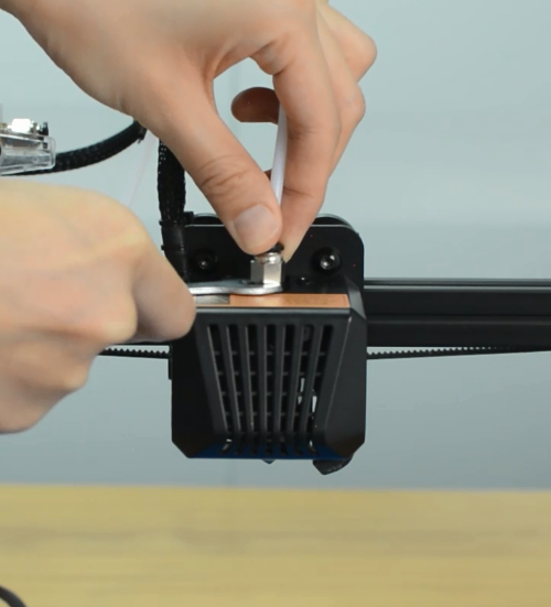
Preheat the nozzle to 220 Celsius from LCD menu.
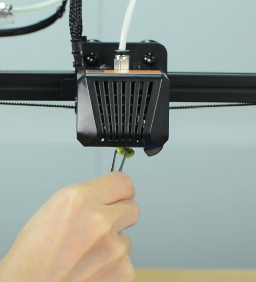
Clean the surface of the nozzle with tweezers.
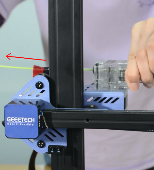
Unload the filament from the hotend.
Remove the Teflon tube from the hotend.
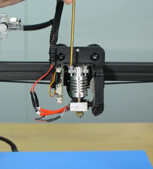
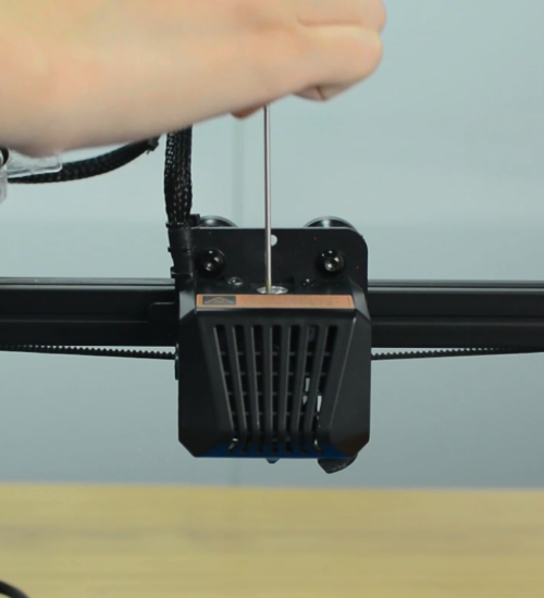
Use a cleaner rod (1.5 mm diameter, 100 mm length) to push it in and out several times, making the clog out. Do not use excessive force.
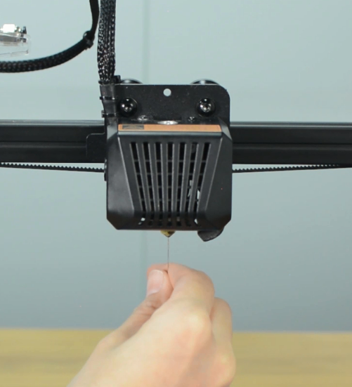
Use a needle to clean the nozzle.
Step 2 Replace a nozzle
Turn the printer off.
Remove the print head housing.
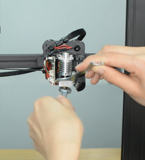
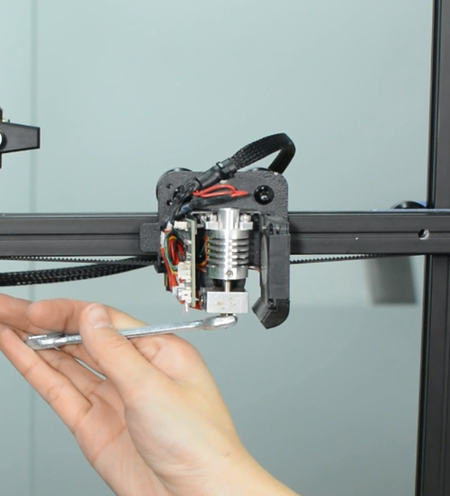
Release the old nozzle with a 6mm spanner while holding the heater block in place with a 20mm spanner.
Install the new nozzle and tighten it gently, but firmly. Do not use excessive force!
Place the silicone sock for heater block.
Install the print head housing.
Insert and push the new PTFE tube into the heatbreak all the way down.
Trouble Shooting
Black screen
Warning: Never install or unplug anything on a printer while it’s being powered!
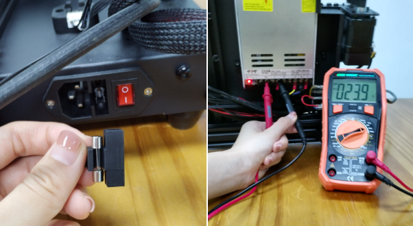
(a)Please check if the power supply is working normally. The red indicator on the switch should be light. And also check the fuse in the little black box, it should be complete without burns. Please measure the output voltage, which should be around 24 Volts.
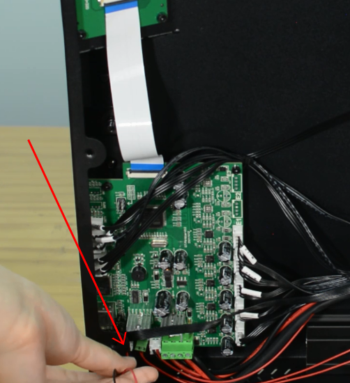
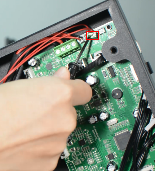
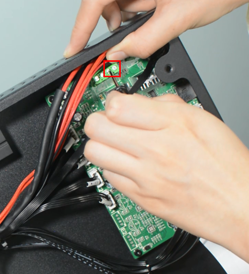
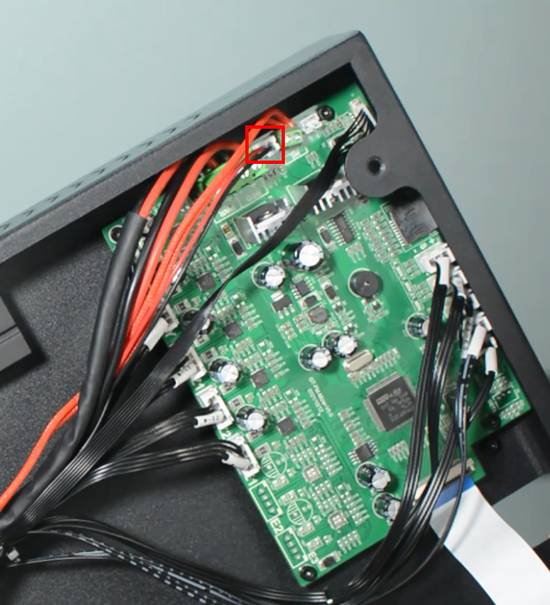
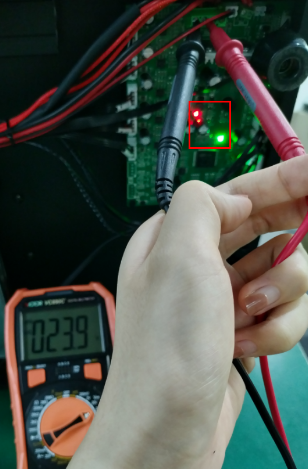
(b)Please check if the control board is working normally. There’re one green LED and one red LED working as the picture shown below. Measure the input voltage of the control board, it should be around 24 Volts.
(c)Make sure the screen is connected properly.
Mintemp Error
The Mintemp error in 3D printers is a design feature within your firmware for safety in regard to temperature. When below a set temperature, the heater will be switched off due to possibly having a broken thermistor wire. It can be observed a negative the temperature on the LCD screen.
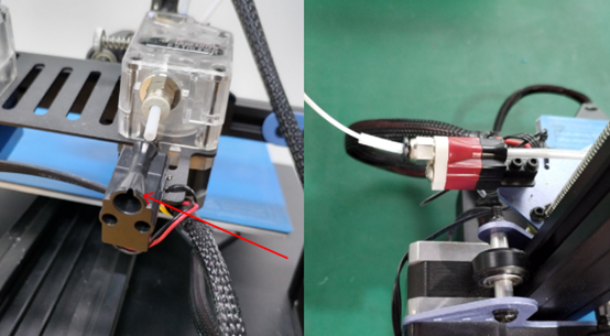
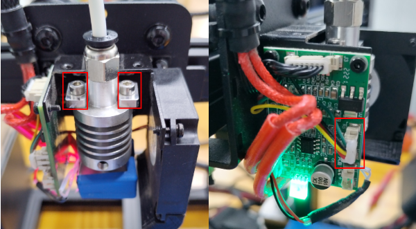
Check if the hot end connector and thermistor are connected properly as the pictures below. Check the hotend cables and thermistor, make sure they’re not broken or burn out.
You can test the thermistor by a multimeter. If it fails to read the resistance, then the wire is broken. At room temperature, it should be 80 kΩ - 125 kΩ. Or apply heat to the thermistor with a heater, blow-dryer or other heating device. The resistance should decline steadily in seconds if it works. If not, replace it.
Another common reason behind getting the MINTEMP error is from being in a cold environment, especially in winter months. Your 3D printer is designed to have a minimum temperature that it can operate in as a safety feature.
Update Firmware
Download the latest firmware in our website
How to update:
1.Put "bin” file and "assets” folder in TF card root directory, insert TF card into the printer.
2.Turn on the printer, the screen will display the firmware upgrade progress bar.
3.After the progress is complete, the printer starts to upgrade UI.
4.Update is complete.
Notice:
1.After the upgrade, delete the bin file and assets folder in the TF card to prevent repeated upgrades.
2.Level the hotbed after the upgrade is complete.
Automatic leveling failed
(a)Nozzle calibration failed
You should use a scraper against the nozzle and gently push up to make the nozzle “feel” the pressure. If this still fails, check if the strain gauge in the hotend is connected properly, and ensure the cables are not broken.
(b)Homing failed
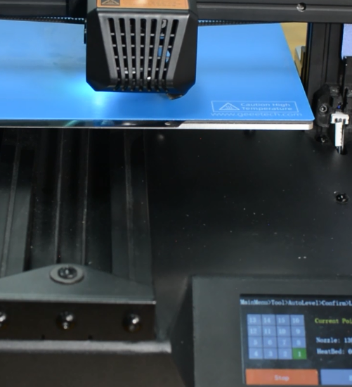
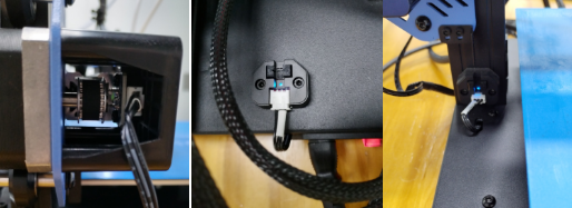
Check the X, Y and Z axes end stops, make sure they’re all connected properly. Note the photoelectric end stops on the Y and Z axes, which normally have a blue signal light. You can home the X, Y and Z axes one by one to check which axis is faulty.
(c)The first layer is messy
Please clean the hotbed before printing, this will help to get a good adhesion. We recommend a thicker first layer, 0.3 mm is good. If these’re not helpful, please try to adjust the Z-offset. What’s more, you can try adjust the hotbed temperature, for example, the Geeetech wood PLA needs a lower hotbed temperature but PETG needs higher. Consumables don't stick to the hot bed
Material break detection wear
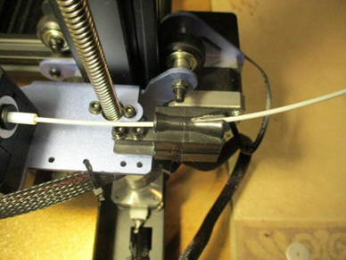
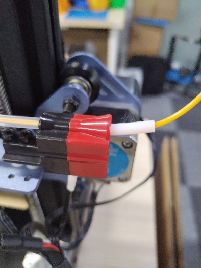
Please add a section of pipe in front of the filament sensor to prevent wearing.
The printer cannot be turned on
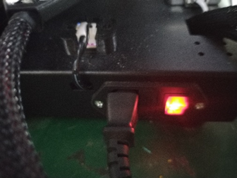
1.Please make sure you select the correct voltage first.
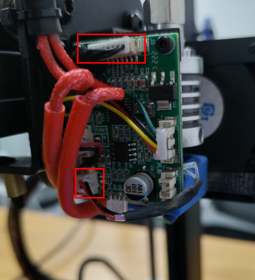
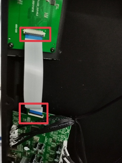
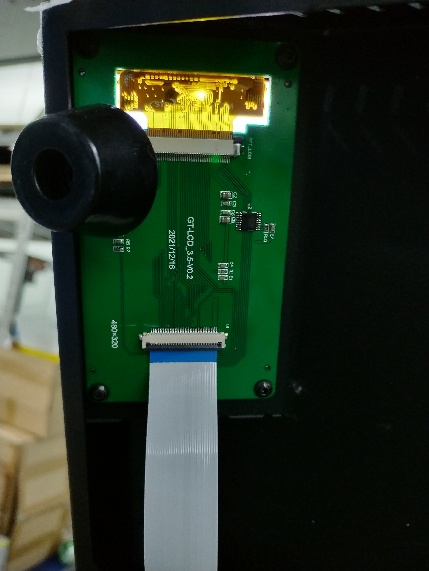
2. Check that the motherboard is properly connected to the screen, as shown in Figure 1. Switch the mains on and the screen works as shown in Figure 2.
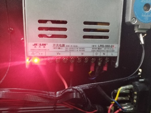
3. The power supply is working normally as shown in Figure 3.
4. Check whether the mainboard works properly, as shown in Figure 4.
The extruder keeps making a click sound
(a)Decrease the print speed. If the print speed is too fast, the extruder will push the filament too quickly. Filament may not have enough time to melt and even clog in the nozzle. A clogged nozzle will then exert pressure back on the extruder, resulting in clicking. For PLA, our recommended print speed is 60mm/s.
(b)Increase the print temperature. If the temperature is too low, it will not melt the filament properly. This can also clog the nozzle. As the extruder is no longer able to push the filament ahead, it starts “slipping”.
(c)Check the pneumatic fittings. A loose coupling could therefore allow molten filament to leak into a gap between the tube and the nozzle. This will restrict the flow of the filament, causing the extruder keep clicking.
(d)Change the extruder gear. After many hours of use, the teeth of the extruder may eventually wear out. Thus, it can no longer hold the filament, leading to filament slipping in the extruder.
(e)A low-tension extruder arm bar. If spring tension is too low, the extruder gear will not properly grip the filament. This leads to filament grinding.
(f)Check if the grub screw on the extruder gear. If the grub screw is loose, the gears will fail to grab the filament when feeding into the hotend.
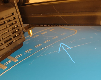
The consumables don't fall off the Mylar
Filament residues stick to Mylar sheets and are difficult to remove, usually because the nozzle is too close to the hot bed when printing the first layer, resulting in very thin extruded filaments. The spring steel sheet is flexible and easy for part removal. But keep in mind that prints are easy to remove after the plate cools down. Don’t try to forcefully remove the object when the sheet is still hot. We do not suggest you use the adhesive on the sheet, because the adhesive is difficult to clean up and may have an opposite effect. If there’re leftover residue on the sheet, preheat the hotbed to 80 degrees to make the plastic soft. Then use the wet cloth wiping the plate and gently scrap the residue off. A dirty bed will cause poor first layer adhesion. You need to remove the dirt, leftover residue or oil from the bed surface. Isopropyl alcohol (IPA) 90%+ will help to degrease the platform.
The consumables don't stick to the hot bed
1.Nozzle is too close to the hotbed
Even though the extruder is working but no filament is depositing on the hotbed, Check if the nozzle is too close to the hotbed. Adjust the Z-offset value slightly will help.
2.Print temperature is too low
Some filament needs more higher temperature, manually feed the filament, if it can not be extruded, please try increase the print temperature.
3.The extruder is not working
Check if the grub screw on the extruder gear. If the grub screw is loose, the gear will fail to grab the filament when feeding into the hotend. Also check if the extruder motor is connected properly.
The thickness of the first layer printed is uneven
The thin area of the first layer is because the nozzle is too close to the hot bed, so that the filament is under extrusion. Please clean up the hot bed and adjust the value of Z-offset. Check out our YouTube channel for more details. It is recommended to set the initial layer height to 0.3mm and the initial layer speed to 20mm/s.
Geeetech Mizar S Z-offset Exquisite Leveling:https://www.youtube.com/watch?v=iuF_-HQl8HI&list=PLODCkot3GrigK0dnpjArzevcaKNLslUgP&index=6
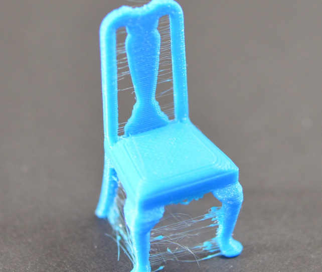
The print is brushed or leaked
The drawing is the residual linear object left when the extruder crosses the open space. The common measure to solve this problem is to control the "withdrawal" function in the slice software. If the tap is opened in the slice, the consumables will be pulled back in the opposite direction for a distance before the sprinkler head is moved to the next point. When the product moves to the next point, the consumables will be squeezed out again. Although theoretically, it can be avoided, there are several problems in practice:
1. Insufficient withdrawal distance The most important setting in the return is the return distance, which determines how much plastic is drawn from the nozzle during the return. Usually, the more plastic the draw from the nozzle, the less obvious the drawing is.
2. The withdrawal speed is too slow Another important setting in the withdrawal is the speed of the withdrawal, which determines how fast the consumables are withdrawn. If the pump rate is too slow, the melted supplies will still flow out of the nozzle. If the withdrawal is too fast, the separation of the unmelted part and the melted part of the consumables may occur, or the extrusion wheel may bite off a piece of the consumables.
3. The temperature is too high If the temperature of the extrusion head is too high, the consumables in the nozzle will become very sticky, and it is easy to flow out of the nozzle, but if the temperature is too low, the consumables are more difficult to squeeze out. In the determination of the drawing distance and drawing speed are more appropriate, there is still a drawing situation, you can try to reduce the temperature of the extrusion head by 5-10 degrees Celsius.
4, the suspended movement distance is too long The suspended distance will also have a great impact on the drawing. The short distance movement, the melted consumables do not have enough time to flow out of the nozzle, but the long distance movement is very easy to produce the phenomenon of drawing. Some slicing software has relevant Settings, which can avoid the long distance movement.
Underextrusion and overextrusion
For most 3D printers, how much material the extruder squee. In the process of printing, due to some problems, the extrusion of the material will be less than expected. This requires the user to carefully look at the printed work to see if there are irregular distances between the textures and, and if so, usually for the following reasons.
1.Material diameter When users buy materials, it is usually recommended to buy formal brand products. When buying inferior products, the diameter of the material may be unequal. For such materials, the diameter can usually be tested with measuring calipers to ensure that the diameter of the material is consistent with the package label.
2.Increase extrusion multiple If the material diameter and identification is maintained, but there is a lack of extrusion material, then the extrusion speed needs to be adjusted. This is a very practical setting for the user, who can directly modify the amount of extrusion to squeeze more material. ABS material usually presses 109%, while PLA is 105%.
3.Reduce extrusion speed If the material is normal and the extrusion is too much, the extrusion is reduced to keep the printing at a normal level.
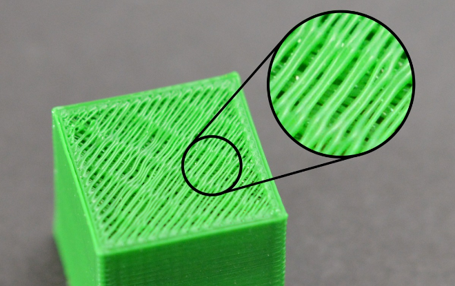
The top-level seal is insufficient
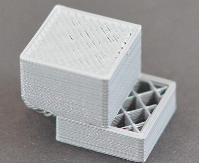
In order to save printing materials, most 3D printers will use different filling methods for the internal space, the commonly used ratio is 20% -30%, that is to say, in the closed product interior, only 20% -30% of the material, in this case, the work can still maintain a certain strength. However, in some of the works, users will find that some of the works are not perfect, and even have holes or gaps. If you encounter this problem, here are a few simple Settings, you can adjust and fix it.
1. Top layers When the number of capped layers is insufficient, it is easy to lead to the phenomenon of material falling, and the number of layers can be increased accordingly;
2. The filling rate is too low Too much reduction of the filling material, will make the internal space is too large, resulting in the number of upper layers can not be effectively supported, it is suggested to increase the internal filling ratio;
3. Insufficient extruding materials of the extruder Due to the lack of extrusion material, the nozzle can not meet the expected requirements, which can be adjusted by adjusting the extrusion amount.
Print offset
Most printers use a stepper motor to drive the machine in motion, meaning that the printer has no function to detect where the print head is located. However, once the stepper motor receives external force interference, or there is a large resistance, it may lead to the printing head dislocation, and the printer does not detect and correct the measures, so that the printed product produces dislocation \ displacement and other conditions.
1. The print head moves too fast If the printing speed or empty speed exceeds the speed the stepper motor can handle, dislocation will occur. Adjust the low walking speed, and lower the acceleration if necessary.
2. Mechanical or electronic reasons If the above does not solve your problem, then you need to check the mechanical and electronic aspects, most machines use belt drive, over time, the belt may lengthen and become loose, thus causing the belt to slip from the pulley. The solution is also relatively simple, the belt drive mechanism will generally have to adjust the tension degree of the belt mechanism, the belt adjustment is more tight some can be solved. However, it should be noted that if the adjustment is too tight, it will form a huge resistance between the rotating shaft and the bearing or may be unable to rotate. So the degree of tightness needs to be moderate. Another mechanical problem is the machine meter screw (top wire), this small screw is used to fix the pulley on the stepping motor shaft, so that the pulley rotates with the motor shaft, but if the screw is loose, there will be shaft rotation and the wheel will not turn. This situation also causes the problem of layer offset. The electronic problem may be that the stepper motor power supply current is insufficient, resulting in the stepper motor is not enough force to overcome the resistance. It may also be that the stepper motor drives the chip to overheating, causing the stepper motor to stop turning before the chip is cooled. There are many other points in electronics.
Surface spots and stripes problems
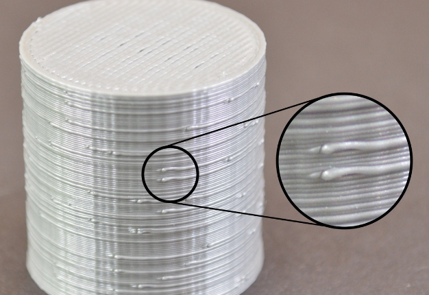
In the process of 3D printing, the extruder frequently extracts, most of the extruder can maintain a good extrusion width in the movement, however, in each withdrawal and extrusion process, there will be additional vibration. For example, if you look closely at the outer surface of the printed object, you may be able to see very small traces, the place where the printing begins. 3D printing starts at certain locations on the outer edge, and eventually goes back to the starting place. The trace is usually represented by surface spots or stripes; several ways to improve the problem:
1. Return extraction and slide wipe setting If you find such traces on the surface of the printed piece, you can first observe the printing process at the beginning of each layer? Or do they appear after each layer is printed? If it appears before starting printing, the value of "restart additional extrusion distance" in the slicing software should be modified to be negative; if the withdrawal distance is 1.00mm and the additional extrusion distance is-0.2mm, the withdrawal is 1.00mm, but only 0.8mm. This should improve the problem of developing traces before starting printing. If this appear after the end of each layer, you need to adjust another setting called "taxi wipe", which causes the extruder to stop extrusion near the end, release the pressure, and the taxiway end point. This value was adjusted until the trace disappeared. In general, this value is set to 0.2-0.5mm.
2. Avoid unnecessary withdrawal In general, in the slicing software, there will be the option of "withdrawing only when crossing the open area". After this option is opened, the 3D printer will not turn on the withdrawal when crossing the internal space of the object. This can reduce the occurrence of traces, in addition to the bowden extruder, and the extruder far from the nozzle, close the back may perform better;
3. Non-fixed point backwithdrawal The conventional withdrawal will pause during the withdrawal, which is not suitable for the extruder with high internal pressure during bowden printing. Some slicing software can set the "wipe nozzle" option, which will cause the printer to continue to move during the withdrawal. In general, the wipe distance is set to 5mm;
4. Set the printing start point All slicing software provides the option to print the starting point, which can start printing at a location specified by the user. For example, in a building, you can set the starting point on the back side of it, so that when printing, these traces will be arranged on the back side of the building, and these points are not visible on the front side.
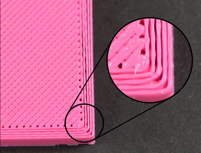
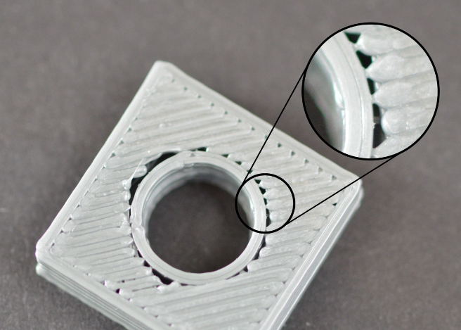
There are gaps between the edge and the filling
1. Insufficient edge overlap (overlap) Edge overlap refers to how much the fill overlaps with the internal edge. If you have 20%, try to 30% or more
2. Printing speed is too fast Usually, the fill is much faster than the edges. Too fast filling speed, will let the filling and edge are not enough time to combine. If you change the overlap and the problem isn't solved, try to reduce the printing speed to 50%. If the problem is solved, you can slowly increase the speed until you find the most suitable printing speed for your printer.
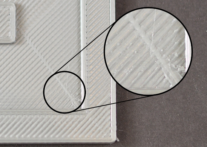
Rough edges and corners
This problem is mainly caused by the heat dissipation is not fast enough. After the high temperature supplies are extruded from the nozzle, they will change their shape in the process of slow cooling. If this problem occurs in the very beginning of the printing, you can refer to the "first layer off-platform problem" mentioned earlier
Top layer surface scratch problem
1. Too much plastic extrusion Encounter the problem of scratches, the first thing to check is, is too much consumables extrusion. If the supplies are squeezed out, each layer is thicker than the set size, which means the scratches form when the nozzle moves through. The solution to this problem can refer to the aforementioned "more consumables"
2. Vertical lifting If you are sure your consumables quantity is correct, but still scratch problems, so you can open in slice software "vertical lift" option, this option will make the machine in back, print head up a certain distance, and then move to the next coordinates, then move down back to the original height, continue to print. It's important to note that the print head will be raised vertically only in places where there is a tap. If you want to make sure that each pass has a vertical lift, make sure that the "draw only when crossing open space" and "minimum distance" options are closed.
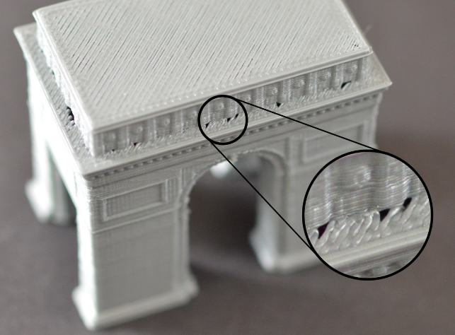
Holare holes in the bottom of the corner linet
This problem often occurs in the situation where the upper level is smaller than the lower level. The following provides several possible causes and solutions to this problem: 1. Insufficient number of edges You can try increasing the number of edges by two; 2. The number of top layers is insufficient You can try to add the top layers by two layers; 3. The filling ratio is too low You can try to increase the fill ratio by 20%.
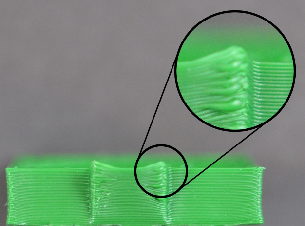
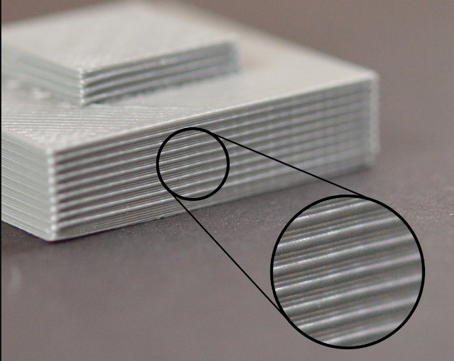
The side edges are uneven
The side of a printed piece is like a thousand-layer cake. In all normal cases, the side of the printed object should look like a smooth surface. Instead of showing the obvious edges, the following are several possible causes and suggested solutions:
1. The extrusion volume is inconsistent Usually this reason is because the tolerance control of the mass line diameter of consumables is not strict. If the line diameter change of your consumables is about 5%, then the extrusion volume change of consumables is as much as 0.05mm. Of course, there are some other possibilities for the inconsistent extrusion quantity, which will be explained in detail in the following "inconsistent extrusion quantity"
2. Temperature change Most 3D printers use PID to control the printing temperature. If the PID setting is not good, the printing temperature will fluctuate up and down (when the temperature rises, the liquidity of consumables is better than when the temperature is low), and the printing temperature fluctuation will affect the extrusion volume. Then, the problem of uneven side edge is generated. A fixed PID control can maintain the printing temperature within 2℃ up and down. If this range is exceeded, the PID needs to be rearranged.
3. Mechanical reasons If you can be sure it's not either, it's probably mechanical. For example, when printing, the printing platform shaking and vibration may lead to the position change of the nozzle, which will lead to inconsistent layer thickness, and thus produce the problem of uneven side edges. Another example: mechanical position or motor differential control problem. Even the small offset of the printing platform can affect each layer of the printed object.
How to print TPU
Nozzle temperature: 220-230℃ Bed temperature: 30-60℃ Print speed: 30-40mm/s Initial print speed: 20mm/s Retraction: Disabled
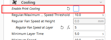
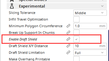
How to print ABS
Nozzle temperature: 230-250℃ Bed temperature: 90-110℃ Print speed: 50-60mm/s Initial print speed: 20mm/s Number of slower layers: 5-10 (The first few layers are printed slower that the rest of the model, to get better adhesion to the build plate.)
Fan speed: 0%
Build plate adhesion: Brim Raft shield: Enable
Build plate adhesion: Brim Raft shield: Enable
How to print PETG
Nozzle temperature: 220-250℃ Bed temperature: 70-80℃ Print speed: 40-50mm/s Initial print speed: 20mm/s Travel speed: 120mm/s
Retraction distance: 6mm for Bowden setups, 2-3mm for direct drive setups Retraction speed: 25-45mm/s Fan speed: 30% Initial fan speed: 0% Build plate adhesion: Brim The recommended parameters are slightly different for different brands of filaments. We can provide you with test models. PETG is hygroscopic. Try using a container or resealable bags.
