Difference between revisions of "Geeetech Thunder 3D printer"
(→FAQ) |
(→Printer Maintenance) |
||
| (93 intermediate revisions by the same user not shown) | |||
| Line 3: | Line 3: | ||
Thunder is a high speed FDM 3D printer with a printing speed of up to 300mm/s. After two years of research and development and testing by GEEETECH engineers, it has achieved high speed printing while ensuring excellent printing quality. It is an excellent 3D printer that can save a lot of precious time for 3D printing enthusiasts. | Thunder is a high speed FDM 3D printer with a printing speed of up to 300mm/s. After two years of research and development and testing by GEEETECH engineers, it has achieved high speed printing while ensuring excellent printing quality. It is an excellent 3D printer that can save a lot of precious time for 3D printing enthusiasts. | ||
| − | [[File: | + | [[File:Thundernew.jpg]] |
| − | |||
| − | |||
•Technology: FDM | •Technology: FDM | ||
| Line 36: | Line 34: | ||
•Printing lighting: Thunder designed a white LED light on the hotend, convenient for checking the nozzle and model condition | •Printing lighting: Thunder designed a white LED light on the hotend, convenient for checking the nozzle and model condition | ||
| − | |||
| − | |||
| − | |||
[[File:Thunderpara.jpg]] | [[File:Thunderpara.jpg]] | ||
| − | |||
| − | |||
•Please read this document carefully to ensure that you understand each installation step, which will improve the efficiency of your assembly and reduce errors; | •Please read this document carefully to ensure that you understand each installation step, which will improve the efficiency of your assembly and reduce errors; | ||
| Line 60: | Line 53: | ||
•Before using the 3D printer, please level the hot bed first. Thunder is equipped with 3D-Touch automatic leveling accessory. Please install the 3D-Touch before leveling the hot bed.You can also use manual hot-bed leveling if you do not have 3D-Touch installed. | •Before using the 3D printer, please level the hot bed first. Thunder is equipped with 3D-Touch automatic leveling accessory. Please install the 3D-Touch before leveling the hot bed.You can also use manual hot-bed leveling if you do not have 3D-Touch installed. | ||
| − | = | + | =Printer Maintenance= |
| + | |||
| + | === '''How to clean the hotend''' === | ||
| + | |||
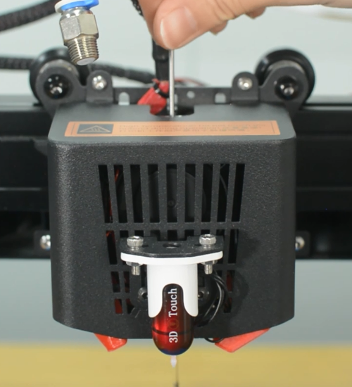
| + | '''1.''' Heat up the nozzle to 200 ℃, then remove the PTFE tube. | ||
| + | |||
| + | [[File:T2.png]] | ||
| + | |||
| + | '''2.''' Use another piece of PLA filament to push through from the top to try to force the stuck filament in the nozzle out. | ||
| + | |||
| + | [[File:T3.png]] | ||
| + | |||
| + | '''3.''' If you find that the hotend is still blocked, then you maybe able to use a small metal rod to push it in and out several times, making the clogging out. Do not use excessive force. | ||
| + | |||
| + | [[File:T4.png]] | ||
| + | |||
| + | === '''How to replace the nozzle''' === | ||
| + | |||
| + | The nozzle is available in our website: [https://www.geeetech.com/10-pcs-nozzles-for-thunder-3d-printer-2-pcs-02mm-nozzles-4-pcs-04mm-nozzles-2-pcs-06mm-nozzles-2-pcs-08-mm-nozzles-p-1404.html 10 Pcs Nozzles for Thunder 3D Printer] | ||
| + | |||
| + | '''1.''' Turn the printer off and unplug the power cable. | ||
| + | |||
| + | [[File:T5.png]] | ||
| + | |||
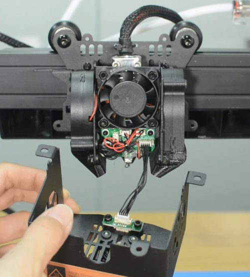
| + | '''2.''' Remove the hotend housing, and one of the blower fans and its bracket. | ||
| + | |||
| + | [[File:T6.png]] | ||
| + | |||
| + | '''3.''' Disconnect the cables of hotend cooling fan and the two blower fans. | ||
| + | |||
| + | '''4.''' Unscrew the extension board and put it aside. | ||
| + | |||
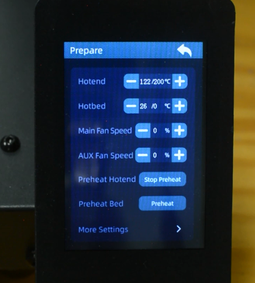
| + | '''5.''' Turn the printer on and preheat hotend. | ||
| + | |||
| + | [[File:T7.png]] | ||
| + | |||
| + | '''6.''' Wear gloves to prevent burns. Place the socket wrench vertically to unscrew the nozzle. Otherwise it is easy to misalign the screw and thread, causing the breakage of the nozzle in the heat block. | ||
| − | Thunder printing | + | [[File:T8.png]] |
| + | |||
| + | '''7.''' Place the socket wrench vertically to install the new nozzle. Do not use excessive force. | ||
| + | |||
| + | [[File:T9.png]] | ||
| + | |||
| + | '''8.''' Place back all the pieces to reassemble the print head. It is done! | ||
| + | |||
| + | === '''How to replace the heat block kit''' === | ||
| + | |||
| + | The heater cartridge and hotend thermistor are available in our website: [https://www.geeetech.com/thunder-hotend-to-motherboard-link-cable-kit-p-1425.html Thunder heater cartridge] [https://www.geeetech.com/1pcs-100kohm-ntc-thermistors-for-thunder-hotend-p-1424.html Thunder thermistor] [https://www.geeetech.com/thunder-3d-printer-hotend-p-1423.html Thunder heat block kit] | ||
| + | |||
| + | '''1.''' Disassemble the printhead partially. | ||
| + | |||
| + | * a.Turn the printer off and remove the PTFE tube. | ||
| + | |||
| + | [[File:T2.png]] | ||
| + | |||
| + | * b.Remove the hotend housing. Unplug all the cables from the extension board. | ||
| + | |||
| + | * c.Disassemble the extension board and the blower fan. | ||
| + | |||
| + | [[File:T10.png]] | ||
| + | |||
| + | [[File:T11.png]] | ||
| + | |||
| + | '''2.''' Remove the heat block kit. | ||
| + | |||
| + | * a.Release and remove the two screws that secure the heat block. | ||
| + | |||
| + | [[File:T12.png]] | ||
| + | |||
| + | * b.Release the grub screw and remove the heat block. | ||
| + | |||
| + | [[File:T13.png]] | ||
| + | |||
| + | [[File:T14.png]] | ||
| + | |||
| + | * c.Cut off the zip ties and be aware of not cutting the cables. | ||
| + | |||
| + | [[File:T16.png]] | ||
| + | |||
| + | [[File:T17.png]] | ||
| + | |||
| + | * d.Release the screw terminals for heater cartridge and remove the cables. Unplug the cables of hotend and the hotend fan. | ||
| + | |||
| + | [[File:T18.png]] | ||
| + | |||
| + | [[File:T19.png]] | ||
| + | |||
| + | * e.Remove the heat block kit completely from the printer and put it aside. | ||
| + | |||
| + | |||
| + | '''3.''' Install the new heat block kit. | ||
| + | |||
| + | * a.Install the new heat block to the below of the heat sink and tighten it by the two screws. | ||
| + | |||
| + | [[File:T20.png]] | ||
| + | |||
| + | [[File:T21.png]] | ||
| + | |||
| + | [[File:T22.png]] | ||
| + | |||
| + | * b.Tighten the grub screw to secure the heatbreak. | ||
| + | |||
| + | [[File:T23.png]] | ||
| + | |||
| + | * c.Place back all the pieces to reassemble the print head. Use zip ties to manage the cables. | ||
| + | |||
| + | * d.Place back all the pieces to reassemble the print head. Make sure the cables are fully inserted and tightened! | ||
| + | |||
| + | * e.Connect the cables for hotend fan and hotend. | ||
| + | |||
| + | [[File:T24.png]] | ||
| + | |||
| + | [[File:T25.png]] | ||
| + | |||
| + | * '''Warning :''' Tie the wires properly, otherwise it will scratch the model during printing, leading the wires disconnected. | ||
| + | |||
| + | [[File:T26.png]] | ||
| + | |||
| + | [[File:T27.png]] | ||
| + | |||
| + | '''4.''' It's done. Heat up the printer and try it out. | ||
| + | |||
| + | === '''How to replace the hotend''' === | ||
| + | |||
| + | The hotend is available in our website: [https://www.geeetech.com/thunder-hotend-kit-with-link-cable-p-1426.html Thunder hotend] | ||
| + | |||
| + | '''Prepare:''' Turn the printer off and unplug the power cable from the socket. | ||
| + | |||
| + | '''1.''' Disassemble the hotend kit | ||
| + | |||
| + | * a.Remove the PTFE tube and the hotend housing and disassemble the hotend fan. | ||
| + | |||
| + | [[File:T28.png]] | ||
| + | |||
| + | * b.Release and remove the two screws that secure the hotend. | ||
| + | |||
| + | [[File:T29.png]] | ||
| + | |||
| + | * c.Cut off the zip ties and be aware of not cutting the cables. | ||
| + | |||
| + | [[File:T30.png]] | ||
| + | |||
| + | [[File:T17.png]] | ||
| + | |||
| + | * d.Release the screw terminals for heater cartridge and remove the cables. | ||
| + | |||
| + | [[File:T18.png]] | ||
| + | |||
| + | * Unplug the cables of hotend and the hotend fan. | ||
| + | |||
| + | [[File:T19.png]] | ||
| + | |||
| + | '''2.''' Install the new hotend kit | ||
| + | |||
| + | * a.Install the new hotend to the bracket. | ||
| + | |||
| + | [[File:T32.png]] | ||
| + | |||
| + | * b.Connect all the cables for hotend. Install the hotend housing. | ||
| + | |||
| + | * c.Connect the cables of hotend fan and hotend. | ||
| + | |||
| + | * d.Insert the both heater cables into the connector and tighten the screw terminals. Make sure the cables are fully inserted and tightened! | ||
| + | |||
| + | [[File:T25.png]] | ||
| + | |||
| + | '''3.''' It's done. Heat up the printer and try it out. | ||
| + | |||
| + | === '''How to replace the power supply''' === | ||
| + | |||
| + | === '''How to auto leveling''' === | ||
| + | |||
| + | === '''How to manual leveling''' === | ||
| − | + | =Trouble Shooting= | |
| + | === '''How to upgarde UI''' === | ||
| − | + | A TF card or USB flash drive is required to upgrade the UI of Thunder. See following steps: | |
| + | Step 1: Copy the "System" folder to TF card or USB drive root menu. | ||
| − | |||
| − | [ | + | [[File:Thunder17.jpg]] |
| − | + | Step 2: Insert the TF card or USB drive into Thunder, and then power on. At this time, you will see that the display screen is updating the UI. This process takes a long time, please wait patiently. | |
| − | " | + | Step 3: When it prompts "Update succeeded", please remove the TF Card/ U-Disk and restart the printer. UI upgrade is complete. |
| − | + | Note: After UI upgrading, delete the "System" folder on the TF card or USB flash drive to avoid repeated UI upgrade during power-on. | |
| + | === '''How to upgarde firmware''' === | ||
| − | + | Thunder does not support TF card upgrading firmware directly. You need to use Smartto Kits to upgrade the firmware through the USB cable. The steps are as follows: | |
| + | |||
| + | 1.Install the CH340 driver (the TF card attached has the driver file, or you can search and download the CH340 driver from the Internet). | ||
| + | |||
| + | 2.Plug the B-type interface of the USB cable into the printer and the other end into your computer. | ||
| + | |||
| + | 3.Install Smartto Kits, then open Smartto Kits, select "Quick Start", then select "Update" to go to the firmware upgrade page. | ||
| + | 4.Click the "Disconnected" button in the upper right corner. The Setting sidebar is displayed in left side. Select the serial port for Thunder, set the serial port baud rate to 115200, and click "Connect" to Connect Thunder. | ||
| − | |||
| − | + | [[File:Thunder12.jpg]] | |
| − | + | 5.Click the blank space in the Update page and select the firmware you want to upgrade. | |
| + | [[File:Thunder13.jpg]] | ||
| − | |||
| − | " | + | 6.Click "Update" to start upgrading the firmware. |
| − | |||
| + | [[File:Thunder14.jpg]] | ||
| − | |||
| + | [[File:Thunder15.jpg]] | ||
| − | |||
| − | + | 7.When it prompts "Update Succeeded", firmware upgrade completes. | |
| − | [[File: | + | [[File:Thunder16.jpg]] |
| − | |||
| + | === '''How to use Smarttokits''' === | ||
[https://www.geeetech.com/download.html?version_id=514 Smatto Kits] | [https://www.geeetech.com/download.html?version_id=514 Smatto Kits] | ||
| Line 129: | Line 300: | ||
| − | [[File: | + | [[File:Thunderusb.jpg]] |
| Line 251: | Line 422: | ||
On this page, users can send command directly. | On this page, users can send command directly. | ||
| − | |||
| − | Thunder | + | === '''How to print with Cura''' === |
| + | |||
| + | Thunder printing speed can reach 300mm/s. In order to ensure the printing quality even in high speed, the correct setting of slicing parameters is essential. We recommend the Cura slicing software and provide Thunder configuration file for Cura slicing software on this page. | ||
| + | |||
| + | Cura slicing software download link: https://github.com/Ultimaker/Cura | ||
| + | |||
| + | |||
| + | We offered 2 configuration files for Thunder, see below about importing file to Cura software. | ||
| + | |||
| + | |||
| + | [https://www.geeetech.com/download.html?version_id=522 Thunder Cura 4.x Configuration] | ||
| + | |||
| + | [https://www.geeetech.com/download.html?version_id=523 Thunder Cura 5.0&5.1 Configuration] | ||
| + | |||
| + | |||
| + | For Cura 4.x version, the import path for the two configuration files is: | ||
| + | |||
| + | "geeetech_Thunder.def.json" put into | ||
| + | |||
| + | C:\Program Files\Ultimaker Cura 4.x\resources\definitions | ||
| + | |||
| + | |||
| + | [[File:Thunderconfig1.jpg]] | ||
| + | |||
| + | |||
| + | "geeetech_Thunder_extruder.def" put into | ||
| + | |||
| + | C:\Program Files\Ultimaker Cura 4.13.1\resources\extruders | ||
| + | |||
| + | |||
| + | [[File:Thunderconfig2.jpg]] | ||
| + | |||
| + | |||
| + | Copy file folder “geeetech” to Ultimaker Cura 4.13.1\resources\\quality | ||
| + | |||
| + | Copy the seven son files of variants folder to Ultimaker Cura 4.13.1\resources\\variants | ||
| + | |||
| + | |||
| + | For the Cura 5.x version, the import path for the two configuration files is: | ||
| + | |||
| + | "geeetech_Thunder.def.json" put into | ||
| + | |||
| + | C:\Program Files\Ultimaker Cura 5.1.0\share\cura\resources\definitions | ||
| + | |||
| + | |||
| + | [[File:Thunderconfig3.jpg]] | ||
| + | |||
| + | |||
| + | "geeetech_Thunder_extruder.def" put into | ||
| + | |||
| + | C:\Program Files\Ultimaker Cura 5.1.0\share\cura\resources\extruders | ||
| + | |||
| + | |||
| + | [[File:Thunderconfig4.jpg]] | ||
| + | |||
| + | |||
| + | Copy file folder “geeetech” to Ultimaker Cura 5.X\share\cura\resources\quality | ||
| + | |||
| + | Copy the seven son files of variants folder to Ultimaker Cura 5.X\share\cura\resources\variants | ||
| + | |||
| + | |||
| + | == '''Turn the printer on but the screen is black''' == | ||
| + | |||
| + | <big>Warning: Never install or unplug anything on a printer while it’s being powered!</big> | ||
| + | |||
| + | |||
| + | (a)Check if the power supply is working normally. The red indicator on the switch should be light. And also check the fuse in the little black box, it should be complete without burns. Please measure the output voltage, which should be around 24 Volts. | ||
| + | |||
| + | [[File:W41.png]] | ||
| + | |||
| + | (b)Check if the control board is working normally. There’re two green LEDs and one red LED working as the picture shown below. Measure the input voltage of the control board, it should be around 24 Volts. | ||
| + | |||
| + | [[File:W42.png]] | ||
| − | + | (c)Make sure the screen is connected properly. | |
| − | + | == '''The extruder keeps making a click sound''' == | |
| − | + | (a)Decrease the print speed. If the print speed is too fast, the extruder will push the filament too quickly. Filament may not have enough time to melt and even clog in the nozzle. A clogged nozzle will then exert pressure back on the extruder, resulting in clicking. For PLA, our recommended print speed is under 250 mm/s. | |
| − | |||
| + | (b)Increase the print temperature. If the temperature is too low, it will not melt the filament properly. This can also clog the nozzle. As the extruder is no longer able to push the filament ahead, it starts “slipping”. | ||
| − | |||
| + | (c)Check the pneumatic fittings. A loose coupling could therefore allow molten filament to leak into a gap between the tube and the nozzle. This will restrict the flow of the filament, causing the extruder keep clicking. | ||
| − | + | [[File:W43.png]] | |
| + | (d)Change the extruder gear. After many hours of use, the teeth of the extruder may eventually wear out. Thus, it can no longer hold the filament, leading to filament slipping in the extruder. | ||
| − | |||
| + | (e)A low-tension extruder arm bar. If spring tension is too low, the extruder gear will not properly grip the filament. This leads to filament grinding. | ||
| − | |||
| + | (f)Check if the grub screw on the extruder gear. If the grub screw is loose, the gears will fail to grab the filament. | ||
| − | [[File: | + | [[File:W35.png]] |
| + | == '''Nothing is printing''' == | ||
| − | + | (a)Nozzle is too close to the hotbed | |
| + | Even though the extruder is working but no filament is depositing on the hotbed, Check if the nozzle is too close to the hotbed. Adjust the Z-offset value slightly will help. | ||
| − | |||
| + | (b)Print temperature is too low | ||
| − | + | Some filament needs more higher temperature, manually feed the filament, if it can not be extruded, please try increase the print temperature. | |
| − | |||
| − | + | (c)The extruder is not working | |
| − | + | Check if the grub screw on the extruder gear. If the grub screw is loose, the gears will fail to grab the filament when feeding into the hotend. Also check if the extruder motor is connected properly. | |
| − | |||
| + | == '''Mintemp error''' == | ||
| − | + | The Mintemp error in 3D printers is a design feature within your firmware for safety in regard to temperature. When below a set temperature, the heater will be switched off due to possibly having a broken thermistor wire. It can be observed a negative the temperature on the LCD screen. | |
| − | |||
| − | + | Check if the hot end connector and thermistor are connected properly as the pictures below. Check the hotend cables and thermistor, make sure they’re not broken or burn out. | |
| − | + | [[File:W44.png]] | |
| − | + | You can test the thermistor by a multimeter. If it fails to read the resistance, then the wire is broken. At room temperature, it should be 80 kΩ - 125 kΩ. | |
| + | Or apply heat to the thermistor with a heater, blow-dryer or other heating device. | ||
| − | + | The resistance should decline steadily in seconds if it works. If not, replace it. | |
| − | + | Another common reason behind getting the MINTEMP error is from being in a cold environment, especially in winter months. Your 3D printer is designed to have a minimum temperature that it can operate in as a safety feature. | |
| − | = | + | == '''Automatic leveling failed''' == |
| − | + | (a)3D Touch is abnormal | |
| + | Check if the 3D Touch cables are connected properly. You can use the “Test” function to check if the 3D Touch is working normally. | ||
| − | + | [[File:W45.png]] | |
| + | (b)Homing failed | ||
| − | + | Check the X, Y and Z axes end stops, make sure they’re all connected properly. Note the photoelectric end stops on the Y and Z axes, which normally have a blue signal light. You can home the X, Y and Z axes one by one to check which axis is faulty. | |
| − | + | [[File:W46.png]] | |
| − | + | Also check the X and Y axes closed loop motor connections. | |
| − | + | [[File:W50.png]] | |
| − | + | (c)The first layer is messy | |
| − | + | Please clean the hotbed before printing, this will help to get a good adhesion. We recommend a thicker first layer, 0.3 mm is good. If these’re not helpful, please try to adjust the Z-offset. What’s more, you can try adjust the hotbed temperature, for example, the Geeetech wood PLA needs a lower hotbed temperature but PETG needs higher. | |
| − | + | == '''Spring steel sheet problem''' == | |
| − | + | The spring steel sheet is flexible and easy for part removal. But keep in mind that prints are easy to remove after the plate cools down. Don’t try to forcefully remove the object when the sheet is still hot. We do not suggest you use the adhesive on the sheet, because the adhesive is difficult to clean up and may have an opposite effect. | |
| − | + | If there’re leftover residue on the sheet, preheat the hotbed to 80 degrees to make the plastic soft. Then use the wet cloth wiping the plate and gently scrap the residue off. | |
| − | + | A dirty bed will cause poor first layer adhesion. You need to remove the dirt, leftover residue or oil from the bed surface. Isopropyl alcohol (IPA) 90%+ will help to degrease the platform. | |
| − | |||
| − | + | == '''Filament sensor''' == | |
| − | + | If there’s error on the screen prompts like “Change Filament” even filament has been uploaded, maybe the sensor is broken. You can test it by a multimeter. | |
| − | + | Remember load a small piece of filament through the sensor before test. By touching each of the measurement leads of the multimeter to the two pins of the sensor, a signal (beep or 0 value on the multimeter screen) will indicate that the component is intact and therefore, should work. | |
| + | [[File:W1.png]] | ||
| − | '''Nozzle discharge abnormality''' | + | =='''Nozzle discharge abnormality'''== |
1. Filament is knotted and stuck, and the feeding is not smooth. | 1. Filament is knotted and stuck, and the feeding is not smooth. | ||
| Line 365: | Line 611: | ||
| − | '''The extruder gear slips and makes abnormal noise''' | + | =='''The extruder gear slips and makes abnormal noise'''== |
1. Nozzle blocking, refer to the "nozzle discharge abnormality" treatment. | 1. Nozzle blocking, refer to the "nozzle discharge abnormality" treatment. | ||
| Line 372: | Line 618: | ||
| − | '''First layer abnormal''' | + | =='''First layer abnormal'''== |
1. The first layer does not stick: the nozzle is too far away from the hot bed, please adjust the hotbed leveling again. | 1. The first layer does not stick: the nozzle is too far away from the hot bed, please adjust the hotbed leveling again. | ||
| Line 379: | Line 625: | ||
| − | '''Layer shift''' | + | =='''Layer shift'''== |
1. The printing speed of model slices is too fast, please reduce the printing speed. | 1. The printing speed of model slices is too fast, please reduce the printing speed. | ||
| Line 388: | Line 634: | ||
| − | '''X/Y axis Closed-loop Control Abnormality''' | + | =='''X/Y axis Closed-loop Control Abnormality'''== |
During the using of THUNDER, if the X-axis or Y-axis is stuck in the process of movement, it may be caused by the following two reasons after excluding the non-pulley structure and improper connection of wiring: | During the using of THUNDER, if the X-axis or Y-axis is stuck in the process of movement, it may be caused by the following two reasons after excluding the non-pulley structure and improper connection of wiring: | ||
| Line 396: | Line 642: | ||
2.The magnet of the closed-loop control unit of the X-axis motor or Y-axis motor is loose or falls off. The magnet needs to be fixed on the motor shaft with glue again. | 2.The magnet of the closed-loop control unit of the X-axis motor or Y-axis motor is loose or falls off. The magnet needs to be fixed on the motor shaft with glue again. | ||
| − | [[File: | + | [[File:Thunder20.png]] [[File:Thunder19.png]] |
| − | '''Filament''' | + | =='''Filament'=='' |
Does Thunder require high-speed PLA filament to achieve high-speed printing? | Does Thunder require high-speed PLA filament to achieve high-speed printing? | ||
| − | No, Thunder is designed to achieve high-speed printing with ordinary PLA filaments, so Thunder can achieve high-speed printing with ordinary PLA filaments.. | + | No, Thunder is designed to achieve high-speed printing with ordinary PLA filaments, so Thunder can achieve high-speed printing with ordinary PLA filaments. |
| + | |||
| + | |||
| + | =='''G-code for part cooling fan and auxiliary part cooling fan'''== | ||
| + | |||
| + | Part Cooling Fan: | ||
| + | |||
| + | M106 P0 S383 ; ON MainFan 150% | ||
| + | |||
| + | M106 P0 S255 ; ON MainFan 100% | ||
| + | |||
| + | M106 P0 S128 ; ON MainFan 50% | ||
| + | |||
| + | |||
| + | Auxiliary Part Cooling Fan: | ||
| + | |||
| + | M106 P1 S255 ; ON Aux Fan 100% | ||
| + | |||
| + | M106 P1 S128 ; ON Aux Fan 50% | ||
| + | |||
| + | M106 P1 S0 ; OFF Aux Fan | ||
| + | |||
| + | == '''HS-PLA Series Filament "Speed-Temperature" Parameter Settings for Reference''' == | ||
| + | |||
| + | HS-PLA is Geeetech's latest high-speed printing filament. By adjusting the melting point, melting index, glass transition temperature of raw materials and optimizing the production process, Geeetech enables HS-PLA to have stronger fluidity, smoother discharge, faster curing and forming speed and is not easy to deform under the melting condition. Compared with ordinary PLA, HS-pla has the advantages of faster printing speed, higher printing quality and more delicate model surface, which can better meet the high performance requirements of high-speed 3D printers for filament. | ||
| + | |||
| + | |||
| + | Due to the differences in slicing parameters, environment and printers, the following table is for reference only. | ||
| + | |||
| + | |||
| + | [[File:QQ图片20220915154759.png]] | ||
| + | |||
| + | |||
| + | [https://www.geeetech.com/download.html?version_id=521 HS-PLA Series Filament "Speed-Temperature" Parameter Settings for Reference] | ||
| + | |||
| + | == '''X/Y Axis Closed-loop Motor Calibration and Abnormality Elimination''' == | ||
| + | [[File:Thunder 018.jpg]] | ||
| + | |||
| + | |||
| + | X and Y axis motor are all closed-loop controlled, and the closed-loop control sensors on the motors have been calibrated before delivery. Do not remove the closed-loop control sensor if the X-axis and Y-axis are not abnormal. Otherwise it will cause the calibration parameters of the closed-loop control sensor on the X-axis and Y-axis to be offset, resulting in the X-axis or Y-axis stuttering or abnormal jitter during the printing process. | ||
| + | |||
| + | |||
| + | On the screen menu, we provide the X-axis and Y-axis closed-loop control sensor calibration function. The specific path is "Operate" → "Motion". In the "Motion" menu, you can see two buttons "X Encoder Cal" and "Y Encoder Cal". They are X-axis and Y-axis closed-loop control sensor calibration buttons respectively. The specific calibration methods are as follows: | ||
| + | |||
| + | X axis: First, ensure that the hot end can move smoothly on the X axis, and then move the hot end to the middle of the X axis. Then click the "X Encoder Cal" button, and the control panel will pop up to prompt whether to confirm the calibration of the X axis closed-loop control sensor. Choose "YES", and the hot end will move first to the right and then to the left. When the hot end stops, the calibration is complete, and the UI will prompt that the calibration is complete. | ||
| + | |||
| + | Y axis: First, ensure that the hot bed can move smoothly on the Y-axis. Then, move the hot bed to the middle position of the Y-axis, and then click "Y Encoder Cal" button. The control panel will pop up to prompt whether to confirm the calibration of the Y-axis closed-loop control sensor. When the hot end stops, the calibration is complete, and the UI will prompt that the calibration is complete. | ||
Latest revision as of 09:47, 22 July 2023
Contents
- 1 Introduction
- 2 Printer Maintenance
- 3 Trouble Shooting
- 3.1 How to upgarde UI
- 3.2 How to upgarde firmware
- 3.3 How to use Smarttokits
- 3.4 How to print with Cura
- 3.5 Turn the printer on but the screen is black
- 3.6 The extruder keeps making a click sound
- 3.7 Nothing is printing
- 3.8 Mintemp error
- 3.9 Automatic leveling failed
- 3.10 Spring steel sheet problem
- 3.11 Filament sensor
- 3.12 Nozzle discharge abnormality
- 3.13 The extruder gear slips and makes abnormal noise
- 3.14 First layer abnormal
- 3.15 Layer shift
- 3.16 X/Y axis Closed-loop Control Abnormality
- 3.17 G-code for part cooling fan and auxiliary part cooling fan
- 3.18 HS-PLA Series Filament "Speed-Temperature" Parameter Settings for Reference
- 3.19 X/Y Axis Closed-loop Motor Calibration and Abnormality Elimination
Introduction
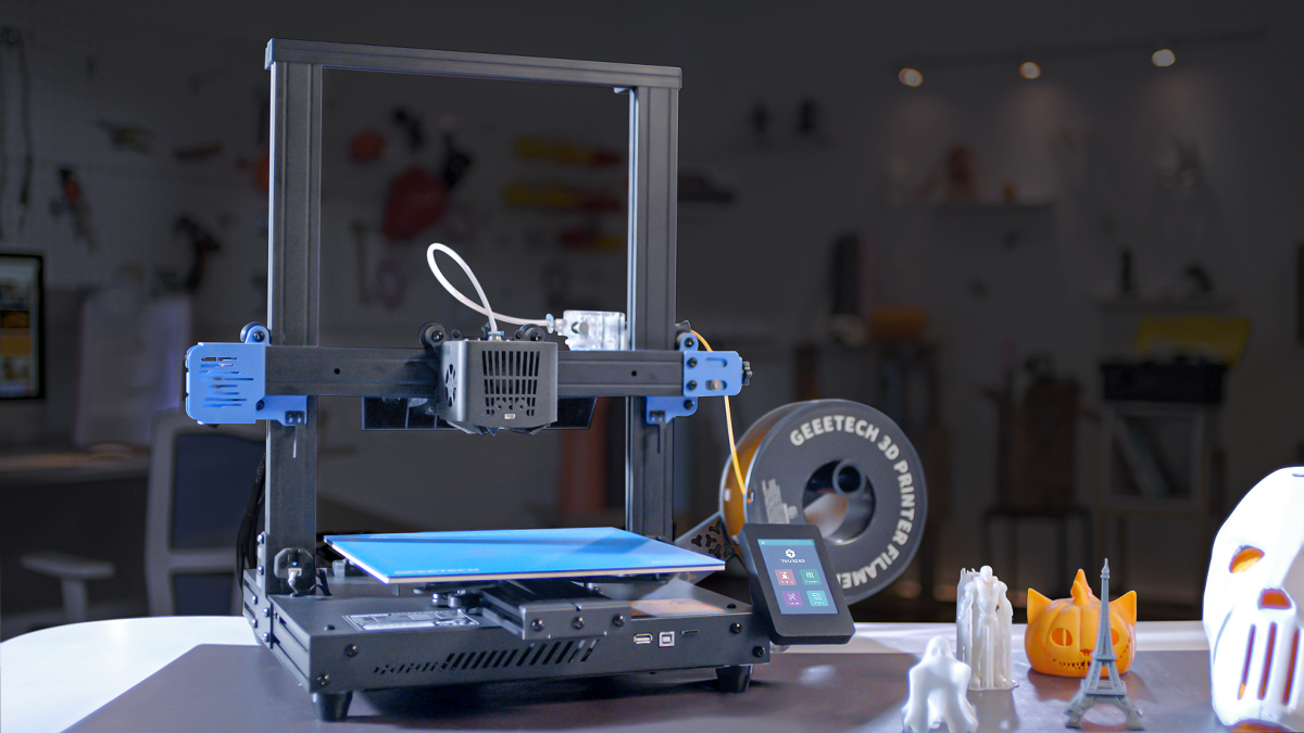
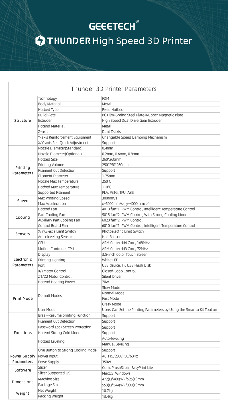
Thunder is a high speed FDM 3D printer with a printing speed of up to 300mm/s. After two years of research and development and testing by GEEETECH engineers, it has achieved high speed printing while ensuring excellent printing quality. It is an excellent 3D printer that can save a lot of precious time for 3D printing enthusiasts.
•Technology: FDM
•High speed printing, speed up to 300mm/s
•All metal body, stable and reliable structure
•Fixed hotbed, no more frequent leveling
•High speed dual gear drive extruder, excellent performance,stand wear and tear
•Motor control: X/Y axis adopts closed-loop drive control,Z axis adopts TMC2208 drive
•Dual Z-axis
•Strong cooling hotend fan: 4010*1, Part Cooling Fan: 5015*2, Auxiliary Part Cooling Fan: 6020*2
•Leveling: support manual leveling and auto-leveing
•Filament broken detection: standard packed with filament broken detection sensor
•Screen password protection: During the printing process, the screen is locked with a password to prevent the printing failure caused by the accidental change of printing parameters
•One button to strong cooling: one button to completely open the hot end fan and auxiliary part cooling fan
•Multi printing modes: Thunder inserted 4 printing modes for different speed level printing, meanwhile, it has a User Mode for users to customize printing parameters
•Break-resuming capability
•Printing lighting: Thunder designed a white LED light on the hotend, convenient for checking the nozzle and model condition
•Please read this document carefully to ensure that you understand each installation step, which will improve the efficiency of your assembly and reduce errors;
•Before starting the power supply, ensure that the voltage range of the power supply is consistent with the local voltage used by the user to prevent power damage;
•Please place the printer in a spacious, flat and ventilated environment. If you do not use the machine for a long time, please pay attention to waterproof and moisture-proof protection for the printer;
•Do not touch any moving parts while the printer is running to avoid personal injury;
•Do not touch the nozzle and hot bed when the printer is working, so as not to cause burns;
•When using the touch screen in the printing process, please pay attention to the movement of the hot bed to prevent the hot bed from hitting your fingers;
•Please use the printer in the environment of 10~40℃, otherwise the printing will be adversely affected;
•Before using the 3D printer, please level the hot bed first. Thunder is equipped with 3D-Touch automatic leveling accessory. Please install the 3D-Touch before leveling the hot bed.You can also use manual hot-bed leveling if you do not have 3D-Touch installed.
Printer Maintenance
How to clean the hotend
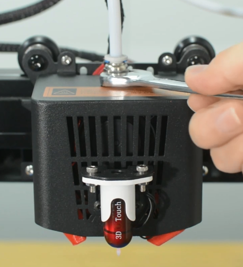
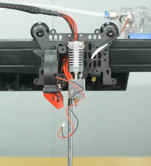
1. Heat up the nozzle to 200 ℃, then remove the PTFE tube.
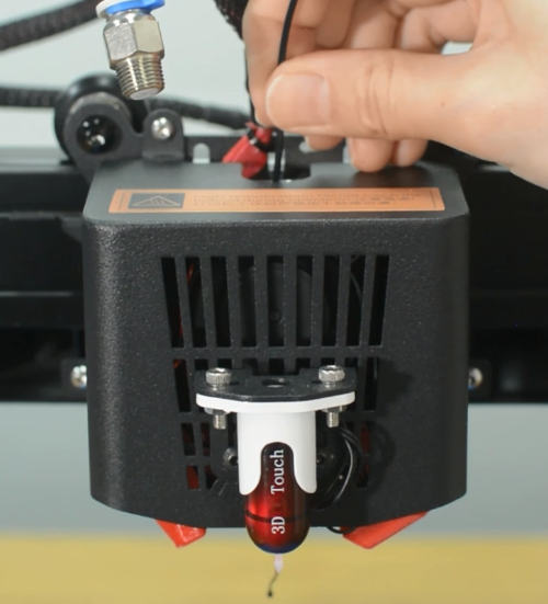
2. Use another piece of PLA filament to push through from the top to try to force the stuck filament in the nozzle out.
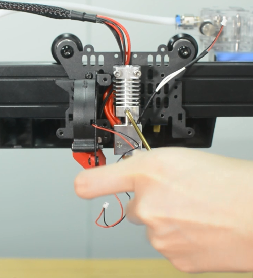
3. If you find that the hotend is still blocked, then you maybe able to use a small metal rod to push it in and out several times, making the clogging out. Do not use excessive force.
How to replace the nozzle
The nozzle is available in our website: 10 Pcs Nozzles for Thunder 3D Printer
1. Turn the printer off and unplug the power cable.
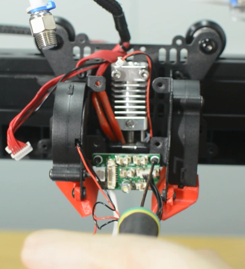
2. Remove the hotend housing, and one of the blower fans and its bracket.
3. Disconnect the cables of hotend cooling fan and the two blower fans.
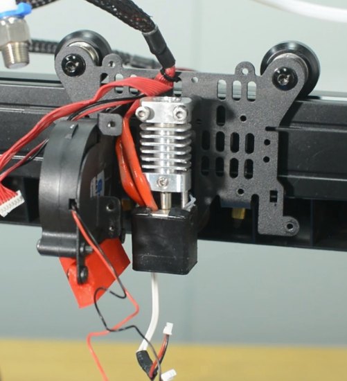
4. Unscrew the extension board and put it aside.
5. Turn the printer on and preheat hotend.
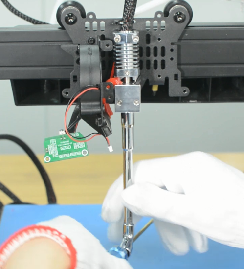
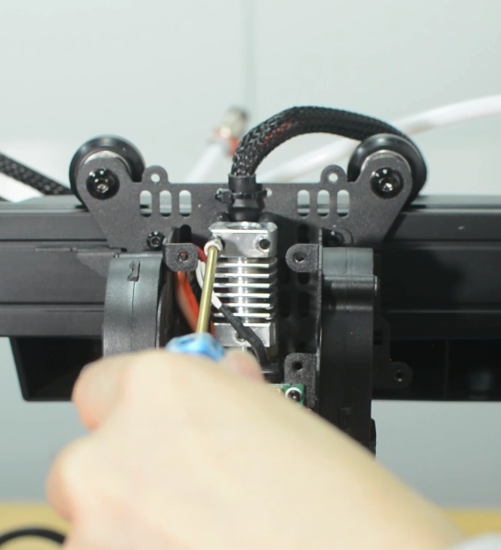
6. Wear gloves to prevent burns. Place the socket wrench vertically to unscrew the nozzle. Otherwise it is easy to misalign the screw and thread, causing the breakage of the nozzle in the heat block.
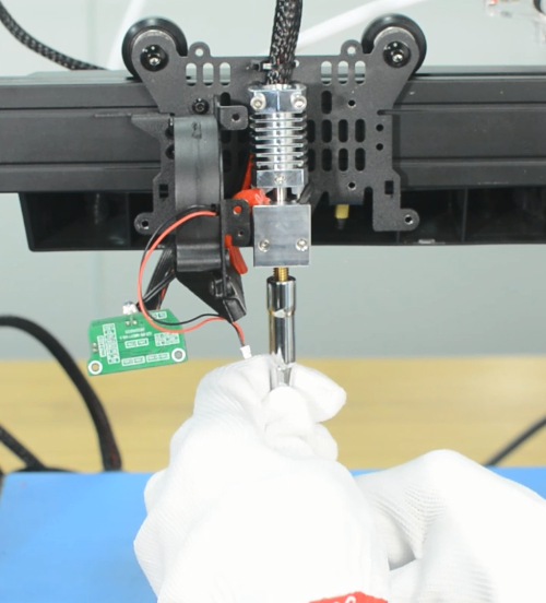
7. Place the socket wrench vertically to install the new nozzle. Do not use excessive force.
8. Place back all the pieces to reassemble the print head. It is done!
How to replace the heat block kit
The heater cartridge and hotend thermistor are available in our website: Thunder heater cartridge Thunder thermistor Thunder heat block kit
1. Disassemble the printhead partially.
- a.Turn the printer off and remove the PTFE tube.
- b.Remove the hotend housing. Unplug all the cables from the extension board.
- c.Disassemble the extension board and the blower fan.
2. Remove the heat block kit.
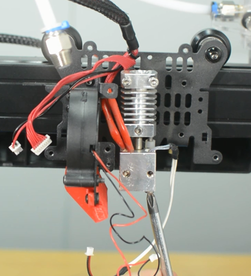
- a.Release and remove the two screws that secure the heat block.
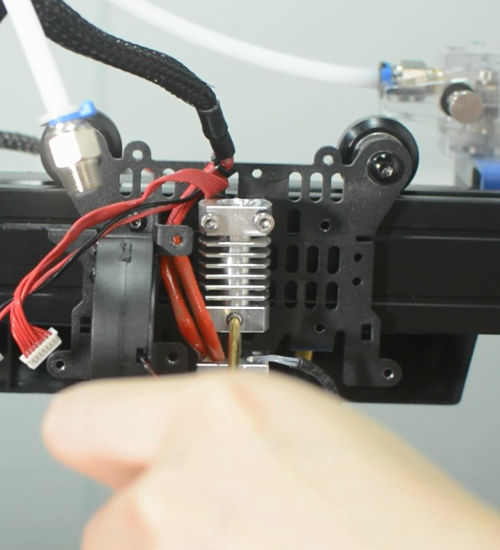
- b.Release the grub screw and remove the heat block.
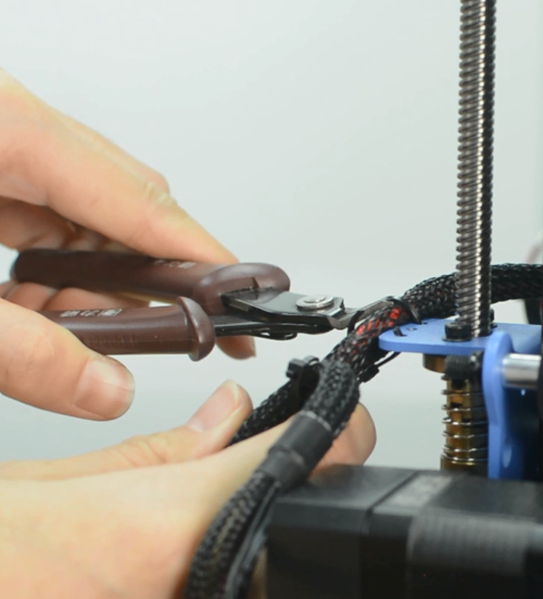
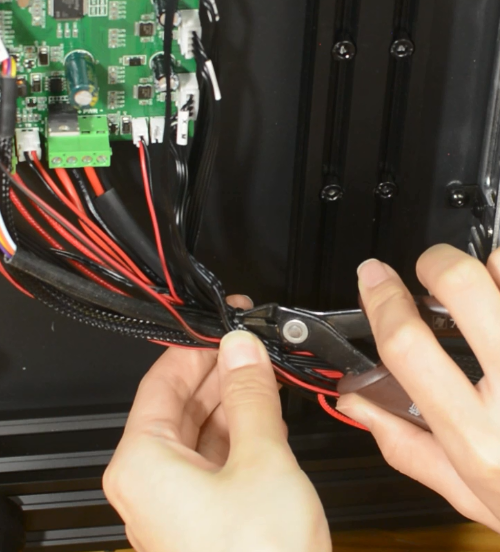
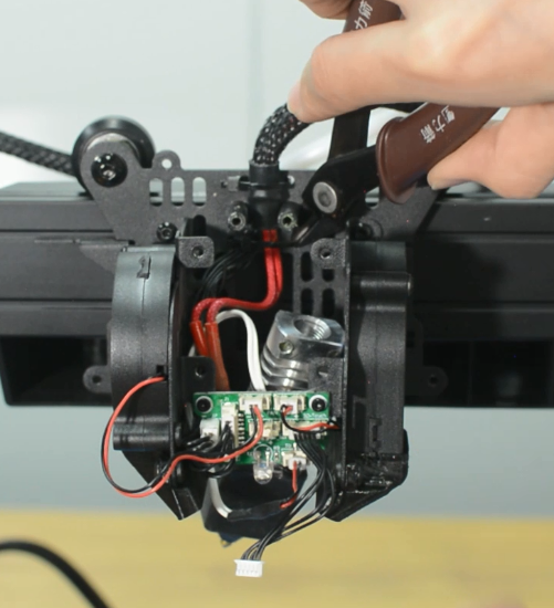
- c.Cut off the zip ties and be aware of not cutting the cables.
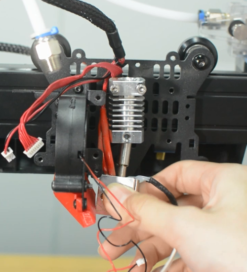
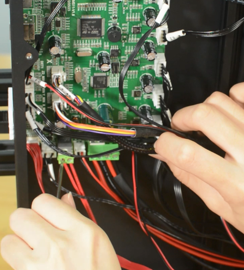
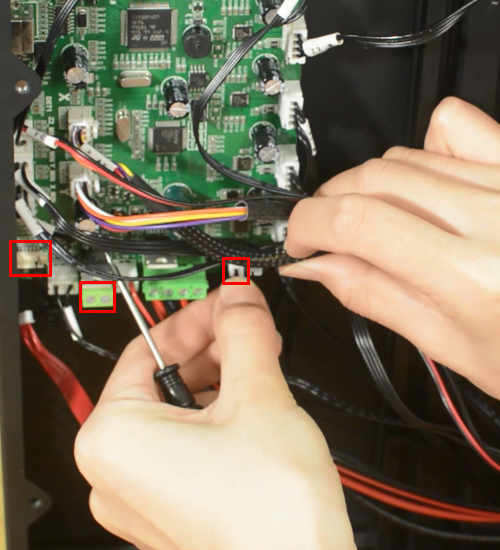
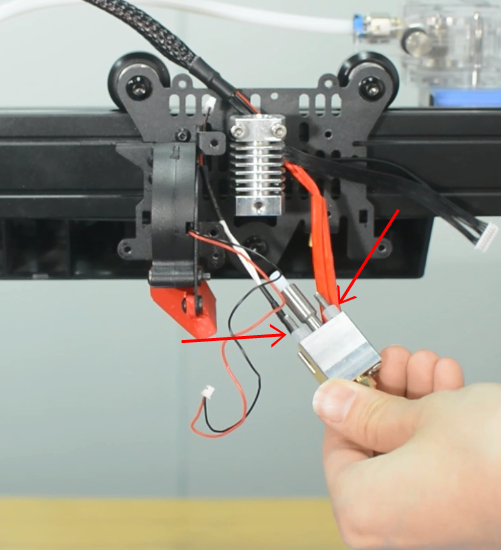
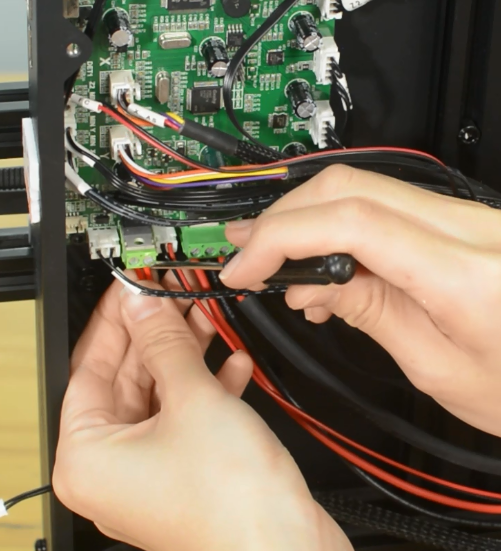
- d.Release the screw terminals for heater cartridge and remove the cables. Unplug the cables of hotend and the hotend fan.
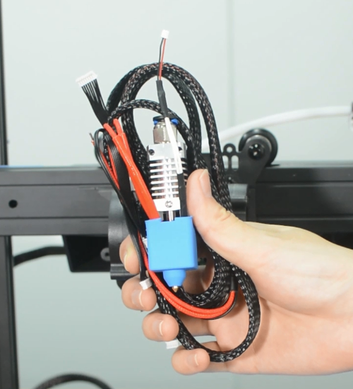
- e.Remove the heat block kit completely from the printer and put it aside.
3. Install the new heat block kit.
- a.Install the new heat block to the below of the heat sink and tighten it by the two screws.
- b.Tighten the grub screw to secure the heatbreak.
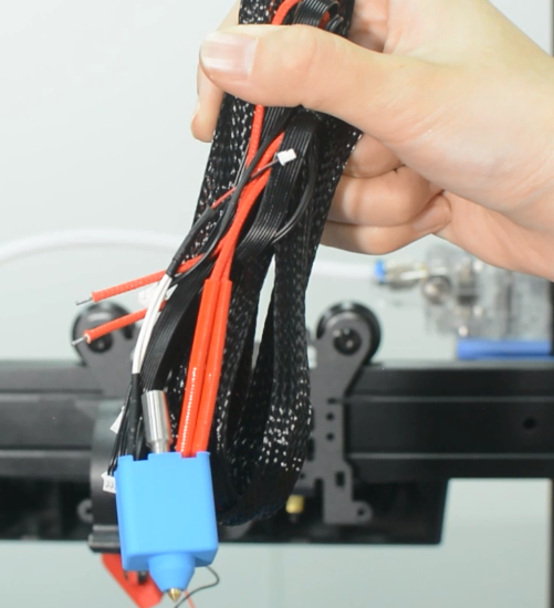
- c.Place back all the pieces to reassemble the print head. Use zip ties to manage the cables.
- d.Place back all the pieces to reassemble the print head. Make sure the cables are fully inserted and tightened!
- e.Connect the cables for hotend fan and hotend.
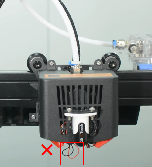
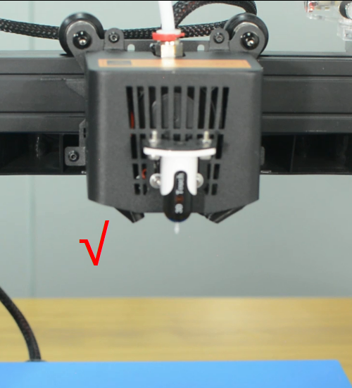
- Warning : Tie the wires properly, otherwise it will scratch the model during printing, leading the wires disconnected.
4. It's done. Heat up the printer and try it out.
How to replace the hotend
The hotend is available in our website: Thunder hotend
Prepare: Turn the printer off and unplug the power cable from the socket.
1. Disassemble the hotend kit
- a.Remove the PTFE tube and the hotend housing and disassemble the hotend fan.
- b.Release and remove the two screws that secure the hotend.
- c.Cut off the zip ties and be aware of not cutting the cables.
- d.Release the screw terminals for heater cartridge and remove the cables.
- Unplug the cables of hotend and the hotend fan.
2. Install the new hotend kit
- a.Install the new hotend to the bracket.
- b.Connect all the cables for hotend. Install the hotend housing.
- c.Connect the cables of hotend fan and hotend.
- d.Insert the both heater cables into the connector and tighten the screw terminals. Make sure the cables are fully inserted and tightened!
3. It's done. Heat up the printer and try it out.
How to replace the power supply
How to auto leveling
How to manual leveling
Trouble Shooting
How to upgarde UI
A TF card or USB flash drive is required to upgrade the UI of Thunder. See following steps:
Step 1: Copy the "System" folder to TF card or USB drive root menu.
Step 2: Insert the TF card or USB drive into Thunder, and then power on. At this time, you will see that the display screen is updating the UI. This process takes a long time, please wait patiently.
Step 3: When it prompts "Update succeeded", please remove the TF Card/ U-Disk and restart the printer. UI upgrade is complete.
Note: After UI upgrading, delete the "System" folder on the TF card or USB flash drive to avoid repeated UI upgrade during power-on.
How to upgarde firmware
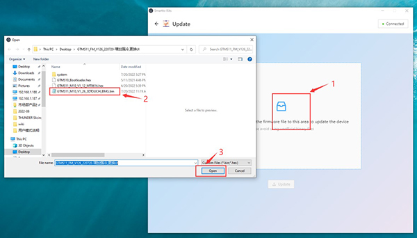
Thunder does not support TF card upgrading firmware directly. You need to use Smartto Kits to upgrade the firmware through the USB cable. The steps are as follows:
1.Install the CH340 driver (the TF card attached has the driver file, or you can search and download the CH340 driver from the Internet).
2.Plug the B-type interface of the USB cable into the printer and the other end into your computer.
3.Install Smartto Kits, then open Smartto Kits, select "Quick Start", then select "Update" to go to the firmware upgrade page.
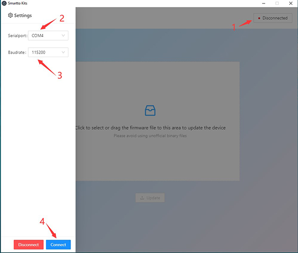
4.Click the "Disconnected" button in the upper right corner. The Setting sidebar is displayed in left side. Select the serial port for Thunder, set the serial port baud rate to 115200, and click "Connect" to Connect Thunder.
5.Click the blank space in the Update page and select the firmware you want to upgrade.
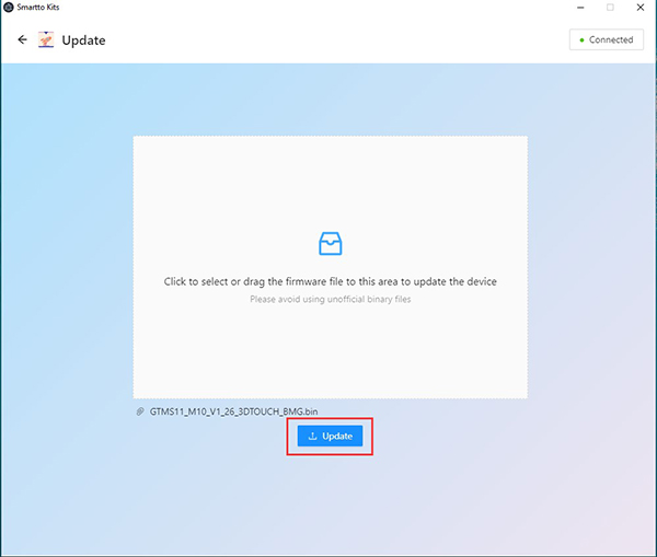
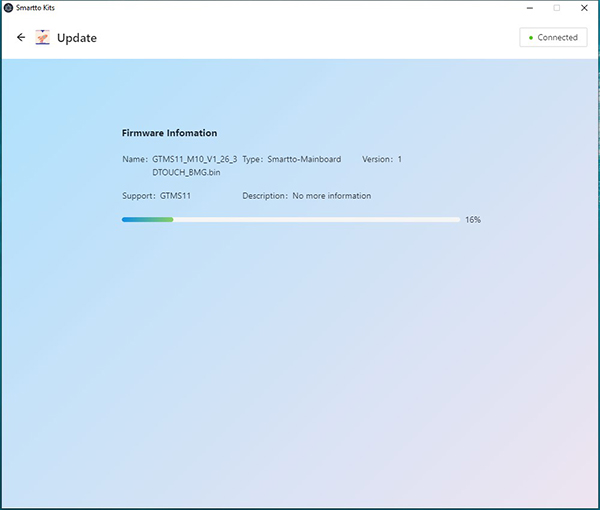
6.Click "Update" to start upgrading the firmware.
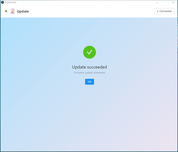
7.When it prompts "Update Succeeded", firmware upgrade completes.
How to use Smarttokits
In order to enable users to better use and adjust Thunder, we have opened the parameters of the core algorithm of Thunder firmware. Users can adjust the parameters of Thunder according to the usage scenarios and requirements to obtain better print quality. It should be noted that Thunder may also get worse print quality due to the adjusting of some parameters.
User mode requires using the Smartto Kits tool and modifying parameters via USB. Users can also export and share their configuration parameters with other users, or import parameters from other users into Thunder.
Here we provide a download link for the Smart Kits tool that you can download and use it by yourself. Here is how to use Smartto Kits.
1.Install the CH340 driver (the TF card attached with the printer has the driver file, or you can search and download the CH340 driver from the Internet).
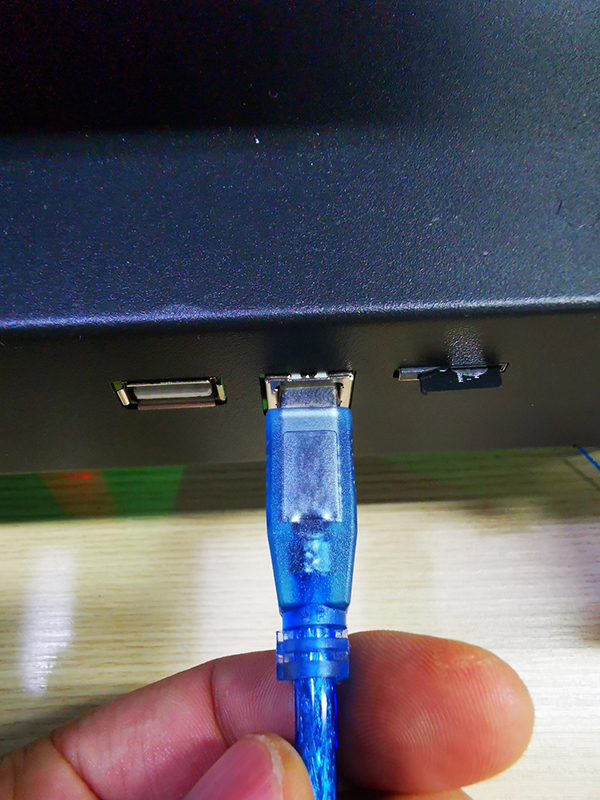
2.Plug the B-type interface of the USB cable into THUNDER and the other end into your computer.
3.Install Smartto Kits, open Smartto Kits, choose "Quck Start"
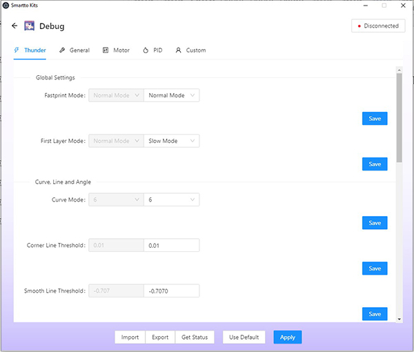
4.Choose "Debug" in the new page, enter User Mode parameter setting page.
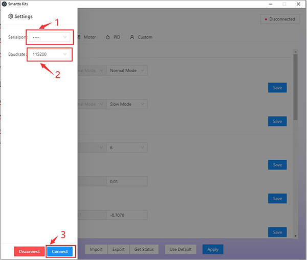
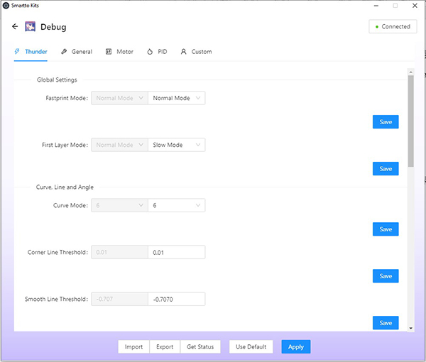
5.Click the "Disconnected" button in the upper right corner. The Setting interface is displayed in left side. Select the serial port for Thunder, set the serial port baud rate to 115200, and click "Connect" to Connect Thunder.
Smartto Kits Basic Menu Description
Import: Import Thunder configuration parameters
Export: Exports Thunder configuration parameters
Get Status: Reads the current parameters of Thunder
Use Default: Use the factory Default parameter of Thunder (print mode)
Save: The saved parameter is valid only for this time. The parameter becomes invalid after restart Thunder
Apply: Write the modified parameters to the Thunder Flash memory
Thunder UI parameters explanation Fastprint Mode
You can choose Normal mode, Fast mode, Crazy mode, User mode and Slow mode. Except User mode, all the parameters are preset by the printer. The user cannot edit them.
•First Layer Mode
Set the printing mode of the first layer (currently the default is 0.3mm height, all below is considered as the first layer). For some filament, high speed switching of the first layer will lead to poor adhesion of filament to the hot bed. It is necessary to lower the acceleration and deceleration so that the first layer can be enabled to print stably. The default mode is S4.
•Curve Mode
The default value ranges from 0 to 7. Different parameters affect the speed of the trajectory of the model. The speed of the trajectory decreases when the parameter ranges from 0 to 7, and the default value is 6.
S0~S3: the motion trajectory basically keeps running at high speed, and the speed decreases step by step; Suitable for some models, easy to cause model edge bulge; Enabling these modes will restrict the implementation of some algorithms, resulting in invalid parameter Settings.
S4~S7: The motion trajectory is slowed down to different degrees by coupling processing of multiple algorithms. The larger the parameter, the flatter the printing. It is generally recommended to use S5~S7, S4 in some models easy to cause jitter.
•Corner Line Threshold
Represents the length threshold of a small consecutive line segment at the junction of a corner (unit: mm). Line segments less than this value will have special treatment at the corner to prevent overshooting; Choosing different thresholds can well reduce the strong jitter problem caused by continuous short line segments (about 0.4~1.5mm line segments connected into a curved surface, circle or ellipse) and small angles at high speed; The parameter range is [0.01,100].
•Max Junction
Indicates the maximum startup speed when the corner between two commands is at a right Angle. When Mode 4-7 is selected in Curve Mode, the motion speed curve generated by the algorithm will shift upward or downward according to this value. The larger the parameter is, the faster the overall velocity is. Generally, the set value is between [6,40], and the unit is mm/s.
•Dynamic Acceleration(Minimum)
Represents the minimum preset acceleration of the printer, and the preset acceleration greater than this will be dynamically adjusted according to the bending degree of the movement trajectory. The value ranges from [500, 9000]. The value 9000 indicates that this function is disabled. Suitable for models that requires stable printing process.
•X/Y Frequency
Max Frequency (Hz) represents the upper limit of oscillation Frequency of X/Y axis. When the motion part set in the model moves back and forth, movements higher than this Frequency will decelerate accordingly. The frequency unit is Hz. This will effectively reduce the printer shock caused by printing small infill models. The frequency is limited to [0, 200].
Minimum Speed (%) Specifies the Minimum Speed factor that limits the Minimum amount of deceleration. Parameter range [0, 100].
•Acceleration
Compute Mode: If you choose Acceleration, adjusting the parameters of Print Acceleration and Travel Acceleration is valid. If you choose Total Acceleration , adjusting the Print Acceleration and Travel Acceleration is invalid.
Print Acceleration: Represents the default acceleration, the unit is mm/s2.
Travel Acceleration: Represents the acceleration of empty driving, the unit is mm/s2.
•Jerk
Jerk represents the starting speed of X/Y/E, where the maximum starting speed of X/Y/E can be set.
•Extruder
Max_advance_speed:Specify the upper limit of the pressure adjustment speed (LINE ADVANCE); Prevent the extruder from producing strong noise and abnormal discharge due to high speed; The parameter range is [0.1,35]; The default value is 16mm/s. Too high speed will cause extruder vibration, too low will cause printing acceleration reduction.
Advance K: Represents the K value of pressure regulation. The larger the value, the more extruder retraction will be. Generally, the remote extruder is set between [0.05,0.8], and the short-range extruder is set between [0.01,0.2].
General Page
Platform Size: Adjust printing volume. Since the machine structure already limited the volume, we don’t suggest users to change it.
Motor Page
Motor Step: Set step motor parameter
Motor Direction: Change the motor movement direction
Maximum Speed: The X/Y/Z axis and the extruder maximum speed of the are modified here. The maximum printing speed of the print cannot be changed here
Maximum Jerk: Change the maximum start speed of X/Y/Z axis and extruder
Maximum Acceleration: Setting or edit the maximum acceleration of X/Y/Z axis and the extruder
PID Page
Edit the PID parameter for extruder and hotbed.
Custom Page
On this page, users can send command directly.
How to print with Cura
Thunder printing speed can reach 300mm/s. In order to ensure the printing quality even in high speed, the correct setting of slicing parameters is essential. We recommend the Cura slicing software and provide Thunder configuration file for Cura slicing software on this page.
Cura slicing software download link: https://github.com/Ultimaker/Cura
We offered 2 configuration files for Thunder, see below about importing file to Cura software.
Thunder Cura 4.x Configuration
Thunder Cura 5.0&5.1 Configuration
For Cura 4.x version, the import path for the two configuration files is:
"geeetech_Thunder.def.json" put into
C:\Program Files\Ultimaker Cura 4.x\resources\definitions
"geeetech_Thunder_extruder.def" put into
C:\Program Files\Ultimaker Cura 4.13.1\resources\extruders
Copy file folder “geeetech” to Ultimaker Cura 4.13.1\resources\\quality
Copy the seven son files of variants folder to Ultimaker Cura 4.13.1\resources\\variants
For the Cura 5.x version, the import path for the two configuration files is:
"geeetech_Thunder.def.json" put into
C:\Program Files\Ultimaker Cura 5.1.0\share\cura\resources\definitions
"geeetech_Thunder_extruder.def" put into
C:\Program Files\Ultimaker Cura 5.1.0\share\cura\resources\extruders
Copy file folder “geeetech” to Ultimaker Cura 5.X\share\cura\resources\quality
Copy the seven son files of variants folder to Ultimaker Cura 5.X\share\cura\resources\variants
Turn the printer on but the screen is black
Warning: Never install or unplug anything on a printer while it’s being powered!
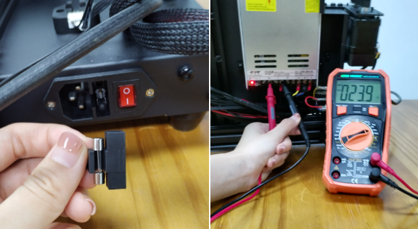
(a)Check if the power supply is working normally. The red indicator on the switch should be light. And also check the fuse in the little black box, it should be complete without burns. Please measure the output voltage, which should be around 24 Volts.
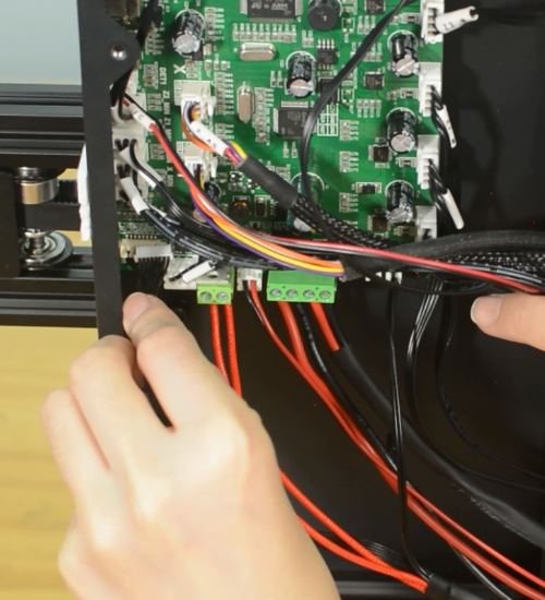
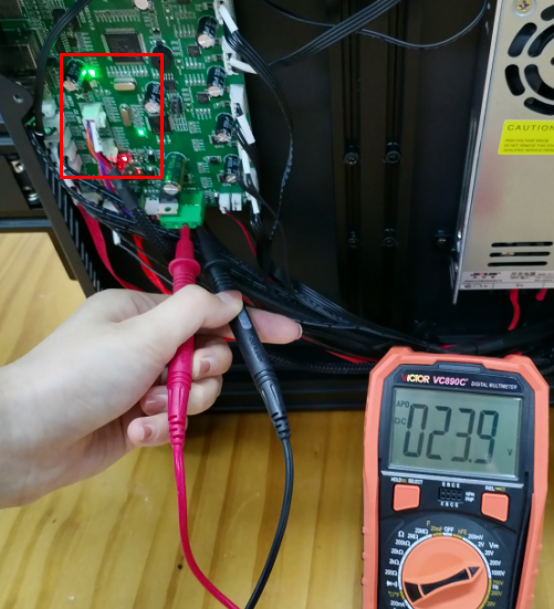
(b)Check if the control board is working normally. There’re two green LEDs and one red LED working as the picture shown below. Measure the input voltage of the control board, it should be around 24 Volts.
(c)Make sure the screen is connected properly.
The extruder keeps making a click sound
(a)Decrease the print speed. If the print speed is too fast, the extruder will push the filament too quickly. Filament may not have enough time to melt and even clog in the nozzle. A clogged nozzle will then exert pressure back on the extruder, resulting in clicking. For PLA, our recommended print speed is under 250 mm/s.
(b)Increase the print temperature. If the temperature is too low, it will not melt the filament properly. This can also clog the nozzle. As the extruder is no longer able to push the filament ahead, it starts “slipping”.
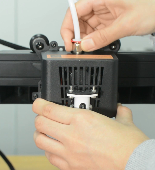
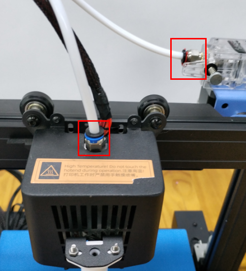
(c)Check the pneumatic fittings. A loose coupling could therefore allow molten filament to leak into a gap between the tube and the nozzle. This will restrict the flow of the filament, causing the extruder keep clicking.
(d)Change the extruder gear. After many hours of use, the teeth of the extruder may eventually wear out. Thus, it can no longer hold the filament, leading to filament slipping in the extruder.
(e)A low-tension extruder arm bar. If spring tension is too low, the extruder gear will not properly grip the filament. This leads to filament grinding.
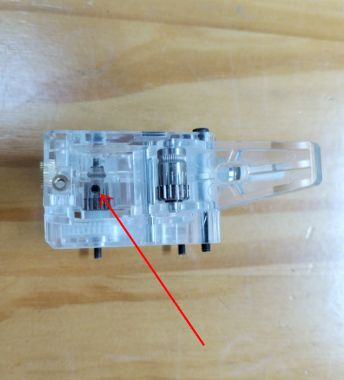
(f)Check if the grub screw on the extruder gear. If the grub screw is loose, the gears will fail to grab the filament.
Nothing is printing
(a)Nozzle is too close to the hotbed
Even though the extruder is working but no filament is depositing on the hotbed, Check if the nozzle is too close to the hotbed. Adjust the Z-offset value slightly will help.
(b)Print temperature is too low
Some filament needs more higher temperature, manually feed the filament, if it can not be extruded, please try increase the print temperature.
(c)The extruder is not working
Check if the grub screw on the extruder gear. If the grub screw is loose, the gears will fail to grab the filament when feeding into the hotend. Also check if the extruder motor is connected properly.
Mintemp error
The Mintemp error in 3D printers is a design feature within your firmware for safety in regard to temperature. When below a set temperature, the heater will be switched off due to possibly having a broken thermistor wire. It can be observed a negative the temperature on the LCD screen.
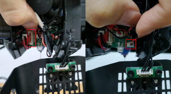
Check if the hot end connector and thermistor are connected properly as the pictures below. Check the hotend cables and thermistor, make sure they’re not broken or burn out.
You can test the thermistor by a multimeter. If it fails to read the resistance, then the wire is broken. At room temperature, it should be 80 kΩ - 125 kΩ. Or apply heat to the thermistor with a heater, blow-dryer or other heating device.
The resistance should decline steadily in seconds if it works. If not, replace it.
Another common reason behind getting the MINTEMP error is from being in a cold environment, especially in winter months. Your 3D printer is designed to have a minimum temperature that it can operate in as a safety feature.
Automatic leveling failed
(a)3D Touch is abnormal
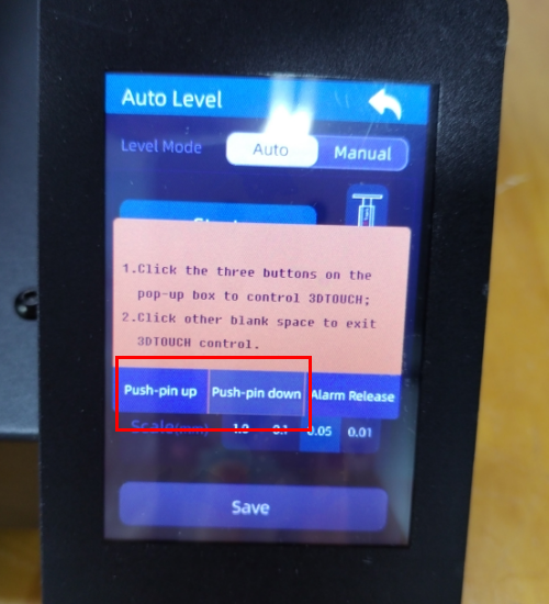
Check if the 3D Touch cables are connected properly. You can use the “Test” function to check if the 3D Touch is working normally.
(b)Homing failed
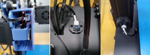
Check the X, Y and Z axes end stops, make sure they’re all connected properly. Note the photoelectric end stops on the Y and Z axes, which normally have a blue signal light. You can home the X, Y and Z axes one by one to check which axis is faulty.
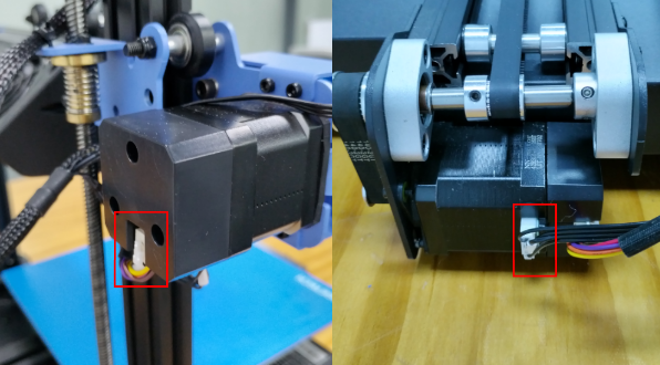
Also check the X and Y axes closed loop motor connections.
(c)The first layer is messy
Please clean the hotbed before printing, this will help to get a good adhesion. We recommend a thicker first layer, 0.3 mm is good. If these’re not helpful, please try to adjust the Z-offset. What’s more, you can try adjust the hotbed temperature, for example, the Geeetech wood PLA needs a lower hotbed temperature but PETG needs higher.
Spring steel sheet problem
The spring steel sheet is flexible and easy for part removal. But keep in mind that prints are easy to remove after the plate cools down. Don’t try to forcefully remove the object when the sheet is still hot. We do not suggest you use the adhesive on the sheet, because the adhesive is difficult to clean up and may have an opposite effect.
If there’re leftover residue on the sheet, preheat the hotbed to 80 degrees to make the plastic soft. Then use the wet cloth wiping the plate and gently scrap the residue off.
A dirty bed will cause poor first layer adhesion. You need to remove the dirt, leftover residue or oil from the bed surface. Isopropyl alcohol (IPA) 90%+ will help to degrease the platform.
Filament sensor
If there’s error on the screen prompts like “Change Filament” even filament has been uploaded, maybe the sensor is broken. You can test it by a multimeter.
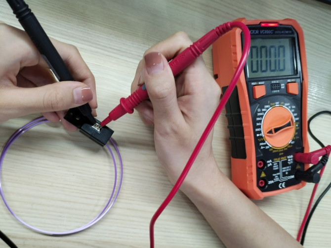
Remember load a small piece of filament through the sensor before test. By touching each of the measurement leads of the multimeter to the two pins of the sensor, a signal (beep or 0 value on the multimeter screen) will indicate that the component is intact and therefore, should work.
Nozzle discharge abnormality
1. Filament is knotted and stuck, and the feeding is not smooth.
2. The nozzle temperature is too low and does not reach the required melting temperature of filament.
3. There is carbonization residue in the nozzle, please replace the spare nozzle.
4. The heat dissipation of the nozzle is insufficient, resulting in the filament in the upper part of the pipe melting in advance, and the extrusion force is insufficient. Please check whether the cooling fan works normally.
5. The printing speed of model slices is too fast, and the nozzle extrusion speed cannot keep up with it. Please reduce the speed.
6. If the nozzle extrusion is not smooth due to scraping, please use the nozzle cleaner to dredge the nozzle after preheating.
The extruder gear slips and makes abnormal noise
1. Nozzle blocking, refer to the "nozzle discharge abnormality" treatment.
2. Check whether the friction force of extruder gear to filament is enough, please clean up the gear residue.
First layer abnormal
1. The first layer does not stick: the nozzle is too far away from the hot bed, please adjust the hotbed leveling again.
2. The first layer is not discharging, and the hot bed has scratches: the nozzle is too close to the hot bed, which is easy to damage the nozzle. Please level it again and check whether the discharging of the nozzle is normal.
Layer shift
1. The printing speed of model slices is too fast, please reduce the printing speed.
2. The belt of X axis or Y axis is too loose, please adjust the belt tightness.
3. X axis or Y axis synchronization wheel is not secured, please adjust the machine meter on the synchronization wheel.
X/Y axis Closed-loop Control Abnormality
During the using of THUNDER, if the X-axis or Y-axis is stuck in the process of movement, it may be caused by the following two reasons after excluding the non-pulley structure and improper connection of wiring:
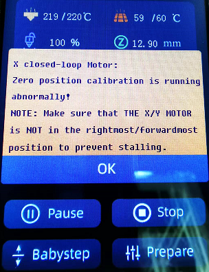
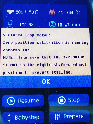
1. The X-axis motor or Y-axis closed-loop control sensor is not calibrated or the calibration parameters fail, the closed-loop control sensor of the corresponding axis needs to be re-calibrated.
2.The magnet of the closed-loop control unit of the X-axis motor or Y-axis motor is loose or falls off. The magnet needs to be fixed on the motor shaft with glue again.
=='Filament'==
Does Thunder require high-speed PLA filament to achieve high-speed printing?
No, Thunder is designed to achieve high-speed printing with ordinary PLA filaments, so Thunder can achieve high-speed printing with ordinary PLA filaments.
G-code for part cooling fan and auxiliary part cooling fan
Part Cooling Fan:
M106 P0 S383 ; ON MainFan 150%
M106 P0 S255 ; ON MainFan 100%
M106 P0 S128 ; ON MainFan 50%
Auxiliary Part Cooling Fan:
M106 P1 S255 ; ON Aux Fan 100%
M106 P1 S128 ; ON Aux Fan 50%
M106 P1 S0 ; OFF Aux Fan
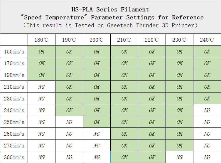
HS-PLA Series Filament "Speed-Temperature" Parameter Settings for Reference
HS-PLA is Geeetech's latest high-speed printing filament. By adjusting the melting point, melting index, glass transition temperature of raw materials and optimizing the production process, Geeetech enables HS-PLA to have stronger fluidity, smoother discharge, faster curing and forming speed and is not easy to deform under the melting condition. Compared with ordinary PLA, HS-pla has the advantages of faster printing speed, higher printing quality and more delicate model surface, which can better meet the high performance requirements of high-speed 3D printers for filament.
Due to the differences in slicing parameters, environment and printers, the following table is for reference only.
HS-PLA Series Filament "Speed-Temperature" Parameter Settings for Reference
X/Y Axis Closed-loop Motor Calibration and Abnormality Elimination
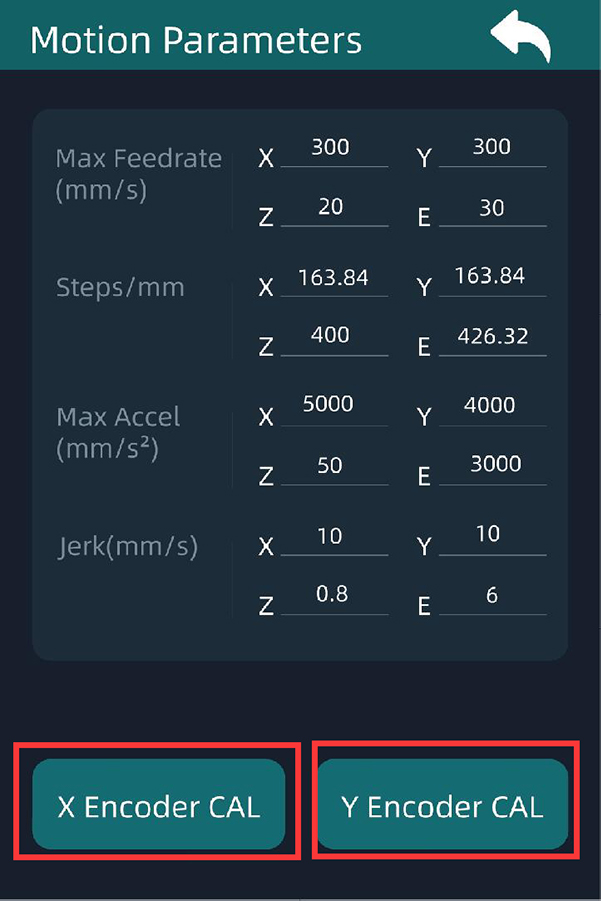
X and Y axis motor are all closed-loop controlled, and the closed-loop control sensors on the motors have been calibrated before delivery. Do not remove the closed-loop control sensor if the X-axis and Y-axis are not abnormal. Otherwise it will cause the calibration parameters of the closed-loop control sensor on the X-axis and Y-axis to be offset, resulting in the X-axis or Y-axis stuttering or abnormal jitter during the printing process.
On the screen menu, we provide the X-axis and Y-axis closed-loop control sensor calibration function. The specific path is "Operate" → "Motion". In the "Motion" menu, you can see two buttons "X Encoder Cal" and "Y Encoder Cal". They are X-axis and Y-axis closed-loop control sensor calibration buttons respectively. The specific calibration methods are as follows:
X axis: First, ensure that the hot end can move smoothly on the X axis, and then move the hot end to the middle of the X axis. Then click the "X Encoder Cal" button, and the control panel will pop up to prompt whether to confirm the calibration of the X axis closed-loop control sensor. Choose "YES", and the hot end will move first to the right and then to the left. When the hot end stops, the calibration is complete, and the UI will prompt that the calibration is complete.
Y axis: First, ensure that the hot bed can move smoothly on the Y-axis. Then, move the hot bed to the middle position of the Y-axis, and then click "Y Encoder Cal" button. The control panel will pop up to prompt whether to confirm the calibration of the Y-axis closed-loop control sensor. When the hot end stops, the calibration is complete, and the UI will prompt that the calibration is complete.
