Difference between revisions of "Rambo"
(→FAQS) |
(→Rambo family) |
||
| (21 intermediate revisions by the same user not shown) | |||
| Line 34: | Line 34: | ||
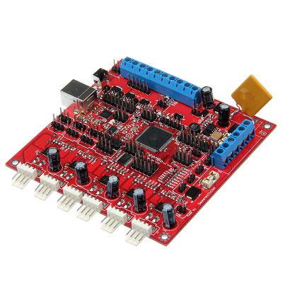
RAMBo (RepRap Arduino-compatible Mother Board) is an all in one RAMPS class motherboard targeting convenience, reliability, and performance.Our version is 1.2a. | RAMBo (RepRap Arduino-compatible Mother Board) is an all in one RAMPS class motherboard targeting convenience, reliability, and performance.Our version is 1.2a. | ||
| + | |||
| + | |||
| + | [[File:Rambo-conn-all.jpg|500px|]] | ||
| Line 39: | Line 42: | ||
weight:80g | weight:80g | ||
| − | |||
==Software Resources== | ==Software Resources== | ||
| − | Compiling environment: | + | Compiling environment: [http://www.geeetech.com/wiki/images/3/36/Arduino-1.0.5-r2-windows.zip Arduino IDE] |
| − | |||
| − | |||
| − | + | Firmware: [http://www.geeetech.com/wiki/images/3/39/Marlin-Marlin_v1.zip Marlin] | |
| − | + | PC Software:[http://www.geeetech.com/wiki/images/e/e1/Printrun-Win-Slic3r-10Mar2014.zip printrun][http://www.geeetech.com/wiki/images/3/36/SetupRepetierHost_1_00.zip Repetier-Host] | |
| − | |||
| − | |||
=Interfaces= | =Interfaces= | ||
| Line 64: | Line 62: | ||
6 interfaces for end stop(X/Y/Z min, X/Y/Z max)which can be connected with mechanical or optical end stop, or hall sensor. | 6 interfaces for end stop(X/Y/Z min, X/Y/Z max)which can be connected with mechanical or optical end stop, or hall sensor. | ||
| − | = | + | ==Pins== |
| − | |||
| − | |||
| − | |||
| − | |||
| − | |||
| − | |||
| − | |||
| − | |||
| − | |||
| − | |||
| − | |||
| − | |||
| − | |||
| − | |||
| − | |||
| − | |||
| − | |||
| − | |||
| − | |||
| − | |||
| − | |||
| − | |||
| − | |||
| − | |||
| − | |||
| − | |||
| − | |||
| − | |||
| − | |||
| − | |||
| − | |||
| − | |||
| − | |||
| − | |||
| − | |||
| − | |||
| − | |||
| − | |||
| − | |||
| − | |||
| − | |||
| − | |||
| − | |||
| − | |||
| − | |||
| − | |||
| − | |||
| − | |||
| − | |||
| − | |||
| − | |||
| − | |||
| − | |||
| − | |||
| − | |||
| − | |||
| − | |||
| − | |||
| − | |||
| − | |||
| − | |||
| − | |||
| − | |||
| − | |||
| − | |||
| − | |||
| − | |||
| − | |||
| − | |||
| − | |||
| − | |||
| − | |||
| − | |||
| − | |||
| − | |||
| − | |||
| − | |||
| − | |||
| − | |||
| − | |||
| − | |||
| − | |||
| − | |||
| − | |||
| − | |||
| − | |||
| − | |||
| − | |||
| − | |||
| − | |||
| − | |||
| − | |||
| − | |||
| − | |||
| − | |||
| − | |||
| − | |||
| − | |||
| − | |||
| − | |||
| − | |||
| − | |||
| − | |||
| − | |||
| − | |||
| − | |||
| − | |||
| − | |||
| − | |||
| − | |||
| − | |||
| − | |||
| − | |||
| − | |||
| − | |||
| − | |||
| − | |||
| − | |||
| − | |||
| − | |||
| − | |||
| − | |||
| − | |||
| − | |||
| − | |||
| − | |||
| − | |||
| − | |||
| − | |||
| − | |||
| − | |||
| − | |||
| − | |||
| − | |||
| − | |||
| − | |||
| − | |||
The extension headers are in the format "Extension Name" "Pin Number" "Function". Example: MX1-5 Direction = "Motor Extension 1" "Pin 5". | The extension headers are in the format "Extension Name" "Pin Number" "Function". Example: MX1-5 Direction = "Motor Extension 1" "Pin 5". | ||
{| border="1" | {| border="1" | ||
| Line 710: | Line 571: | ||
| VCC | | VCC | ||
|} | |} | ||
| + | |||
| + | ==LCD panel support == | ||
| + | |||
| + | There is now a fairly easy method for using a Smart Lcd with a Rambo board. See RamboLCD for instuctions. | ||
| + | |||
| + | =Fuses and lockbits= | ||
| + | 32u2 fuses - | ||
| + | BODLEVEL = 3V0; | ||
| + | HWBE = [X]; | ||
| + | DWEN = [ ]; | ||
| + | RSTDISBL = [ ]; | ||
| + | SPIEN = [X]; | ||
| + | WDTON = [ ]; | ||
| + | EESAVE = [ ]; | ||
| + | BOOTSZ = 2048W_3800; | ||
| + | BOOTRST = [ ]; | ||
| + | CKDIV8 = [ ]; | ||
| + | CKOUT = [ ]; | ||
| + | SUT_CKSEL = EXTXOSC_8MHZ_XX_16KCK_4MS1 | ||
| + | |||
| + | EXTENDED = 0xF4; | ||
| + | HIGH = 0xD9; | ||
| + | LOW = 0xEF | ||
| + | |||
| + | 2560 Fuses | ||
| + | BODLEVEL = 2V7; | ||
| + | OCDEN = [ ]; | ||
| + | JTAGEN = [ ]; | ||
| + | SPIEN = [X]; | ||
| + | WDTON = [ ]; | ||
| + | EESAVE = [X]; | ||
| + | BOOTSZ = 4096W_1F000; | ||
| + | BOOTRST = [X]; | ||
| + | CKDIV8 = [ ]; | ||
| + | CKOUT = [ ]; | ||
| + | SUT_CKSEL = EXTXOSC_8MHZ_XX_16KCK_65MS | ||
| + | |||
| + | EXTENDED = 0xFD; | ||
| + | HIGH = 0xD0; | ||
| + | LOW = 0xFF; | ||
| + | |||
| + | Lock bits for both only set BLB1 = LPM_SMP_DISABLE (0x0F). | ||
| + | |||
| + | =Heated bed maximum voltage= | ||
| + | The heated bed circuit's voltage is limited by the RGEF1400 PTC fuse which is rated to 16V. If a higher voltage is required this fuse can be replaced with a jumper wire and off board fuse holder. Make sure that your wire and solder are sufficient to carry the high current of this rail. | ||
| + | |||
| + | =Motor Current= | ||
| + | The current for the stepper motors is set by firmware controlling the 8-bit digital potentiometer. The following formula from the [http://www.allegromicro.com/Products/Motor-Driver-And-Interface-ICs/Bipolar-Stepper-Motor-Drivers/~/media/Files/Datasheets/A4982-Datasheet.ashx Allegro datasheet] describes how to set the reference voltage: I<small><sub>TripMAX</sub></small> = V<small><sub>REF</sub></small>/(8 X R<small><sub>S</sub></small>). R<small><sub>S</sub></small>, the value of the sense resistor on RAMBo is equal to 0.1<math>\Omega</math>. I<small><sub>TripMAX</sub></small> is the current the stepper motors are rated for. Ideally you should start with 70%-90% of maximum. You can verify the voltage for each driver by plugging the reference voltage (V<small><sub>REF</sub></small>) measured at the X_REF test point (Y_REF,etc for the other drivers) in the following formula: | ||
| + | |||
| + | <math> V_{Ref}= I_{TripMAX} \times 0.8</math> | ||
| + | |||
| + | Note the A4982 is set to be limited to 2A. This means the adjustable voltage range is 0 to 1.66 volts. The following formula will yield the 8-bit binary value, <math>W_v</math>, to be entered into firmware or directly over SPI. | ||
| + | |||
| + | <math>W_v = \frac{V_{Ref}}{1.66} \times 255</math> | ||
=Fuses= | =Fuses= | ||
| Line 724: | Line 639: | ||
Before uploading, driver should be installed for windows. Then choose the type of board: Tools > Board > Arduino Mega 2560 or Mega ADK. (Picture below) | Before uploading, driver should be installed for windows. Then choose the type of board: Tools > Board > Arduino Mega 2560 or Mega ADK. (Picture below) | ||
| + | [[File:Rumba9.jpg|500px|]] | ||
Select the serial port: Tools > Serial Port, the serial port for Rambo is usually the last one. | Select the serial port: Tools > Serial Port, the serial port for Rambo is usually the last one. | ||
| − | + | [[File:Rumba10.jpg]] | |
| − | Click | + | |
| + | Click [[File:button1.jpg]] to check if there is any mistake. If not, click [[File:button2.jpg]] to upload. | ||
| + | [[File:Rumba 11.jpg]] | ||
During the process of uploading, the 3 LEDs corresponding to TX, RX and L on mega board will blink, if the blink stops, the uploading is done. | During the process of uploading, the 3 LEDs corresponding to TX, RX and L on mega board will blink, if the blink stops, the uploading is done. | ||
| + | [[File:Rumba 12.jpg]] | ||
After the uploading, you can go on with the next step. If the uploading is unsuccessful, read the error report on IDE, figure out the problem, and then try again. Some frequent errors are: a wrong select of board type and serial port. | After the uploading, you can go on with the next step. If the uploading is unsuccessful, read the error report on IDE, figure out the problem, and then try again. Some frequent errors are: a wrong select of board type and serial port. | ||
| − | |||
| − | |||
=Get Started= | =Get Started= | ||
| Line 796: | Line 713: | ||
These parameters are crucial to the printing size. These parameters indicate the pulse the axis need when operating 1mm. they are corresponding to x, y, z axis and extruder respectively. In most cases these figure should be calculated by yourself, you can refer to: http://calculator.josefprusa.cz/#steppers. | These parameters are crucial to the printing size. These parameters indicate the pulse the axis need when operating 1mm. they are corresponding to x, y, z axis and extruder respectively. In most cases these figure should be calculated by yourself, you can refer to: http://calculator.josefprusa.cz/#steppers. | ||
| − | + | ||
| + | So far, the commonest parameters have been configured and the printer can work now. In addition, if the 2004 LCD needs verifying, you should delete the “//” from “//#define REPRAP_DISCOUNT_SMART_CONTROLLER” to ensure the normal working. | ||
=FAQS= | =FAQS= | ||
| Line 838: | Line 756: | ||
32bits windows: | 32bits windows: | ||
| − | mdmcpq.inf_x86.rar [[Media:http://www.arduino.cn/forum.php?mod=attachment&aid=MTIzMHw2ZjJkZDY1OXwxNDA0NzAyMDgxfDY0MDF8MjQ4NQ%3D%3D]] | + | mdmcpq.inf_x86.rar [[Media:(http://www.arduino.cn/forum.php?mod=attachment&aid=MTIzMHw2ZjJkZDY1OXwxNDA0NzAyMDgxfDY0MDF8MjQ4NQ%3D%3D)]] |
| Line 845: | Line 763: | ||
mdmcpq.inf_amd64.rar [[Media:(http://www.arduino.cn/forum.php?mod=attachment&aid=MTIzMXxkN2QxMzdiMHwxNDA0NzAyMDgxfDY0MDF8MjQ4NQ%3D%3D) | mdmcpq.inf_amd64.rar [[Media:(http://www.arduino.cn/forum.php?mod=attachment&aid=MTIzMXxkN2QxMzdiMHwxNDA0NzAyMDgxfDY0MDF8MjQ4NQ%3D%3D) | ||
]] | ]] | ||
| − | + | ||
D. Reinstall driver step-by-step. | D. Reinstall driver step-by-step. | ||
| Line 875: | Line 793: | ||
After the restart of the system, you can install the driver and the installation method is the same with that of windows 7. | After the restart of the system, you can install the driver and the installation method is the same with that of windows 7. | ||
| − | = | + | |
| − | + | ||
| + | ==Files== | ||
| + | |||
| + | RAMBo-manual: | ||
| + | |||
| + | [[File:RAMBo-manual.pdf]] | ||
| + | |||
| + | RAMBo silk: | ||
| + | |||
| + | [[File:RAMBo0619silk.pdf]] | ||
| + | |||
| + | [[File:Controller_final_reprapdiscount.PDF]] | ||
| + | |||
| + | [[File:Rambo-LCD.pdf]] | ||
| + | |||
| + | =Rambo family= | ||
| + | [http://www.geeetech.com/rambo-reprap-arduinocompatible-mother-board-v11a-p-686.html RAMBo V1.2a] | ||
| + | |||
| + | [http://www.geeetech.com/reprap-rambo-12g-controller-board-p-879.html Rambo 1.2G] | ||
| + | |||
| + | Compared with the 1.1b version,Rambo 1.2G has the following updates: | ||
| + | 1. Increased ESD (Electro-Static discharge) Electrostatic Discharge in the USB circuit section | ||
| + | 2. The logical part of the circuit and MOSFET share the same power supply | ||
| + | 3. enhanced anti-interference ability of signals. | ||
Latest revision as of 10:31, 17 October 2014
Contents
Introduction
Rambo(RepRap Arduino-compatible Mother Board)is a microcontroller board of 3D printer which integrates the stepper motor, hotbed, extruder, fan driver and thermometry in one. Rambo is completely compatible with Arduino in that it adapts the same IC, ATMEGA 2560, with Arduino mega2560. 3 additional resettable fuses are added to Rambo to protect it from over current. What’s more, the motor drive current can be controlled with code. The present popular LCDs that Rambo supports are smart controller 2004 and 12864.
Features:
1. Adopting the IC atmega2560 and atmega16u2 that are completely compatible with Arduino
2. 4 interface for thermometry.
3. All interfaces of 2560 and 16u2 are broken out for external use
4. 2 channel of sdramps that is compatible with SPI
5. 5 a4982 of 1/16 step size, 1 for X/Y axis respectively, 2 for Z axis, 2 for extruder.
6. Every control signal of stepper motor has a test point
7. The step size of stepper driver can be divided by firmware.
8. Reserved interface for LCD
9. 5 channel of PWM for extruder control
10. 3 power inputs source that is protected by resettable fuses: 12v 15a for hotbed; 12v 5a for extruder; 12v 5a for stepper motor.
11. PCB is composed of 4 layer of 35um copper sheet
Overview and Hardware Resources
RAMBo (RepRap Arduino-compatible Mother Board) is an all in one RAMPS class motherboard targeting convenience, reliability, and performance.Our version is 1.2a.
size:102mm*104mm
weight:80g
Software Resources
Compiling environment: Arduino IDE
Firmware: Marlin
PC Software:printrunRepetier-Host
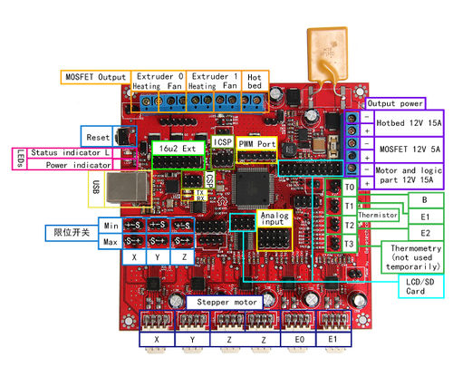
Interfaces
Interface Layout
Interface specifications
4 ADC interfaces (one for hotbed, 2 for extruder and one for thermometry)
5 PWM: 2 for extruder, 2 for fan control and 1 for heatbed
6 interfaces for end stop(X/Y/Z min, X/Y/Z max)which can be connected with mechanical or optical end stop, or hall sensor.
Pins
The extension headers are in the format "Extension Name" "Pin Number" "Function". Example: MX1-5 Direction = "Motor Extension 1" "Pin 5".
| Pin Number | Pin Name | Arduino Pin Name | RAMBO Function |
| 1 | PG5 ( OC0B ) | Digital pin 4 (PWM) | PWM-Ext 6 |
| 2 | PE0 ( RXD0/PCINT8 ) | Digital pin 0 (PWM) (RX0) | USB – serial comms, SER0 3 |
| 3 | PE1 ( TXD0 ) | Digital pin 1 (PWM) (TX0) | USB – serial comms, SER0 4 |
| 4 | PE2 ( XCK0/AIN0 ) | Ext2 20 | |
| 5 | PE3 ( OC3A/AIN1 ) | Digital pin 5 (PWM) | PWM-Ext 5 |
| 6 | PE4 ( OC3B/INT4 ) | Digital pin 2 (PWM) | PWM-Ext 4 |
| 7 | PE5 ( OC3C/INT5 ) | Digital pin 3 (PWM) | Bed Heater |
| 8 | PE6 ( T3/INT6 ) | Ext2 18 | |
| 9 | PE7 ( CLKO/ICP3/INT7 ) | Ext2 16 | |
| 10 | VCC | VCC | VCC |
| 11 | GND | GND | GND |
| 12 | PH0 ( RXD2 ) | Digital pin 17 (PWM) (RX2) | Serial 7 |
| 13 | PH1 ( TXD2 ) | Digital pin 16 (PWM) (TX2) | Serial 8 |
| 14 | PH2 ( XCK2 ) | Ext2 8 | |
| 15 | PH3 ( OC4A ) | Digital pin 6 (PWM) | Fan 1 |
| 16 | PH4 ( OC4B ) | Digital pin 7 (PWM) | Heat 1 |
| 17 | PH5 ( OC4C ) | Digital pin 8 (PWM) | Fan 0 |
| 18 | PH6 ( OC2B ) | Digital pin 9 (PWM) | Heat 0 |
| 19 | PB0 ( SS/PCINT0 ) | Digital pin 53 (PWM)(SPI-SS) | SPI-Ext SS 6 |
| 20 | PB1 ( SCK/PCINT1 ) | Digital pin 52 (PWM)(SCK) | SPI-Ext SCK 5 |
| 21 | PB2 ( MOSI/PCINT2 ) | Digital pin 51 (PWM)(MOSI) | SPI-Ext MOSI 4 |
| 22 | PB3 ( MISO/PCINT3 ) | Digital pin 50(MISO) | SPI-Ext MISO 3 |
| 23 | PB4 ( OC2A/PCINT4 ) | Digital pin 10 (PWM) | Z Min Endstop |
| 24 | PB5 ( OC1A/PCINT5 ) | Digital pin 11 (PWM) | Y Min Endstop |
| 25 | PB6 ( OC1B/PCINT6 ) | Digital pin 12 (PWM) | X Min Endstop |
| 26 | PB7 ( OC0A/OC1C/PCINT7 ) | Digital pin 13 (PWM) | LED, PWM-Ext 3 |
| 27 | PH7 ( T4 ) | Ext2 6 | |
| 28 | PG3 ( TOSC2 ) | Ext3 7 | |
| 29 | PG4 ( TOSC1 ) | Ext3 5 | |
| 30 | RESET | RESET | Reset |
| 31 | VCC | VCC | VCC |
| 32 | GND | GND | GND |
| 33 | XTAL2 | XTAL2 | XTAL2 |
| 34 | XTAL1 | XTAL1 | XTAL1 |
| 35 | PL0 ( ICP4 ) | Digital pin 49 | Y Direction |
| 36 | PL1 ( ICP5 ) | Digital pin 48 | X Direction |
| 37 | PL2 ( T5 ) | Digital pin 47 | Z Direction |
| 38 | PL3 ( OC5A ) | Digital pin 46 (PWM) | MX3-5 Direction |
| 39 | PL4 ( OC5B ) | Digital pin 45 (PWM) | MX2-5 Direction |
| 40 | PL5 ( OC5C ) | Digital pin 44 (PWM) | MX1-5 Direction |
| 41 | PL6 | Digital pin 43 | E0 Direction |
| 42 | PL7 | Digital pin 42 | E1 Direction |
| 43 | PD0 ( SCL/INT0 ) | Digital pin 21 (SCL) | I2C SCL |
| 44 | PD1 ( SDA/INT1 ) | Digital pin 20 (SDA) | I2C SDA |
| 45 | PD2 ( RXDI/INT2 ) | Digital pin 19 (RX1) | Serial 5 |
| 46 | PD3 ( TXD1/INT3 ) | Digital pin 18 (TX1) | Serial 6 |
| 47 | PD4 ( ICP1 ) | Ext2 14 | |
| 48 | PD5 ( XCK1 ) | Ext2 12 | |
| 49 | PD6 ( T1 ) | Ext2 10 | |
| 50 | PD7 ( T0 ) | Digital pin 38 | Digipot SS |
| 51 | PG0 ( WR ) | Digital pin 41 | X Microstep2 |
| 52 | PG1 ( RD ) | Digital pin 40 | X Microstep1 |
| 53 | PC0 ( A8 ) | Digital pin 37 | X Step |
| 54 | PC1 ( A9 ) | Digital pin 36 | Y Step |
| 55 | PC2 ( A10 ) | Digital pin 35 | Z Step |
| 56 | PC3 ( A11 ) | Digital pin 34 | E0 Step |
| 57 | PC4 ( A12 ) | Digital pin 33 | E1 Step |
| 58 | PC5 ( A13 ) | Digital pin 32 | MX1-4 Step |
| 59 | PC6 ( A14 ) | Digital pin 31 | MX2-4 Step |
| 60 | PC7 ( A15 ) | Digital pin 30 | Z Max, MX3-4 Step |
| 61 | VCC | VCC | VCC |
| 62 | GND | GND | GND |
| 63 | PJ0 ( RXD3/PCINT9 ) | Digital pin 15 (RX3) | Serial 9 |
| 64 | PJ1 ( TXD3/PCINT10 ) | Digital pin 14 (TX3) | Serial 10 |
| 65 | PJ2 ( XCK3/PCINT11 ) | Ext2 9 | |
| 66 | PJ3 ( PCINT12 ) | Ext2 11 | |
| 67 | PJ4 ( PCINT13 ) | Ext2 15 | |
| 68 | PJ5 ( PCINT14 ) | Ext2 17 | |
| 69 | PJ6 ( PCINT 15 ) | Ext2 19 | |
| 70 | PG2 ( ALE ) | Digital pin 39 | Y Microstep2 |
| 71 | PA7 ( AD7 ) | Digital pin 29 | X Enable |
| 72 | PA6 ( AD6 ) | Digital pin 28 | Y Enable |
| 73 | PA5 ( AD5 ) | Digital pin 27 | Z Enable |
| 74 | PA4 ( AD4 ) | Digital pin 26 | E0 Enable |
| 75 | PA3 ( AD3 ) | Digital pin 25 | E1 Enable |
| 76 | PA2 ( AD2 ) | Digital pin 24 | X Max, MX3-3 Enable |
| 77 | PA1 ( AD1 ) | Digital pin 23 | Y Max, MX2-3 Enable |
| 78 | PA0 ( AD0 ) | Digital pin 22 | MX1-3 Enable |
| 79 | PJ7 | Ext2 13 | |
| 80 | VCC | VCC | VCC |
| 81 | GND | GND | GND |
| 82 | PK7 ( ADC15/PCINT23 ) | Analog pin 15 | Y Microstep1 |
| 83 | PK6 ( ADC14/PCINT22 ) | Analog pin 14 | Z Microstep1 |
| 84 | PK5 ( ADC13/PCINT21 ) | Analog pin 13 | Z Microstep2 |
| 85 | PK4 ( ADC12/PCINT20 ) | Analog pin 12 | E0 Microstep2 |
| 86 | PK3 ( ADC11/PCINT19 ) | Analog pin 11 | E0 Microstep1 |
| 87 | PK2 ( ADC10/PCINT18 ) | Analog pin 10 | E1 Microstep2 |
| 88 | PK1 ( ADC9/PCINT17 ) | Analog pin 9 | E1 Microstep1 |
| 89 | PK0 ( ADC8/PCINT16 ) | Analog pin 8 | Analog-Ext 1 |
| 90 | PF7 ( ADC7/PCINT15 ) | Analog pin 7 | Thermistor 3, Analog-Ext 2 |
| 91 | PF6 ( ADC6/PCINT14 ) | Analog pin 6 | Analog-Ext 3 |
| 92 | PF5 ( ADC5/TMS ) | Analog pin 5 | Analog-Ext 4 |
| 93 | PF4 ( ADC4/TMK ) | Analog pin 4 | Analog-Ext 5 |
| 94 | PF3 ( ADC3 ) | Analog pin 3 | Analog-Ext 6 |
| 95 | PF2 ( ADC2 ) | Analog pin 2 | Thermistor 2 |
| 96 | PF1 ( ADC1 ) | Analog pin 1 | Thermistor 1 |
| 97 | PF0 ( ADC0 ) | Analog pin 0 | Thermistor 0 |
| 98 | AREF | Analog Reference | |
| 99 | GND | GND | GND |
| 100 | AVCC | VCC | VCC |
LCD panel support
There is now a fairly easy method for using a Smart Lcd with a Rambo board. See RamboLCD for instuctions.
Fuses and lockbits
32u2 fuses - BODLEVEL = 3V0; HWBE = [X]; DWEN = [ ]; RSTDISBL = [ ]; SPIEN = [X]; WDTON = [ ]; EESAVE = [ ]; BOOTSZ = 2048W_3800; BOOTRST = [ ]; CKDIV8 = [ ]; CKOUT = [ ]; SUT_CKSEL = EXTXOSC_8MHZ_XX_16KCK_4MS1
EXTENDED = 0xF4; HIGH = 0xD9; LOW = 0xEF
2560 Fuses BODLEVEL = 2V7; OCDEN = [ ]; JTAGEN = [ ]; SPIEN = [X]; WDTON = [ ]; EESAVE = [X]; BOOTSZ = 4096W_1F000; BOOTRST = [X]; CKDIV8 = [ ]; CKOUT = [ ]; SUT_CKSEL = EXTXOSC_8MHZ_XX_16KCK_65MS
EXTENDED = 0xFD; HIGH = 0xD0; LOW = 0xFF;
Lock bits for both only set BLB1 = LPM_SMP_DISABLE (0x0F).
Heated bed maximum voltage
The heated bed circuit's voltage is limited by the RGEF1400 PTC fuse which is rated to 16V. If a higher voltage is required this fuse can be replaced with a jumper wire and off board fuse holder. Make sure that your wire and solder are sufficient to carry the high current of this rail.
Motor Current
The current for the stepper motors is set by firmware controlling the 8-bit digital potentiometer. The following formula from the Allegro datasheet describes how to set the reference voltage: ITripMAX = VREF/(8 X RS). RS, the value of the sense resistor on RAMBo is equal to 0.1<math>\Omega</math>. ITripMAX is the current the stepper motors are rated for. Ideally you should start with 70%-90% of maximum. You can verify the voltage for each driver by plugging the reference voltage (VREF) measured at the X_REF test point (Y_REF,etc for the other drivers) in the following formula:
<math> V_{Ref}= I_{TripMAX} \times 0.8</math>
Note the A4982 is set to be limited to 2A. This means the adjustable voltage range is 0 to 1.66 volts. The following formula will yield the 8-bit binary value, <math>W_v</math>, to be entered into firmware or directly over SPI.
<math>W_v = \frac{V_{Ref}}{1.66} \times 255</math>
Fuses
RAMBo has 3 replaceable fuses. The small white fuse holders are Little Fuse OMNI-BLOCK fuse holders. They are compatible with NANO2 Fuses. Fast or very fast acting are recommended. An example part number for replacement fuses is 0448005.MR F2 supplies the motors and on-board power supply. F3 supplies the extruder heater and fan outputs. F4 is a 15A ATO (the type found in many automotives). F4 supplies the heated bed output.
Development Environment setting
Interface Connecting and Setting
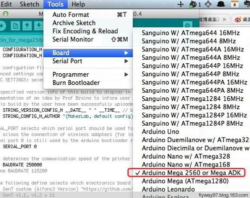
Software Setting Before uploading, driver should be installed for windows. Then choose the type of board: Tools > Board > Arduino Mega 2560 or Mega ADK. (Picture below)
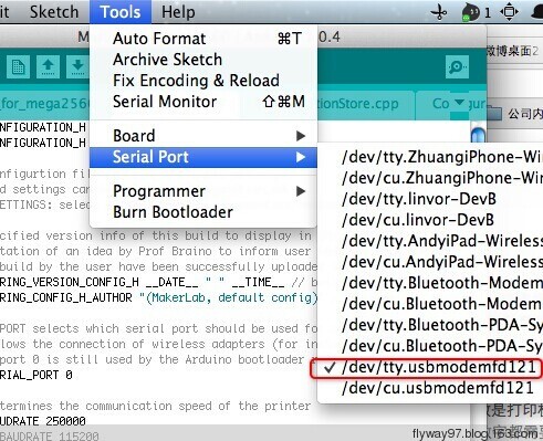
Select the serial port: Tools > Serial Port, the serial port for Rambo is usually the last one.
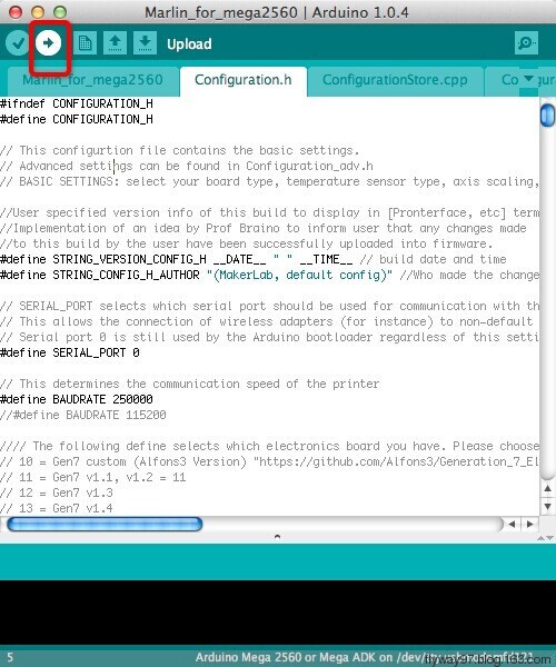
Click ![]() to check if there is any mistake. If not, click
to check if there is any mistake. If not, click ![]() to upload.
to upload.
During the process of uploading, the 3 LEDs corresponding to TX, RX and L on mega board will blink, if the blink stops, the uploading is done.
After the uploading, you can go on with the next step. If the uploading is unsuccessful, read the error report on IDE, figure out the problem, and then try again. Some frequent errors are: a wrong select of board type and serial port.
Get Started
Rambo is the CPU of a 3d printer, manipulating the whole process of printing which can’t be put in use directly without uploading firmware.
1. Firmware uploading- marlin.
2. Setting parameters of the firmware
3. The parameters that need setting are as below, for those not mentioned just leave them as default.
#define BAUDRATE 250000
This parameter is for the baud rate of serial port. Note: a successful communication can be realized only when the Baud rate of upper computer is identical with that of Firmware. The Baud rate is not set in random. The common Baud rate are: 2400,9600,19200,38400,57600,115200,250000. The last three are frequently used for 3D Printer.
- define MOTHERBOARD 701
This parameter is set for board type. 3D Printer has many types of main board, and the setting of IOs is different, therefore, the parameter has to correspond to the type of your board, or it can’t operate normally. For other board, you can refer to the annotation on the board.
 #define TEMP_SENSOR_0 3
 #define TEMP_SENSOR_BED 3
The two parameters are set for the type of temperature sensor respectively. They are the critical parameter to check if the sensor read temperature correctly. The printer can’t operate normally, even has potential risk (damage the device and even worse). You must modify depending on the temperature sensor you use.
#define EXTRUDE_MINTEMP 170
This parameter is set to avoid the potential risks when the extruder operates before reaching the rated temperature. If you use other 3D Printer, such as printer to make Chocolates, 45℃ is appropriate, so that the parameter configured to a lower value(such as 40℃).
 const bool X_ENDSTOPS_INVERTING = true;
 const bool Y_ENDSTOPS_INVERTING = true;
 const bool Z_ENDSTOPS_INVERTING = true.
The three parameters are set for the end stops of three axes. If the configuration is true, the end stop outputs 1 in default condition, and outputs 0 when triggered. That is to say, mechanical end stop should connect to the NO (normally open) contactor. If it is connected to the NC (normally closed), true should be changed to false.
 #define INVERT_X_DIR false
 #define INVERT_Y_DIR true
Mistakes are often made in the above two parameters. The parameters are different for different machinery. In principle, the origin should be at lower-left corner of the print platform (origin: [0, 0]), or at up-right corner (origin: [max, max]). Only in this way will the printing be correct, otherwise, the printing is the mirror image of one axis which is not what expected.
 #define X_HOME_DIR -1
 #define Y_HOME_DIR -1
 #define Z_HOME_DIR -1
If the position of the origin is the minimum, the parameter is -1; if it is the maximum, the parameter is 1.
 #define X_MAX_POS 205
 #define X_MIN_POS 0
 #define Y_MAX_POS 205
 #define Y_MIN_POS 0
 #define Z_MAX_POS 200
 #define Z_MIN_POS 0
These parameters are crucial to the printing size. Fill in parameters by reference to the coordinate graphs. It is important to note that the origin is not the printing center and the real printing center usually lies at [(x.max - x.min)/2, (y.max -y.min/2)]. The coordinate of central will be used in the slice tool. The printing center’s coordinate must correspond to the parameter configuration, or it will print to the outside of the platform.
#define HOMING_FEEDRATE {50*60, 50*60, 4*60, 0}
The parameter means the homing speeds (mm/min). This parameter can be set as default if you use the x-axis and y-axis adopt synchronous belt drive and z-axis adopts screw drive.
#define DEFAULT_AXIS_STEPS_PER_UNIT {85.3333, 85.3333, 2560, 158.8308}
These parameters are crucial to the printing size. These parameters indicate the pulse the axis need when operating 1mm. they are corresponding to x, y, z axis and extruder respectively. In most cases these figure should be calculated by yourself, you can refer to: http://calculator.josefprusa.cz/#steppers.
So far, the commonest parameters have been configured and the printer can work now. In addition, if the 2004 LCD needs verifying, you should delete the “//” from “//#define REPRAP_DISCOUNT_SMART_CONTROLLER” to ensure the normal working.
FAQS
1. I can’t upload program for Rambo using a USB.
Check if the external power supply for logic part is plugged in, or if the power supply is ok.
2. How many extruders does Rambo support?
Rambo supports at most 2 extruders.
3. What should I do if the driver installation failed?
You may encounter a problem “system cannot find the specific folder” in the process of driver installation when you use starter edition windows, because the starter edition of windows system has deleted some uncommon information for driver. The resolutions are as follows,
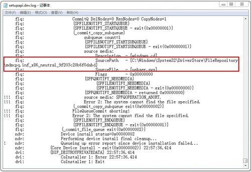
A: open C:\windows\inf\setupapi.dev.log
The file not only includes plug and play device, information for driver installation, but also record the reason of the failure of driver installation. Open this file and move to the end of the file you will observe the following information.
It is just the file error that causes the failure of Arduino driver installation.
B: creating a folder” mdmcpq.inf_x86_neutral_******** “in the path of
"C:\Windows\System32\DriverStore\FileRepository\ "
The identifications of all computers are different, so please refer to the prompt box from the “setupapi.dev.log” to know the “******* “. For example, information provided by my computer is
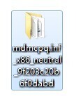
“C:\Windows\System32\DriverStore\FileRepository\mdmcpq.inf_x86_neutral_9f203c20b6f0dabd “
According to this prompt, I created another folder with the same name in the path of “C:\Windows\System32\DriverStore\FileRepository\”, as follows,
C: Download and decompress the following file and add it to the created folder mdmcpq.inf_x86_neutral_********.
32bits windows:
mdmcpq.inf_x86.rar Media:(http://www.arduino.cn/forum.php?mod=attachment&aid=MTIzMHw2ZjJkZDY1OXwxNDA0NzAyMDgxfDY0MDF8MjQ4NQ==)
64bits windows
mdmcpq.inf_amd64.rar [[Media:(http://www.arduino.cn/forum.php?mod=attachment&aid=MTIzMXxkN2QxMzdiMHwxNDA0NzAyMDgxfDY0MDF8MjQ4NQ%3D%3D) ]]
D. Reinstall driver step-by-step.
At this point, driver can be installed.
If the computer system is windows 8 and driver cannot be installed, there are some other alternative methods for you.
Click Windows and R
Input shutdown.exe /r /o /f /t 00
Click “ok”
The system enters “option” page automatically
Click FAQ
Click advanced options
Click windows boot settings
Click reboot button
The system will reboot and go to the advanced boot options
Click “disable driver and mandatory signature”
After the restart of the system, you can install the driver and the installation method is the same with that of windows 7.
Files
RAMBo-manual:
RAMBo silk:
File:Controller final reprapdiscount.PDF
Rambo family
Compared with the 1.1b version,Rambo 1.2G has the following updates: 1. Increased ESD (Electro-Static discharge) Electrostatic Discharge in the USB circuit section 2. The logical part of the circuit and MOSFET share the same power supply 3. enhanced anti-interference ability of signals.
