Difference between revisions of "A4988 Stepper Motor Driver Carrier Board"
| (7 intermediate revisions by the same user not shown) | |||
| Line 1: | Line 1: | ||
==Overview== | ==Overview== | ||
| + | [[File:A4988 carrier 1.jpg|300px]] | ||
| + | |||
This product is a carrier board or breakout board for Allegro’s A4988 DMOS Microstepping Driver with Translator and Overcurrent Protection. This stepper motor driver lets you control one bipolar stepper motor at up to 2 A output current per coil.This carrier has reverse power protection on the main power input and built-in 5 V and 3.3 V voltage regulators that eliminate the need for separate logic and motor supplies and let you control the driver with microcontrollers powered at 5 V or 3.3 V. | This product is a carrier board or breakout board for Allegro’s A4988 DMOS Microstepping Driver with Translator and Overcurrent Protection. This stepper motor driver lets you control one bipolar stepper motor at up to 2 A output current per coil.This carrier has reverse power protection on the main power input and built-in 5 V and 3.3 V voltage regulators that eliminate the need for separate logic and motor supplies and let you control the driver with microcontrollers powered at 5 V or 3.3 V. | ||
| Line 14: | Line 16: | ||
==Usage== | ==Usage== | ||
===Connections=== | ===Connections=== | ||
| + | [[File:A4988 carrier 2.jpg]] | ||
The driver requires a logic supply voltage (3 – 5.5 V) to be connected across the VDD and GND pins and a motor supply voltage (8 – 30 V) to be connected across VMOT and GND. The logic voltage can be supplied from an external source, such as that powering the logic of the rest of the system, or by jumpering the output of the 5 V or 3.3 V voltage regulator outputs to VDD. | The driver requires a logic supply voltage (3 – 5.5 V) to be connected across the VDD and GND pins and a motor supply voltage (8 – 30 V) to be connected across VMOT and GND. The logic voltage can be supplied from an external source, such as that powering the logic of the rest of the system, or by jumpering the output of the 5 V or 3.3 V voltage regulator outputs to VDD. | ||
| Line 30: | Line 33: | ||
Another way to set the current limit is to measure the voltage on the REF pin and to calculate the resulting current limit. The current limit relates to the reference voltage as follows: | Another way to set the current limit is to measure the voltage on the REF pin and to calculate the resulting current limit. The current limit relates to the reference voltage as follows: | ||
| − | To calculate the current, A = VREF / (8 * | + | To calculate the current, A = VREF / (8 * 0.1) |
==Document== | ==Document== | ||
[http://www.geeetech.com/Documents/A4988-Datasheet.pdf A4988 datasheet] | [http://www.geeetech.com/Documents/A4988-Datasheet.pdf A4988 datasheet] | ||
| + | [http://www.geeetech.com/Documents/A4988%20carrier%20Schematic%20.rar A4988 carrier schematic] | ||
==Arduino Example Code== | ==Arduino Example Code== | ||
| Line 61: | Line 65: | ||
==How to buy== | ==How to buy== | ||
| − | Click here to buy [http://www.geeetech.com/stepstick-a4988- | + | Click here to buy [http://www.geeetech.com/stepstick-a4988-reprap-motor-driver-with-voltage-regulators-p-629.html A4988 Reprap Motor Driver with Voltage Regulators] |
Latest revision as of 03:21, 18 March 2013
Contents
Overview
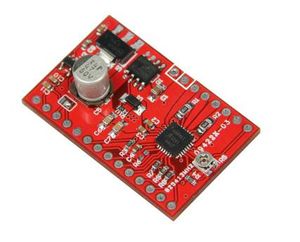
This product is a carrier board or breakout board for Allegro’s A4988 DMOS Microstepping Driver with Translator and Overcurrent Protection. This stepper motor driver lets you control one bipolar stepper motor at up to 2 A output current per coil.This carrier has reverse power protection on the main power input and built-in 5 V and 3.3 V voltage regulators that eliminate the need for separate logic and motor supplies and let you control the driver with microcontrollers powered at 5 V or 3.3 V.
Features
- Simple step and direction control interface
- Five different step resolutions: full-step, half-step, quarter-step, eighth-step, and sixteenth-step
- Adjustable current control lets you set the maximum current output with a potentiometer, which lets you use voltages above your stepper motor’s rated voltage to achieve higher step rates
- Intelligent chopping control that automatically selects the correct current decay mode (fast decay or slow decay)
- Over-temperature thermal shutdown, under-voltage lockout, and crossover-current protection
- Short-to-ground and shorted-load protection
Usage
Connections
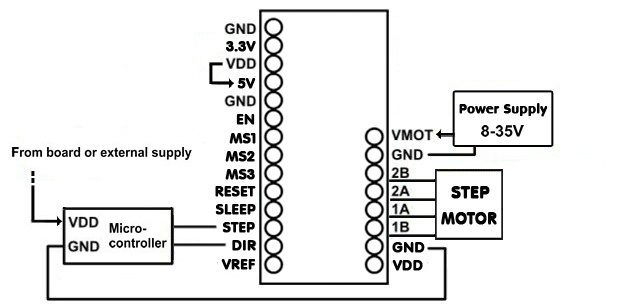
The driver requires a logic supply voltage (3 – 5.5 V) to be connected across the VDD and GND pins and a motor supply voltage (8 – 30 V) to be connected across VMOT and GND. The logic voltage can be supplied from an external source, such as that powering the logic of the rest of the system, or by jumpering the output of the 5 V or 3.3 V voltage regulator outputs to VDD.
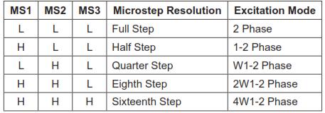
Stepper motors typically have a step size specification (e.g. 1.8° or 200 steps per revolution), which applies to full steps. A microstepping driver such as the A4988 allows higher resolutions by allowing intermediate step locations, which are achieved by energizing the coils with intermediate current levels. For instance, driving a motor in quarter-step mode will give the 200-step-per-revolution motor 800 microsteps per revolution by using four different current levels.
The resolution (step size) selector inputs (MS1, MS2, MS3) enable selection from the five step resolutions according to the table below.
Control inputs
Each pulse to the STEP input corresponds to one microstep of the stepper motor in the direction selected by the DIR pin. Note that the STEP and DIR pins are not pulled to any particular voltage internally, so you should not leave either of these pins floating in your application. If you just want rotation in a single direction, you can tie DIR directly to VCC or GND. The chip has three different inputs for controlling its many power states: RST, SLP, and EN. For details about these power states, see the datasheet.
Current limiting
The A4988 supports such active current limiting, and the trimmer potentiometer on the board can be used to set the current limit. One way to set the current limit is to put the driver into full-step mode and to measure the current running through a single motor coil without clocking the STEP input. The measured current will be 0.7 times the current limit (since both coils are always on and limited to 70% of the current limit setting in full-step mode).
Another way to set the current limit is to measure the voltage on the REF pin and to calculate the resulting current limit. The current limit relates to the reference voltage as follows: To calculate the current, A = VREF / (8 * 0.1)
Document
Arduino Example Code
int dirPin = 8;
int stepperPin = 7;
void setup() {
 pinMode(dirPin, OUTPUT);
 pinMode(stepperPin, OUTPUT);
}
 void step(boolean dir,int steps){
 digitalWrite(dirPin,dir);
 delay(50);
 for(int i=0;i<steps;i++){
   digitalWrite(stepperPin, HIGH);
   delayMicroseconds(800);
   digitalWrite(stepperPin, LOW);
   delayMicroseconds(800);
 }
}
void loop(){
 step(true,1600);
 delay(500);
 step(false,1600*5);
 delay(500);
}
How to buy
Click here to buy A4988 Reprap Motor Driver with Voltage Regulators


