Difference between revisions of "Serial Blutooth Module & Bluetooth Bee"
(→How to buy) |
|||
| (17 intermediate revisions by the same user not shown) | |||
| Line 1: | Line 1: | ||
==Overview== | ==Overview== | ||
| − | [[File:Serial | + | [[File:Serial BT1.jpg|300px]] |
| − | The | + | [[File:BT bee1.jpg|300px]] |
| + | |||
| + | The serial bluetooth module is an easy to use module for transparent wireless serial connection setup. Serial port Bluetooth module is fully qualified Bluetooth V2.1+EDR(Enhanced Data Rate) 3Mbps Modulation with complete 2.4GHz radio transceiver and baseband. It uses CSR Bluecore 04-External single chip Bluetooth system with CMOS technology and AFH(Adaptive Frequency Hopping Feature). Hope it will simplify your overall design/development cycle. | ||
==Specifications:== | ==Specifications:== | ||
| Line 27: | Line 29: | ||
==Application Circuit of Bluetooth module on-board== | ==Application Circuit of Bluetooth module on-board== | ||
| + | [[File:Bt application.jpg|400px]] | ||
==Master/slave mode setting and other configuration:== | ==Master/slave mode setting and other configuration:== | ||
| Line 36: | Line 39: | ||
PIO(5)——master-slave mode setting interface by hardware. 3.3V high level for master mode, GND(or impending) for slave mode. <br> | PIO(5)——master-slave mode setting interface by hardware. 3.3V high level for master mode, GND(or impending) for slave mode. <br> | ||
| − | |||
| − | The PIO(4) on the | + | [[File:Serial BT1.jpg|300px]] |
| + | |||
| + | ;The PIO(4) on the serial bluetooth module has been connected to High level (3.3V) for hardware setting. So toggling the switch on the board to ‘M’ end set the module to the master mode, ‘S’ is for slave mode. | ||
| − | + | [[File:BT bee1.jpg|300px]] | |
| − | |||
| + | ;The PIO(4) on the Bluetooth Bee module is impening for software setting. Use the AT command AT+role for setting maste/slave mode. | ||
| + | ===State instructions LED=== | ||
| + | [[File:BT LED.jpg|500px]] | ||
==Example== | ==Example== | ||
| − | The Bluetooth module as the master is connected to a USB to ttl | + | The Bluetooth module as the master is connected to a USB to ttl converter, the Bluetooth bee as the slave module is stacked on the Bee socket on the V5 expansion shield. The computer send a character ‘a’ via usb to ttl module . After the Arduino have received it via wireless serial communication, it will flash the led on-board and send back a string ‘geeetech’. |
| + | |||
| + | [[File:BT connecion.jpg]] | ||
| + | [[File:Bt serial port.jpg|500px]] | ||
| Line 69: | Line 78: | ||
} | } | ||
} | } | ||
| − | |||
==Document== | ==Document== | ||
| − | [Bluetooth | + | [http://www.geeetech.com/Documents/Wireless%20Bluetooth%20%20BC04-User%20M.rar Wireless Bluetooth BC04-User Manual] |
| − | |||
==How to buy== | ==How to buy== | ||
| − | Click here to buy | + | Click here to buy [http://www.geeetech.com/btbee-bluetooth-to-serial-port-module-p-599.html Bluetooth Bee] |
Latest revision as of 06:01, 17 September 2012
Contents
Overview
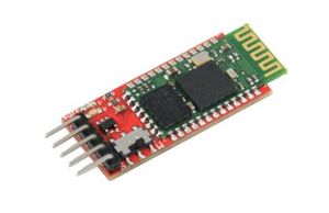
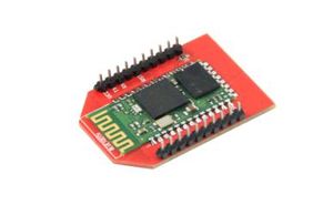
The serial bluetooth module is an easy to use module for transparent wireless serial connection setup. Serial port Bluetooth module is fully qualified Bluetooth V2.1+EDR(Enhanced Data Rate) 3Mbps Modulation with complete 2.4GHz radio transceiver and baseband. It uses CSR Bluecore 04-External single chip Bluetooth system with CMOS technology and AFH(Adaptive Frequency Hopping Feature). Hope it will simplify your overall design/development cycle.
Specifications:
- Bluetooth protocol: Bluetooth Specification v2.1 + EDR
- USB protocol: USB v1.1/2.0
- Frequency: 2.4GHz ISM band
- Modulation: GFSK (Gaussian Frequency Shift Keying)
- Transmit power: ≤ 4dBm, Class 2
- Sensitivity: ≤-84dBm at 0.1% BER
- Rate: 2.1Mbps(Max)/160 kbps(Asynchronous);1Mbps/1Mbps(Synchronous)
- security features: Authentication and encryption
- Support profiles: Bluetooth serial port (master & slave)
- Power Supply: +3.3 VDC 50mA
- Operating temperature: -20 ~ +55 Centigrade
Features
- Support bluetooth standard v2.1 + EDR.
- Supports soft/hardware for master/slave mode setting.
- Through the AT command, yon can set the control parameters of the module and issue orders to the module.
- Working state instructions.
- Suitable for embedded serial transmission wireless alternative.
- On-board efficient antenna.
- Support connecting seven slave equipment.
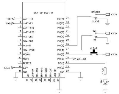
Application Circuit of Bluetooth module on-board
Master/slave mode setting and other configuration:
master/slave mode setting
The bluetooth module on-board supports setting the master/slave mode by soft or hardware. The method is as follows:
PIO(4)——soft/hardware setting: Low level(or impending) for hardware setting master-slave mode. High level(3.3V)for soft setting master-slave mode.
PIO(5)——master-slave mode setting interface by hardware. 3.3V high level for master mode, GND(or impending) for slave mode.
- The PIO(4) on the serial bluetooth module has been connected to High level (3.3V) for hardware setting. So toggling the switch on the board to ‘M’ end set the module to the master mode, ‘S’ is for slave mode.
- The PIO(4) on the Bluetooth Bee module is impening for software setting. Use the AT command AT+role for setting maste/slave mode.
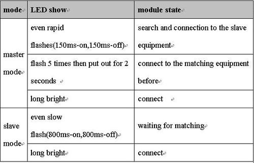
State instructions LED
Example
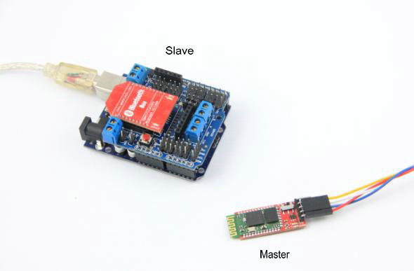
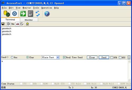
The Bluetooth module as the master is connected to a USB to ttl converter, the Bluetooth bee as the slave module is stacked on the Bee socket on the V5 expansion shield. The computer send a character ‘a’ via usb to ttl module . After the Arduino have received it via wireless serial communication, it will flash the led on-board and send back a string ‘geeetech’.
int val;
int ledpin=13;
void setup()
{
 Serial.begin(9600);
 pinMode(ledpin,OUTPUT);
}
void loop()
{
 val=Serial.read();
 if(val=='a')
 {
   digitalWrite(ledpin,HIGH);
   delay(250);
   digitalWrite(ledpin,LOW);
   delay(250);
   Serial.println("geeetech");
 }
}
Document
Wireless Bluetooth BC04-User Manual
How to buy
Click here to buy Bluetooth Bee
