Difference between revisions of "StepStick A4988 Stepper Driver Module"
(→Overview) |
|||
| (7 intermediate revisions by the same user not shown) | |||
| Line 14: | Line 14: | ||
*Short-to-ground and shorted-load protection | *Short-to-ground and shorted-load protection | ||
| + | ==Document== | ||
| + | [http://www.geeetech.com/Documents/A4988-Datasheet.pdf A4988 datasheet] | ||
==Usage== | ==Usage== | ||
| − | [[File:A4988 5.jpg]] | + | [[File:A4988 5.jpg|750px]] |
The driver requires a logic supply voltage (3 – 5.5 V) to be connected across the VDD and GND pins and a motor supply voltage of (8 – 35 V) to be connected across VMOT and GND. These supplies should have appropriate decoupling capacitors close to the board, and they should be capable of delivering the expected currents (peaks up to 4 A for the motor supply). | The driver requires a logic supply voltage (3 – 5.5 V) to be connected across the VDD and GND pins and a motor supply voltage of (8 – 35 V) to be connected across VMOT and GND. These supplies should have appropriate decoupling capacitors close to the board, and they should be capable of delivering the expected currents (peaks up to 4 A for the motor supply). | ||
| Line 29: | Line 31: | ||
;Connecting or disconnecting a stepper motor while the driver is powered can destroy the driver. (More generally, rewiring anything while it is powered is asking for trouble.) | ;Connecting or disconnecting a stepper motor while the driver is powered can destroy the driver. (More generally, rewiring anything while it is powered is asking for trouble.) | ||
| − | [[File:A4988 2.jpg]] | + | [[File:A4988 2.jpg|600px]] |
==Example code== | ==Example code== | ||
| Line 38: | Line 40: | ||
pinMode(stepperPin, OUTPUT); | pinMode(stepperPin, OUTPUT); | ||
} | } | ||
| − | |||
void step(boolean dir,int steps){ | void step(boolean dir,int steps){ | ||
digitalWrite(dirPin,dir); | digitalWrite(dirPin,dir); | ||
| Line 55: | Line 56: | ||
delay(500); | delay(500); | ||
} | } | ||
| + | |||
==How to buy== | ==How to buy== | ||
| − | Click here to buy A4988 Stepper Driver Module | + | Click here to buy [http://www.geeetech.com/stepstick-a4988-stepper-driver-module-pololu-p-577.html A4988 Stepper Driver Module] |
Latest revision as of 08:19, 2 August 2012
Overview
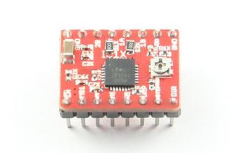
This product is a breakout board for Allegro’s A4988 DMOS Microstepping Driver with Translator and Overcurrent Protection; please read the A4988 datasheet carefully before using this product. This stepper motor driver lets you to operate bipolar stepper motors in full-, half-, quarter-, eighth-, and sixteenth-step modes, with an output drive capacity of up to 35 V and 2 A.
The translator is the key to the easy implementation of the A4988. Simply inputting one pulse on the STEP input drives the motor one microstep. There are no phase sequence tables, high frequency control lines, or complex interfaces to program.The A4988 interface is an ideal fit for applications where a complex microprocessor is unavailable or is overburdened.
Features
- Simple step and direction control interface
- Five different step resolutions: full-step, half-step, quarter-step, eighth-step, and sixteenth-step
- Adjustable current control lets you set the maximum current output with a potentiometer, which lets you use voltages above your stepper motor’s rated voltage to achieve higher step rates
- Intelligent chopping control that automatically selects the correct current decay mode (fast decay or slow decay)
- Over-temperature thermal shutdown, under-voltage lockout, and crossover-current protection
- Short-to-ground and shorted-load protection
Document
Usage
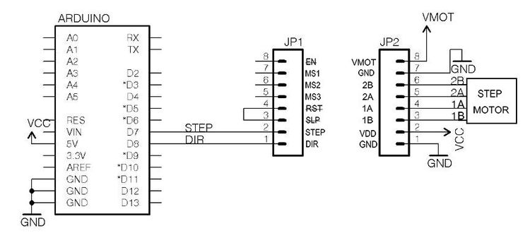
The driver requires a logic supply voltage (3 – 5.5 V) to be connected across the VDD and GND pins and a motor supply voltage of (8 – 35 V) to be connected across VMOT and GND. These supplies should have appropriate decoupling capacitors close to the board, and they should be capable of delivering the expected currents (peaks up to 4 A for the motor supply).
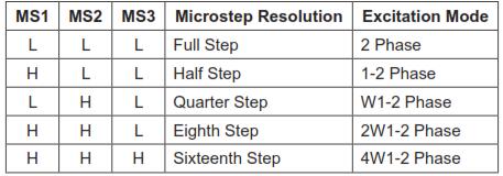
Stepper motors typically have a step size specification (e.g. 1.8° or 200 steps per revolution), which applies to full steps. A microstepping driver such as the A4988 allows higher resolutions by allowing intermediate step locations, which are achieved by energizing the coils with intermediate current levels. For instance, driving a motor in quarter-step mode will give the 200-step-per-revolution motor 800 microsteps per revolution by using four different current levels.
The resolution (step size) selector inputs (MS1, MS2, MS3) enable selection from the five step resolutions according to the table below.
- Warning
- Connecting or disconnecting a stepper motor while the driver is powered can destroy the driver. (More generally, rewiring anything while it is powered is asking for trouble.)
Example code
int dirPin = 8;
int stepperPin = 7;
void setup() {
 pinMode(dirPin, OUTPUT);
 pinMode(stepperPin, OUTPUT);
}
 void step(boolean dir,int steps){
 digitalWrite(dirPin,dir);
 delay(50);
 for(int i=0;i<steps;i++){
   digitalWrite(stepperPin, HIGH);
   delayMicroseconds(800);
   digitalWrite(stepperPin, LOW);
   delayMicroseconds(800);
 }
}
void loop(){
 step(true,1600);
 delay(500);
 step(false,1600*5);
 delay(500);
}
How to buy
Click here to buy A4988 Stepper Driver Module


