Difference between revisions of "JCX-M6 Flight Controller PV Fixed"
| (14 intermediate revisions by the same user not shown) | |||
| Line 1: | Line 1: | ||
| + | ==Introduction== | ||
| + | |||
[[File:XM-6-1.jpg|500px]] | [[File:XM-6-1.jpg|500px]] | ||
| Line 23: | Line 25: | ||
==Functions== | ==Functions== | ||
===Stable flight=== | ===Stable flight=== | ||
| − | + | In enhanced-stability mode, the gyroscope automatically adjusts to compensate for fixed wings, elevators, and rudders. This enhances wind-resistance capability and reduces speed failure to allow for stable flight. 3D flights such as inverted flight, slanting flight, and hanging flight become easy and do not compromise the controllability of airplanes. Flight becomes so easy for us. | |
===Stunt flight assistance=== | ===Stunt flight assistance=== | ||
| − | + | 1. Stunt flight modes, besides facilitating stability of flight, feature the flight locked function by high-precision digital gyro automatically locking the channels of Aileron, Elevator, and Rudder. This function makes inverted flight, slanting flight, hanging flight, and even 360-degree rotation available without compromise which indicates a more accurate flight control with flexibility at the same time. Takeoff and landing become quite easy, if without considering center of gravity had adjust, the difficult flight's plane also will be easy to control. More information will be demonstrated in the 8th item of Notice for the first use. <br> | |
| − | |||
| − | |||
| − | + | 2. Independent gyro gain adjustment potentiometer and the algorithm of software gyro gain make the gyro into its best automatically.<br> | |
| − | + | 3. 4-digit DIP switcher makes the functional settings for M6 board become easy and convenient.<br> | |
| − | + | 4. Controlling switcher of flight manual is used through the channel of on-and-off on the remote control to control the start function. When at high altitudes, flight manual control is able to be achieved by this switch so that you can feel the flight functions of plane whether it is controlled or not, practice flight control in none-flight manual mode, and improve your skills easily.<br> | |
| − | + | 5. Red and blue LED lights make it easier to tell the work mode and the status.<br> | |
| − | + | 6. Its small size of 30x42mm, the weight of 6g, and perfect configuration make it easily to be installed and used in any size of planes. <br> | |
| + | 7. It is supportive to various types of fixed-wing, flying-wing, and V-tail.<br> | ||
==Flight Manual LED Introduction== | ==Flight Manual LED Introduction== | ||
| − | Procedures for Power-on: Red and blue lights->on for 1s->off for 1s->on for 5s->blue light flickers for about 3s (The gyro is locked now and please assure that the plane stays in rest)->Red and blue lights make different indications according to the intrinsic parameters. | + | 1. Procedures for Power-on: Red and blue lights->on for 1s->off for 1s->on for 5s->blue light flickers for about 3s (The gyro is locked now and please assure that the plane stays in rest)->Red and blue lights make different indications according to the intrinsic parameters. |
| − | + | 2. Remote control switcher indicator: The red light on means that the remote control switcher on (If it's in the flight control mode, at this time, spin the plane and in theory, the correction rudder output of the gyroscope about aileron, elevator and rudder will appear.), off or twinkle means off. | |
| − | + | 3. Supportive aircraft type directives in flight control mode: Blue light, with 500ms a flicker, indicates the aircraft in the fixed-wing mode; with 1s a faster flicker, in flying-wing mode; with 1s a flicker, in V-tail mode. Red light, with a 1s flash in 5s, indicates that the aircraft is in trick mode; with just a flicker per second, in entire open mode. | |
| − | + | 4. Flight manual parameter settings: After switching on the DIP settings (starting after switching off all), blue light off and red light on indicates waiting; blue light on and red light off indicates in progress; red light quickly flickers within a long time indicates that the DIP switchers should be all turned off. | |
| − | + | 5. Observe the LED lights after starting for comprehending the flight control working modes: | |
[[File:XM-6-3.jpg]] | [[File:XM-6-3.jpg]] | ||
| Line 95: | Line 96: | ||
When the switches are set to the preceding status, the flight controller is in flight status. Then you can set the flight controller according to the flight controller DIP switch function settings and tell the difference according to the LED indicators. <br> | When the switches are set to the preceding status, the flight controller is in flight status. Then you can set the flight controller according to the flight controller DIP switch function settings and tell the difference according to the LED indicators. <br> | ||
| − | [[File:XM image5.png]] | + | [[File:XM image5.png|880px]] |
; Selecting an airplane type before configuring parameters | ; Selecting an airplane type before configuring parameters | ||
| Line 115: | Line 116: | ||
#Set all switches to OFF. | #Set all switches to OFF. | ||
| − | [[File:XM image7.png]] | + | [[File:XM image7.png|880px]] |
; Controller signal output setting (fixed wing, elevator, and rudder corresponding to 2, 3, and 4) | ; Controller signal output setting (fixed wing, elevator, and rudder corresponding to 2, 3, and 4) | ||
| Line 142: | Line 143: | ||
==Notice for The First Use== | ==Notice for The First Use== | ||
| − | + | 1. Please carefully check the connecting directions of each channel, make sure that the remote control switcher stays OFF, and the DIP switcher is already set in correct position according to the Flight manual DIP switcher settings. If you want to set the parameters of flight manual, eg. Gyro signal, remote control signal, please switch off all of them and reset the parameters based on Flight manual parameters setting via DIP switcher. | |
| − | |||
| − | + | 2. Please place the plane in steady in order to keep it from shaking and to insure that the gyro is locked successfully. The plane should remain still when the gyro is locking, even the shaking situation caused by wind is not allowed; if the wind remains strong, the best way is to reverse the plane and placing it onto stable and secure place. There are two methods to check if the gyro has been locked successfully: 1. If the blue LED light stops flickering; 2. Control any channel of aileron, elevator, or rudder via remote controller; the plane would have respectively responded to each channel if succeed. | |
| − | + | 3. Check the remote control to insure it is in work. After repeatedly switching the remote controller, if the red LED light on the flight manual appears long-time on or off, it means that the channels are connected. (Caution: There may be a 1s quick twinkle at the moment of 5s, which indicates that the flight manual stays in special flight that you don' t have to worry about.) Long-time on means the switch is on; if your remote controller is lack of this channel, please set the flight manual into the full-flight open mode according to Flight manual DIP switcher settings. Red LED light will flicker once for 1s to indicate that the plane is now in the mode of full-flight open. | |
| − | + | 4. Check the LED indication. Please check the red and blue LED lights based on the Flight Manual LED Introduction, understand the working mode that the flight manual is now in and if the current mode is what you want; if not, please reset the parameters into the mode you want according to the Flight manual DIP switcher settings. | |
| − | + | 5. Check the signal output of remote control. First, check if the aileron, elevator, and rudder are correct by remote control. There are two methods to moderate if incorrect: 1. Set the output direction of intrinsic channel of remote control; 2. Set the mode according to Picture 3 & 7 of Flight Manual Parameters settings until each control of the responding channel is perfectly correct. | |
| − | + | 6. Check the signal output of gyro amendment. Please carefully check out if the output of each channel is perfectly correct based on the introduction of Gyro Gain Adjustment. If it is incorrect, please correct it according to Picture 2 & 6 of Flight Manual Parameters settings until it is perfectly correct. | |
| − | + | 7. Flying-wing (Delta-wing) should be mixed controlled by aileron and elevator; V-tail wing should be mixed controlled by elevator and rudder. Remote control should not be set into mixed mode, which should be completed by M6 flight control board. | |
| − | + | 8. Stunt flight locked mode. When the remote control return back to middle position, the flight manual will automatically lock the current flight mode in order to assure that three axial directions are in their positions ( it is natural that the angle of the axis may be in a little bit deviation caused by vibration, inaccuracy, and the properties of gyro, etc.) A compensation rudder volume will be output automatically after the deviation; thus, you will find kind of quiet deviations in aileron, elevator, and rudder. The deviation of axial angle, resulting from holding the plane in hand, is the auto-output compensation rudder of flight manual, which has to be returned back to the middle before takeoff. If there occurs deviation, please follow the 4 resolutions: <br> | |
(a) Close down the channel of remote control switcher so that each channel steering gear will return automatically. <br> | (a) Close down the channel of remote control switcher so that each channel steering gear will return automatically. <br> | ||
(b) Close down the channel of remote control before taking off, and then turn it on after the plane has taken off. <br> | (b) Close down the channel of remote control before taking off, and then turn it on after the plane has taken off. <br> | ||
| Line 163: | Line 163: | ||
(d) Place the aircraft on the ground so that the flight manual will detect that the aircraft is static and then make it back to middle. 4 seconds later, the gyroscope will restart. If there is no remote control switcher, use (c) and (d) to settle the problem. Note that when you are using the flight manual for the first time, please try it for several times. Make sure that you have already comprehended the way of using flight manual and then fly the aircraft. <br> | (d) Place the aircraft on the ground so that the flight manual will detect that the aircraft is static and then make it back to middle. 4 seconds later, the gyroscope will restart. If there is no remote control switcher, use (c) and (d) to settle the problem. Note that when you are using the flight manual for the first time, please try it for several times. Make sure that you have already comprehended the way of using flight manual and then fly the aircraft. <br> | ||
| − | + | 9. Sensitivity adjustment. The sensitivity is to adjust the control strength of the gyroscope on the airplane. The higher degree the gyroscope turns clock wisely, the greater the sensitivity. Usually, you are advised to adjust the sensitivity to 1/2 or 1/3 and then adjust it slightly as required. If you feel the airplane jitters greatly, adjust the sensitivity potentiometer counterclockwise slightly. Or adjust the sensitivity potentiometer clock wisely greatly to obtain optimal performance. | |
| + | |||
| + | ==How to buy== | ||
| + | Click here to buy [http://www.geeetech.com/jcxm6-flight-controller-pv-fixed-p-542.html JCX-M6 Flight Controller PV Fixed] | ||
Latest revision as of 09:37, 19 June 2012
Contents
Introduction
Thank you for using JCX-M6. JCX-M6 is a flight controller especially designed for fixed-wing airplanes. It can perform calculation for flying wings, elevators, and rudders and output compensation rudder volume for channels in real time to facilitate stability of airplanes during flight. JCX-M6 features special flight assistance function which can help control flight modes. Inverted flight, slanting flight, and hanging flight are available without compromise. Under a fourth or fifth wind force, airplane KT330 can still have inverted flight, slanting flight, and hanging flight. With proper power and driving force, wind is not a problem now. fixed wings, flying wings (triangular wings), and V-tails (aero-engine airplanes, CESSNA, and 3D devices) are supported. Before using JCX-M6, please read this user manual carefully.
Packaging list
- One flight control board
- Four flight control connection wires
- One double-sided tape and one magic tape
- One flat head screwdriver for sensitivity adjustment
- One instruction card
- One detailed user manual
Technical Specifications
- Dimension: 30 x 42 mm
- Weight: 6 g
- Voltage: 4-9 V DC
- Current: 40 MA(max)
- Sample Rate of Gyro: 2 KHz
- PWM Input: 5 0Hz PMW
- PMW Output: 50 Hz PMW
- Operating temperature: -25℃ to 80℃
Functions
Stable flight
In enhanced-stability mode, the gyroscope automatically adjusts to compensate for fixed wings, elevators, and rudders. This enhances wind-resistance capability and reduces speed failure to allow for stable flight. 3D flights such as inverted flight, slanting flight, and hanging flight become easy and do not compromise the controllability of airplanes. Flight becomes so easy for us.
Stunt flight assistance
1. Stunt flight modes, besides facilitating stability of flight, feature the flight locked function by high-precision digital gyro automatically locking the channels of Aileron, Elevator, and Rudder. This function makes inverted flight, slanting flight, hanging flight, and even 360-degree rotation available without compromise which indicates a more accurate flight control with flexibility at the same time. Takeoff and landing become quite easy, if without considering center of gravity had adjust, the difficult flight's plane also will be easy to control. More information will be demonstrated in the 8th item of Notice for the first use.
2. Independent gyro gain adjustment potentiometer and the algorithm of software gyro gain make the gyro into its best automatically.
3. 4-digit DIP switcher makes the functional settings for M6 board become easy and convenient.
4. Controlling switcher of flight manual is used through the channel of on-and-off on the remote control to control the start function. When at high altitudes, flight manual control is able to be achieved by this switch so that you can feel the flight functions of plane whether it is controlled or not, practice flight control in none-flight manual mode, and improve your skills easily.
5. Red and blue LED lights make it easier to tell the work mode and the status.
6. Its small size of 30x42mm, the weight of 6g, and perfect configuration make it easily to be installed and used in any size of planes.
7. It is supportive to various types of fixed-wing, flying-wing, and V-tail.
Flight Manual LED Introduction
1. Procedures for Power-on: Red and blue lights->on for 1s->off for 1s->on for 5s->blue light flickers for about 3s (The gyro is locked now and please assure that the plane stays in rest)->Red and blue lights make different indications according to the intrinsic parameters.
2. Remote control switcher indicator: The red light on means that the remote control switcher on (If it's in the flight control mode, at this time, spin the plane and in theory, the correction rudder output of the gyroscope about aileron, elevator and rudder will appear.), off or twinkle means off.
3. Supportive aircraft type directives in flight control mode: Blue light, with 500ms a flicker, indicates the aircraft in the fixed-wing mode; with 1s a faster flicker, in flying-wing mode; with 1s a flicker, in V-tail mode. Red light, with a 1s flash in 5s, indicates that the aircraft is in trick mode; with just a flicker per second, in entire open mode.
4. Flight manual parameter settings: After switching on the DIP settings (starting after switching off all), blue light off and red light on indicates waiting; blue light on and red light off indicates in progress; red light quickly flickers within a long time indicates that the DIP switchers should be all turned off.
5. Observe the LED lights after starting for comprehending the flight control working modes:
(Caution: Blue and red LED light independently indicates each mode; if it is used for the first time, please repeatedly set different working modes of flight manual via DIP switcher in order to grasp and be familiar with the indications of LED lights.)
Flight manual DIP switcher settings
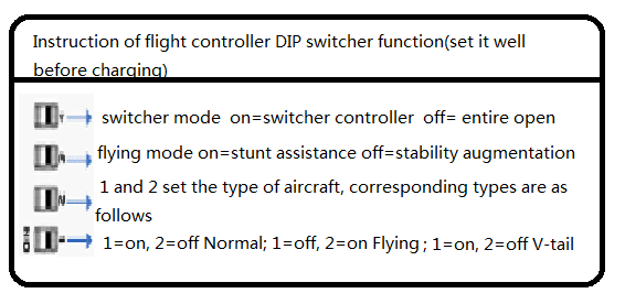
Before starting, please set the corresponding switching function with the direction of the picture below. Also, the modes can be freely altered after starting. The flight controller will read the status of the DIP switcher real-time and output them with different flash types combined by red light and blue light. After matching the corresponding types and function and checking all the channels unmistakably, the aircraft can fly.
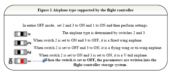
- Airplane type supported by the flight controller
In entire OFF mode, set 2 and 3 to ON and 1 to ON and then perform settings.
The airplane type is determined by switches 2 and 3.
When switch 2 is set to ON and 3 to OFF, it is a fixed wing airplane.
When switch 2 is set to OFF and 3 to ON, it is a flying wing or tri-wing airplane.
When switch 2 is set to ON and 3 is set to ON, it is a V-tail airplane.
When the switch is set to OFF, the parameters are written into the flight controller storage system.
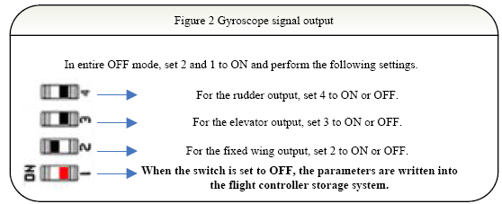
- Gyroscope signal output
In entire OFF mode, set 2 and 1 to ON and perform the following settings.
For the rudder output, set 4 to ON or OFF.
For the elevator output, set 3 to ON or OFF.
For the fixed wing output, set 2 to ON or OFF.
- When the switch is set to OFF, the parameters are written into the flight controller storage system.
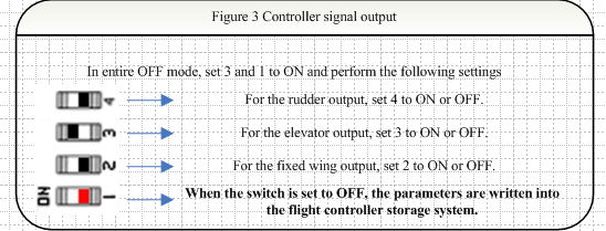
- Controller signal output
In entire OFF mode, set 3 and 1 to ON and perform the following settings
For the rudder output, set 4 to ON or OFF.
For the elevator output, set 3 to ON or OFF.
For the fixed wing output, set 2 to ON or OFF.
- When the switch is set to OFF, the parameters are written into the flight controller storage system.
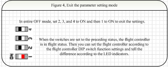
- Exit the parameter setting mode
In entire OFF mode, set 2, 3, and 4 to ON and then 1 to ON to exit the settings.
When the switches are set to the preceding status, the flight controller is in flight status. Then you can set the flight controller according to the flight controller DIP switch function settings and tell the difference according to the LED indicators.
- Selecting an airplane type before configuring parameters
- Set all switches to OFF and then power on.
- Set 2 and 3 to ON and 1 and 4 to OFF.
- Set 1 to ON.
- Set 2 and 3 and select an airplane type.
- Set 1 to OFF. The parameters are stored.
- Set all switches to OFF.
- Gyroscope output setting (fixed wing, elevator, and rudder corresponding to 2, 3, and 4)
- Set all switches to OFF and then power on.
- Set 2 to ON and 1, 3, and 4 to OFF.
- Set 1 to ON.
- Flip the related switch and rotate the airplane to check the correct output.
- Set 1 to OFF. The parameters are stored.
- Set all switches to OFF.
- Controller signal output setting (fixed wing, elevator, and rudder corresponding to 2, 3, and 4)
- Set all switches to OFF and then power on.
- Set 3 to ON, and 1, 3, and 4 to OFF.
- Set 1 to ON.
- Flip the channel related to the controller and check the correct output.
- Set 1 to OFF. The parameters are stored.
- Set all switches to OFF.
Gyroscope calibration
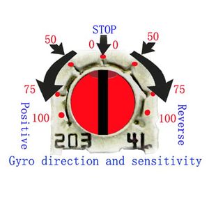
The direction and the sensitivity settings of gyroscope is below, spin the sensitivity pot clockwise or anticlockwise from stop position, the sensitivity is in proportion to the pot spinning. Positive spinning output positive signal, reverse spinning output positive signal. Please note the reference position of the sensitivity.
Installation and Wiring
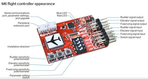
- The M6 board can be mounted on both sides (top or bottom) of plane. The label of plane on the M6 board should be in perfect paralleled and matched with the plane; it'll be better to be in the center of the fuselage. Please stably stick it on the plane with double sided tape to insure it is flat, steady, and secure. It will be in big trouble, if inappropriate or loosened.
- iSW-iAIL-iELE-iRUD should be respectively matched to the channel of switcher, aileron, elevator, and rudder of remote receiver; oAIL-oELE-oRUD should be respectively matched to the servo of aileron, elevator, and rudder.
Notice for The First Use
1. Please carefully check the connecting directions of each channel, make sure that the remote control switcher stays OFF, and the DIP switcher is already set in correct position according to the Flight manual DIP switcher settings. If you want to set the parameters of flight manual, eg. Gyro signal, remote control signal, please switch off all of them and reset the parameters based on Flight manual parameters setting via DIP switcher.
2. Please place the plane in steady in order to keep it from shaking and to insure that the gyro is locked successfully. The plane should remain still when the gyro is locking, even the shaking situation caused by wind is not allowed; if the wind remains strong, the best way is to reverse the plane and placing it onto stable and secure place. There are two methods to check if the gyro has been locked successfully: 1. If the blue LED light stops flickering; 2. Control any channel of aileron, elevator, or rudder via remote controller; the plane would have respectively responded to each channel if succeed.
3. Check the remote control to insure it is in work. After repeatedly switching the remote controller, if the red LED light on the flight manual appears long-time on or off, it means that the channels are connected. (Caution: There may be a 1s quick twinkle at the moment of 5s, which indicates that the flight manual stays in special flight that you don' t have to worry about.) Long-time on means the switch is on; if your remote controller is lack of this channel, please set the flight manual into the full-flight open mode according to Flight manual DIP switcher settings. Red LED light will flicker once for 1s to indicate that the plane is now in the mode of full-flight open.
4. Check the LED indication. Please check the red and blue LED lights based on the Flight Manual LED Introduction, understand the working mode that the flight manual is now in and if the current mode is what you want; if not, please reset the parameters into the mode you want according to the Flight manual DIP switcher settings.
5. Check the signal output of remote control. First, check if the aileron, elevator, and rudder are correct by remote control. There are two methods to moderate if incorrect: 1. Set the output direction of intrinsic channel of remote control; 2. Set the mode according to Picture 3 & 7 of Flight Manual Parameters settings until each control of the responding channel is perfectly correct.
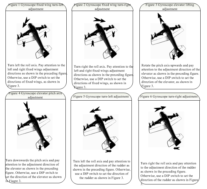
6. Check the signal output of gyro amendment. Please carefully check out if the output of each channel is perfectly correct based on the introduction of Gyro Gain Adjustment. If it is incorrect, please correct it according to Picture 2 & 6 of Flight Manual Parameters settings until it is perfectly correct.
7. Flying-wing (Delta-wing) should be mixed controlled by aileron and elevator; V-tail wing should be mixed controlled by elevator and rudder. Remote control should not be set into mixed mode, which should be completed by M6 flight control board.
8. Stunt flight locked mode. When the remote control return back to middle position, the flight manual will automatically lock the current flight mode in order to assure that three axial directions are in their positions ( it is natural that the angle of the axis may be in a little bit deviation caused by vibration, inaccuracy, and the properties of gyro, etc.) A compensation rudder volume will be output automatically after the deviation; thus, you will find kind of quiet deviations in aileron, elevator, and rudder. The deviation of axial angle, resulting from holding the plane in hand, is the auto-output compensation rudder of flight manual, which has to be returned back to the middle before takeoff. If there occurs deviation, please follow the 4 resolutions:
(a) Close down the channel of remote control switcher so that each channel steering gear will return automatically.
(b) Close down the channel of remote control before taking off, and then turn it on after the plane has taken off.
(c) Move the levers of aileron, elevator and rudder on the remote controller, and then each channel steering gear will automatically return back to the middle.
(d) Place the aircraft on the ground so that the flight manual will detect that the aircraft is static and then make it back to middle. 4 seconds later, the gyroscope will restart. If there is no remote control switcher, use (c) and (d) to settle the problem. Note that when you are using the flight manual for the first time, please try it for several times. Make sure that you have already comprehended the way of using flight manual and then fly the aircraft.
9. Sensitivity adjustment. The sensitivity is to adjust the control strength of the gyroscope on the airplane. The higher degree the gyroscope turns clock wisely, the greater the sensitivity. Usually, you are advised to adjust the sensitivity to 1/2 or 1/3 and then adjust it slightly as required. If you feel the airplane jitters greatly, adjust the sensitivity potentiometer counterclockwise slightly. Or adjust the sensitivity potentiometer clock wisely greatly to obtain optimal performance.
How to buy
Click here to buy JCX-M6 Flight Controller PV Fixed
