Difference between revisions of "Arduino JoyStick Module"
(→corresponding code) |
(→How to buy) |
||
| (8 intermediate revisions by the same user not shown) | |||
| Line 1: | Line 1: | ||
== Introduction == | == Introduction == | ||
| + | [[File:Joystick.jpg]] | ||
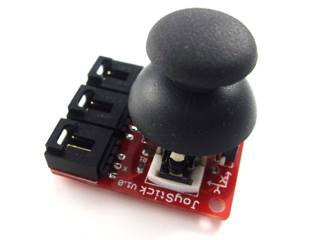
Just like a joystick on game console. you can control x, y and z dimensions input by this joystick module. It can be considered as combination of potentiometers and one button. Data type of the x, y dimensions are analog input signals and z dimension is digital input signal. thus the x and y ports connect to analog pins of Sensor Shield, while z port connects to digital pin. | Just like a joystick on game console. you can control x, y and z dimensions input by this joystick module. It can be considered as combination of potentiometers and one button. Data type of the x, y dimensions are analog input signals and z dimension is digital input signal. thus the x and y ports connect to analog pins of Sensor Shield, while z port connects to digital pin. | ||
== How this works == | == How this works == | ||
| − | + | [[File:Joy sch.jpg]] | |
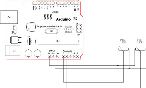
| + | The joystick in the picture is nothing but two potentiometers that allow us to messure the movement of the stick in 2-D. Potentiometers are variable resistors and, in a way, they act as sensors providing us with a variable voltage depending on the rotation of the device around its shaft. | ||
== How to use == | == How to use == | ||
| + | [[File:Joystick 1.jpg]] | ||
| + | |||
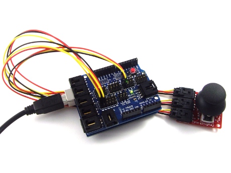
When using, it can connect with Arduino sensor shield,and connect Arduino corresponding pins through Arduino sensor cables. In the example below, the X axes and Y axes are respectively link to the analog input A1 and A0 ,and Z axis is connected to the digital I/O 7 pin: | When using, it can connect with Arduino sensor shield,and connect Arduino corresponding pins through Arduino sensor cables. In the example below, the X axes and Y axes are respectively link to the analog input A1 and A0 ,and Z axis is connected to the digital I/O 7 pin: | ||
| − | |||
== corresponding code == | == corresponding code == | ||
| Line 23: | Line 26: | ||
Serial.print("X:"); | Serial.print("X:"); | ||
Serial.print(value, DEC); | Serial.print(value, DEC); | ||
| − | |||
value = analogRead(1); | value = analogRead(1); | ||
Serial.print(" | Y:"); | Serial.print(" | Y:"); | ||
| Line 33: | Line 35: | ||
} | } | ||
| − | Referring Sample Code : | + | Referring Sample Code : |
| − | int JoyStick_X = 0; //x | + | int JoyStick_X = 0; //x |
| − | int JoyStick_Y = 1; //y | + | int JoyStick_Y = 1; //y |
| − | int JoyStick_Z = 3; //key | + | int JoyStick_Z = 3; //key |
| − | void setup() | + | void setup() |
{ | { | ||
pinMode(JoyStick_X, INPUT); | pinMode(JoyStick_X, INPUT); | ||
| Line 43: | Line 45: | ||
pinMode(JoyStick_Z, INPUT); | pinMode(JoyStick_Z, INPUT); | ||
Serial.begin(9600); // 9600 bps | Serial.begin(9600); // 9600 bps | ||
| − | } | + | } |
| − | void loop() | + | void loop() |
| − | { | + | { |
int x,y,z; | int x,y,z; | ||
x=analogRead(JoyStick_X); | x=analogRead(JoyStick_X); | ||
| Line 56: | Line 58: | ||
Serial.println(z ,DEC); | Serial.println(z ,DEC); | ||
delay(100); | delay(100); | ||
| − | } | + | } |
| + | |||
| + | |||
| + | == How to buy == | ||
| + | Click here to buy[http://www.geeetech.com/joystick-module-for-arduino-sensor-shield-p-434.html Arduino JoyStick Module ] | ||
Latest revision as of 06:04, 4 May 2012
Introduction
Just like a joystick on game console. you can control x, y and z dimensions input by this joystick module. It can be considered as combination of potentiometers and one button. Data type of the x, y dimensions are analog input signals and z dimension is digital input signal. thus the x and y ports connect to analog pins of Sensor Shield, while z port connects to digital pin.
How this works
The joystick in the picture is nothing but two potentiometers that allow us to messure the movement of the stick in 2-D. Potentiometers are variable resistors and, in a way, they act as sensors providing us with a variable voltage depending on the rotation of the device around its shaft.
How to use
When using, it can connect with Arduino sensor shield,and connect Arduino corresponding pins through Arduino sensor cables. In the example below, the X axes and Y axes are respectively link to the analog input A1 and A0 ,and Z axis is connected to the digital I/O 7 pin:
corresponding code
int sensorPin = 5;
int value = 0;
void setup() {
 pinMode(7, OUTPUT);
 Serial.begin(9600);
}
void loop() {
 value = analogRead(0);
 Serial.print("X:");
 Serial.print(value, DEC);
 value = analogRead(1);
 Serial.print(" | Y:");
 Serial.print(value, DEC);
 value = digitalRead(7);
 Serial.print(" | Z: ");
 Serial.println(value, DEC);
 delay(100);
}
Referring Sample Code :
int JoyStick_X = 0; //x
int JoyStick_Y = 1; //y
int JoyStick_Z = 3; //key
void setup()
{
 pinMode(JoyStick_X, INPUT);
 pinMode(JoyStick_Y, INPUT);
 pinMode(JoyStick_Z, INPUT);
 Serial.begin(9600); // 9600 bps
}
void loop()
{
     int x,y,z;
     x=analogRead(JoyStick_X);
     y=analogRead(JoyStick_Y);
     z=digitalRead(JoyStick_Z);
     Serial.print(x ,DEC);
     Serial.print(",");
     Serial.print(y ,DEC);
     Serial.print(",");
     Serial.println(z ,DEC);
     delay(100);
}
How to buy
Click here to buyArduino JoyStick Module


