Difference between revisions of "Geeetech Rostock mini G2 & G2s pro Quick Starter Manual"
(→How to modify and upload firmware.) |
(→Define the initial Z axis height) |
||
| (7 intermediate revisions by the same user not shown) | |||
| Line 24: | Line 24: | ||
5.Most of the code you need to modify is in Configuration.h . More details on this later. | 5.Most of the code you need to modify is in Configuration.h . More details on this later. | ||
| − | [[File: | + | [[File:Configuration.h.png|500px]] |
Find the value you need to compile according to your printer. ( we will elaborate which part of setting you need to change later one by one). Upon compiling, you can upload the firmware to your control board. Simply click [[File:561.png]]and [[File:789.png]] to upload. | Find the value you need to compile according to your printer. ( we will elaborate which part of setting you need to change later one by one). Upon compiling, you can upload the firmware to your control board. Simply click [[File:561.png]]and [[File:789.png]] to upload. | ||
| Line 88: | Line 88: | ||
[[File:3 Printer setting5.png|500px]] | [[File:3 Printer setting5.png|500px]] | ||
| + | |||
[[File:3 Printer setting6.png|500px]] | [[File:3 Printer setting6.png|500px]] | ||
| Line 133: | Line 134: | ||
Script 5: | Script 5: | ||
| + | |||
G0 X0 Y0 Z180 | G0 X0 Y0 Z180 | ||
| + | |||
M84 S0 | M84 S0 | ||
| Line 141: | Line 144: | ||
Write the script 1,2,3,4,5. Here we take the G2 & G2 pro as example. | Write the script 1,2,3,4,5. Here we take the G2 & G2 pro as example. | ||
| + | |||
Script 1: G0 X0 Y0 Z2 | Script 1: G0 X0 Y0 Z2 | ||
| Line 160: | Line 164: | ||
Script 5: | Script 5: | ||
| + | |||
G0 X0 Y0 Z180 | G0 X0 Y0 Z180 | ||
| + | |||
M84 S0 | M84 S0 | ||
| + | |||
Note: here we can add “M84 S0” to stop the motors from creeping down the rods when hanging in the air. | Note: here we can add “M84 S0” to stop the motors from creeping down the rods when hanging in the air. | ||
| Line 201: | Line 208: | ||
// Invert the stepper direction. Change (or reverse the motor connector) if an axis goes the wrong way. | // Invert the stepper direction. Change (or reverse the motor connector) if an axis goes the wrong way. | ||
| − | #define INVERT_X_DIR true // DELTA does not invert | + | #define INVERT_X_DIR true // DELTA does not invert |
| − | + | #define INVERT_Y_DIR true | |
| − | #define INVERT_Y_DIR true | + | #define INVERT_Z_DIR true |
| − | + | #define INVERT_E0_DIR false | |
| − | #define INVERT_Z_DIR true | + | #define INVERT_E1_DIR true |
| − | + | #define INVERT_E2_DIR false | |
| − | #define INVERT_E0_DIR false | + | #define INVERT_E3_DIR false |
| − | |||
| − | #define INVERT_E1_DIR true | ||
| − | |||
| − | #define INVERT_E2_DIR false | ||
| − | |||
| − | #define INVERT_E3_DIR false | ||
[[File:4 Homing the printer4.png|500px]] | [[File:4 Homing the printer4.png|500px]] | ||
| Line 226: | Line 227: | ||
1.First change the height of Z axis into 210 in the firmware. And upload it to the board | 1.First change the height of Z axis into 210 in the firmware. And upload it to the board | ||
| − | // Manual homing switch locations: | + | // Manual homing switch locations: |
| − | + | // For deltabots this means top and center of the Cartesian print volume. | |
| − | // For deltabots this means top and center of the Cartesian print volume. | + | #ifdef MANUAL_HOME_POSITIONS |
| − | + | #define MANUAL_X_HOME_POS 0 | |
| − | #ifdef MANUAL_HOME_POSITIONS | + | #define MANUAL_Y_HOME_POS 0 |
| − | #define MANUAL_X_HOME_POS 0 | + | #define MANUAL_Z_HOME_POS 210 // For delta: Distance between nozzle and print surface after homing. |
| − | + | #endif | |
| − | |||
| − | |||
| − | |||
| − | |||
| − | #endif | ||
[[File:5 Define the initial Z axis height 2.png|500px]] | [[File:5 Define the initial Z axis height 2.png|500px]] | ||
| Line 257: | Line 253: | ||
6. Open the firmware in IDE, locate the following code in IDE | 6. Open the firmware in IDE, locate the following code in IDE | ||
| − | //Manual homing switch locations: | + | //Manual homing switch locations: |
| − | + | #define MANUAL_HOME_POSITIONS // MANUAL_*_HOME_POS below will be used | |
| − | #define MANUAL_HOME_POSITIONS // MANUAL_*_HOME_POS below will be used | + | // For deltabots this means top and center of the Cartesian print volume. |
| − | + | #define MANUAL_X_HOME_POS 0 | |
| − | // For deltabots this means top and center of the Cartesian print volume. | + | #define MANUAL_Y_HOME_POS 0 |
| − | + | #define MANUAL_Z_HOME_POS 210// For delta: Distance between nozzle and print surface after homing. | |
| − | #define MANUAL_X_HOME_POS 0 | ||
| − | |||
| − | #define MANUAL_Y_HOME_POS 0 | ||
| − | |||
| − | #define MANUAL_Z_HOME_POS 210// For delta: Distance between nozzle and print surface after homing. | ||
Then you can change the 210 into the height you got (e.g.205 or 206 ) in the firmware and upload it. ( Disconnect the printer first) | Then you can change the 210 into the height you got (e.g.205 or 206 ) in the firmware and upload it. ( Disconnect the printer first) | ||
| Line 567: | Line 558: | ||
3.Click printing setting> extruder, change the number of extruder to 1. | 3.Click printing setting> extruder, change the number of extruder to 1. | ||
| − | + | 4.Open slis3r> configuration | |
| − | + | ||
| + | 5.Click file>Load the config.file you download before. | ||
[[File:12312.png|500px]] | [[File:12312.png|500px]] | ||
| Line 574: | Line 566: | ||
[[File:8 Slic3r configuration3.png|500px]] | [[File:8 Slic3r configuration3.png|500px]] | ||
| − | + | 6. Save the three parameters as G2 (or anything you like). | |
[[File:10 Printing test4.png|500px]] | [[File:10 Printing test4.png|500px]] | ||
| Line 580: | Line 572: | ||
[[File:10 Printing test5.png|500px]] | [[File:10 Printing test5.png|500px]] | ||
| − | 1.Note the nozzle size below, set it according to your printer, the default kit is 0.4mm. | + | 1.Note the nozzle size below, set it according to your printer, the default kit is 0.4mm. |
| − | 2. The Extruder offset is x:0, y:0 mm | + | |
| + | 2. The Extruder offset is x:0, y:0 mm | ||
[[File:10 Printing test6.png|500px]] | [[File:10 Printing test6.png|500px]] | ||
| − | + | 7. Confirm the start and end G-code. They should be like this. | |
[[File:8 Slic3r configuration8.png|500px]] | [[File:8 Slic3r configuration8.png|500px]] | ||
| Line 591: | Line 584: | ||
We have covered all the important settings. For other parameters you need to learn by yourself with the increasing of your 3D printing experience. | We have covered all the important settings. For other parameters you need to learn by yourself with the increasing of your 3D printing experience. | ||
| − | + | 8.Choose the printer and printing settings, filament settings we just saved in the drop-down menu. | |
Here we choose G2. | Here we choose G2. | ||
| Line 598: | Line 591: | ||
| − | + | 9.Load the stl. File you will print from Object placement > icon. Direct to the file and open it. | |
[[File:10 Printing test9.png|500px]] | [[File:10 Printing test9.png|500px]] | ||
| − | + | 10. Stl. File is successfully loaded. | |
[[File:10 Printing test10.png|500px]] | [[File:10 Printing test10.png|500px]] | ||
| − | + | 11.You can see it in the preview window. And you can choose different point of view by clicking the cubic on the left. | |
[[File:10 Printing test11.png|500px]] | [[File:10 Printing test11.png|500px]] | ||
| − | + | 12. Click Slic3r> slice with Slic3r. | |
[[File:10 Printing test12.png|500px]] | [[File:10 Printing test12.png|500px]] | ||
| Line 617: | Line 610: | ||
[[File:10 Printing test13.png|500px]] | [[File:10 Printing test13.png|500px]] | ||
| − | + | 13 After slicing, you will get the following information about this printing job. | |
[[File:10 Printing test14.png|500px]] | [[File:10 Printing test14.png|500px]] | ||
| − | + | 14 click G-code Editor to save the file for future use. Or if you have SD card, you can click SD card to save it in the SD card. | |
[[File:10 Printing test15.png|500px]] | [[File:10 Printing test15.png|500px]] | ||
| − | + | 15. Click manual control and remove the slash on fan, heated bed and extruder 1.(If you are using extruder 1 now) | |
[[File:10 Printing test16.png|500px]] | [[File:10 Printing test16.png|500px]] | ||
| − | + | 16.Click start print job to begin. | |
[[File:10 Printing test17.png|500px]] | [[File:10 Printing test17.png|500px]] | ||
| − | + | 17.When the temperature reaches the preset value, the printer will start printing, you will see the operation track of the print head as shown below. | |
[[File:10 Printing test18.png|500px]] | [[File:10 Printing test18.png|500px]] | ||
| Line 656: | Line 649: | ||
[[File:10 Printing test21.png|500px]] | [[File:10 Printing test21.png|500px]] | ||
| − | + | 18.Load the stl. File you will print from Object placement > icon. Direct to the file and open it. Load both files. | |
[[File:10 Printing test9.png|500px]] | [[File:10 Printing test9.png|500px]] | ||
| − | + | 19. Stl. File is successfully loaded. | |
[[File:10 Printing test23.png|500px]] | [[File:10 Printing test23.png|500px]] | ||
| Line 676: | Line 669: | ||
[[File:10 Printing test26.png|500px]] | [[File:10 Printing test26.png|500px]] | ||
| − | + | 20.Assign extruder for each file. | |
[[File:10 Printing test27.png|500px]] | [[File:10 Printing test27.png|500px]] | ||
| − | + | 21. Click Slic3r> slice with Slic3r. | |
[[File:10 Printing test12.png|500px]] | [[File:10 Printing test12.png|500px]] | ||
| Line 690: | Line 683: | ||
[[File:10 Printing test13.png|500px]] | [[File:10 Printing test13.png|500px]] | ||
| − | + | 22 After slicing, you will get the following information about this printing job. | |
[[File:10 Printing test31.png|500px]] | [[File:10 Printing test31.png|500px]] | ||
| − | + | 23 click G-code Editor to save the file for future use. Or if you have SD card, you can click SD card to save it in the SD card. | |
[[File:10 Printing test15.png|500px]] | [[File:10 Printing test15.png|500px]] | ||
| − | + | 24. Click manual control and remove the slash on fan, heated bed and extruder 1.(If you are using extruder 1 now) | |
[[File:10 Printing test33.png|500px]] | [[File:10 Printing test33.png|500px]] | ||
| − | + | 25.Click start print job to begin. | |
[[File:10 Printing test17.png|500px]] | [[File:10 Printing test17.png|500px]] | ||
| − | + | 26.The printer will home first and wait till the temperature reaches the preset value, the printer will start printing, you will see the operation track of the print head as shown below. | |
[[File:10 Printing test35.png|500px]] | [[File:10 Printing test35.png|500px]] | ||
Latest revision as of 06:19, 20 October 2015
Please DO NOT rush to start your first printing after assembly, as this is a DIY kit, some parameters of the printer may be different from each other, you need to modify the firmware according the the real situation of your printer. You are advised to read through the whole set-up instructions step by step to get a whole picture of what you will be doing and stick to our instructions before you start with your printer. Do not skip any details.
Contents
How to modify and upload firmware.
In the following set-up process, you will need to modify and upload the firmware by yourself, so, first of all, let’s start with the firmware compiling and uploading process.
1. Download the firmware here:firmware
Firmware for Delta Rostock mini G2 &G2s pro
2. Connect GT2560 to your PC with a USB cable,install FTDI drive. Usually it will install automatically. If not you need to install manually. download the FTDI driver here.
3. If there is nothing wrong with the hardware of board, you can find COM port in device manager. But every computer has different COM watchword, you need check by yourself.
4. Unzip the firmware, drag all the files into Arduino IDE.(I use Arduino1.0.5),choose Board\Arduino Mega or Mega2560,and selects ATmega2560(Mega2560) as default Processor. The order cannot be wrong. Selects the COM port you find in the device manager.


5.Most of the code you need to modify is in Configuration.h . More details on this later.

Find the value you need to compile according to your printer. ( we will elaborate which part of setting you need to change later one by one). Upon compiling, you can upload the firmware to your control board. Simply click ![]() and
and ![]() to upload.
to upload.
( Note: You need to disconnect the printer to Repetier Host before uploading).

Compiling
Uploading

Upload successfully
Printer preparing
Bed leveling
Put a level meter on the bed when adjusting the 3 screws of the bed to check if it is level.

Or you can use the such a cube use a reference height about 10mm to make sure that each top of each bed mounting point is the same after tightening the wing nuts. Simply place a 10mm cube next to the bed (not under!), and tighten the screw till the cube rightly fill gap between the bed and the base plate. Take out the cube and repeat for the other two mounts.
.png)
- To protect the bed and the nozzle from crashing, please attach a piece of tape on the bed.

Printer setting
Step1. Connect the USB to your Rostock mini G2 or G2s and power it up. You can see the LED lights and fan come to life, you may be able to hear the motors idling.
Step 2. Open Repetier Host and ensure that you have a valid port selected for communications. To do this, simply click “Printer Settings” in the upper right-hand corner to bring up the printer settings menu.

If you don’t know what the parameters mean, just hover your mouse over the item, the explanatory note will prompt up. As shown below:

Step 3. Choose the Connection menu to select the COM6 port and the Baud rate 250000. Click OK to continue.

If you can not find the COM port, you can check the device manager to see which port it is).
If you still cannot find the port, please re -install your USB driver here
Step4 set the printing speed. And un-check the disable the motors after job/kill.

Step5. Set the number and the offset of the extruders (offset only need for duan extruder printer),choose the nozzle size and different colors for each.


Step6 Choose printer shape. This is very important. Choose printer type as Rostock Printer (circular shape) and set the following parameters
Home X: 0
Home Y: 0
Home Z: Max
Printer Radius: 100mm
Printable height: 200mm ( this is the corresponding height in the firmware, remember to modify this each time after you change the height in the firmware)

Step7. Write the script 1,2,3,4,5
We will use this script as shortcuts later to move the print head to the corresponding point. For each point, keep the Z as 2.
For G2 or G2pro: (0, 0, 2) (0,50, 2) (43.3, -25, 2) (-43.3,-25, 2)
For G2s or G2s pro: (0, 0, 2) (0,63, 2)(43.3,-2, 2) (-43.3,-2, 2)
So we can set the following script.
| Code | G2 or G2pro | G2s or G2s pro |
|---|---|---|
Apart from the above 4 script, we need to add the fifth code to keep the print head staying in the air and will not creep down the rods.
Script 5:
G0 X0 Y0 Z180
M84 S0
When you click the script icon, the print head will move to the corresponding test point as shown in the following picture.

Write the script 1,2,3,4,5. Here we take the G2 & G2 pro as example.
Script 1: G0 X0 Y0 Z2

Script 2: G0 X0 Y50 Z2

Script 3: G0 X43.3 Y-25 Z2

Script 4: G0 X-43.3 Y-25 Z2

Script 5:
G0 X0 Y0 Z180
M84 S0
Note: here we can add “M84 S0” to stop the motors from creeping down the rods when hanging in the air.

Step8. Remember to name the printer as delta or as you like, next time you open the Repetier Host, just choose the name of the printer, you don’t have to set the above parameters again.

Step9. Hit "connect" in the upper left-hand corner. You should see the details of the connection in the console window in the bottom section of the screen. If it is


Homing the printer
Homing is the first and foremost hing you need to test. To home the printer, you can check if the three axis of the printer move in the same direction,if not, there will be crack for the spider and the carriage. Before homing, you need to follow the next steps.
1.Go to printer setting> printer. Set the travel feed rate and the Z axis feed rate as 300 mm/min. (Even though we have set the speed as slow as possible for you, you still need to adjust the feed rate. )

2.Hook up the probe with your hand, we are not testing the auto-leveling function right now. So, just leave it alone.

3. Move the extruder head to the middle and be ready for emergency stop. You can click the emergency stop icon on the Repetier host or shut the power supply directly.

Click Homing icon, you will see the three carriages move upwards till the bolt on the carriage hit the endstop.
If the three axis move in the different directions,such as one moves downwards, please check the direction setting in the firmware. E.g. If Y moves in the revers way, find the following code in configuration.h of the firmware, and change “true” to “false”. Re-upload the firmware and home again.(Remember to disconnect the printer to the Repetier Host.)
// Invert the stepper direction. Change (or reverse the motor connector) if an axis goes the wrong way.
 #define INVERT_X_DIR true // DELTA does not invert
 #define INVERT_Y_DIR true
 #define INVERT_Z_DIR true
 #define INVERT_E0_DIR false
 #define INVERT_E1_DIR true
 #define INVERT_E2_DIR false
 #define INVERT_E3_DIR false

Define the initial Z axis height
If the printer can home normally, the three axis move in the same directions(Up), we can set the initial height of the Z axis now, but this value may not be the final height. ( For the G2s and G2s pro, the height is on the base of the hotend 1.)

1.First change the height of Z axis into 210 in the firmware. And upload it to the board
 // Manual homing switch locations:
 // For deltabots this means top and center of the Cartesian print volume.
 #ifdef MANUAL_HOME_POSITIONS
 #define MANUAL_X_HOME_POS 0
 #define MANUAL_Y_HOME_POS 0
 #define MANUAL_Z_HOME_POS 210 // For delta: Distance between nozzle and print surface after homing.
 #endif

2 Upon uploading, change the corresponding setting in the Repetier Host and connect.

3.Use manual control to move the Z axis down to the building platform till the nozzle just touches the bed. When moving the Z axis, please slow it down. Move 0.1mm per click.


5. Read the coordinates of the Z axis when the nozzle just touches the bed. E.g. if it is (0,0,4), then the Z axis height is 210-4=206。If it is (0,0,5) the height is 210-5=205.
(*210 is height we just set in the firmware. 4 is the Z coordinate we read)
6. Open the firmware in IDE, locate the following code in IDE
 //Manual homing switch locations:
 #define MANUAL_HOME_POSITIONS  // MANUAL_*_HOME_POS below will be used
 // For deltabots this means top and center of the Cartesian print volume.
 #define MANUAL_X_HOME_POS 0
 #define MANUAL_Y_HOME_POS 0
 #define MANUAL_Z_HOME_POS 210// For delta: Distance between nozzle and print surface after homing.
Then you can change the 210 into the height you got (e.g.205 or 206 ) in the firmware and upload it. ( Disconnect the printer first) Upon uploading the firmware, you need to change the printing setting in the Repetier host.
7. Choose printer shape. This is very important. Choose printer type as Rostock Printer(circular shape)
Home X: 0
Home Y: 0
Home Z: Max
Printer Radius: 100mm
Printable height: 205mm (* the corresponding height you put in the firmware)

Reconfirm the Z axis height
Here, we are not measuring the height, but to adjust the printer to make the height at 205mm. That means the following adjusting is based on the the Z axis height of 205mm.
Step1. Homing the printer.
Step2. Tighten the screw trigger for each endstop, make sure they reach out as long as possible.
.png)
Adjust the screw on these 3 carriages.
Step3.Using G-code command to send the print head to the test points and observe the distance between the nozzle and the print surface separately for the test point 2,3,4.
Click 2 on the manual control manual. The print head will move to the corresponding point.

When it stopped, use manual control to move the Z axis down to the building platform till the nozzle just touches the bed. When moving the Z axis, please slow it down. Move 0.1mm per click.
When the nozzle just touches the bed, read the Z coordinate.
If the nozzle touches the bed at the height of 2mm, but not 0 mm, you need to unscrew the bolts on the Z axis carriage. (Test point 2 is near the Z axis).
If the print head has reached to 0mm, but not touched the bed, you need to screw the bolts tightly.
Repeat the steps for point 3 and 4.
You may need to adjust again and again till the Z coordinates are 0 for the three point when they touch the bed.
At this step, we are trying to adjust the distance between the nozzle and the print surface to keep the center point and its around point in one plain, that is to say,
we need to make sure that when the nozzle touches the bed, whichever point it is, the Z
Coordinate value should be the same, or almost the same.
You are required to operate again and again till you get a satisfied result.
Step 4. If the 3 points touch the bed at 0mm height. We can make sure that the peripheral points are in one plane. Now we need to check the center point.
Click script 1 to send the print head to center point. Then use manual control to move the Z axis down to the building platform .

- If the nozzle touches the center point at the height of 2mm, but not 0 mm, that means the bed is a convex surface, you should reduce the DELTA_RADIUS from 1 to 0 for example.
- If the print head has reached to 0mm, but hasn’t touched the bed, that means the bed is a concave surface, you should increase the DELTA_RADIUS from 1 to 2 for example.
Find the following code in the firmware and upload again after modifying.
(For each 1.0 unit increase or reduce of the DELTA_RADIUS, the z printing volume will increase or reduce 0.2 unit)
#define DELTA_RADIUS
(DELTA_SMOOTH_ROD_OFFSET-DELTA_EFFECTOR_OFFSET-DELTA_CARRIAGE_OFFSET+1)

You may have to adjust this for many times to keep the center point and its around point in one plane. (Be patient please)
After the above adjusting, we can almost confirm the printing volume, the height of the Z axis in other words. That is 205mm as we set in the firmware.
If you want to make it more accurate, you can test again refer to the steps in 9.5 Define the initial Z axis height.
When the height of the Z axis is determined, we have win half the battle.
Hotend leveling
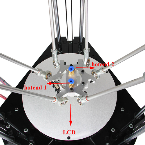
This step is exclusive for the dual extruder model. As the above adjusting is only based on the hotend 1, now, we need to level the two hotend. You can adjust the M6 nut as the arrows show. Loose the nut, you can screw the barral to make the second nozzle flush with the first one. ( DO NOT adjust the nut near the heating block or it will cause oozing if you loos it.).


Slic3r configuration
After the above setting, we can go on with the slicer setting. 1. Set the bed shape. In the latest version of Slic3r,V1.2.7, you can set the bed shape, this is very important when printing with your delta Rostock mini. go to general manual, click set button, choose circular and fill in the diameter of the printer bed.


if your slic3r is not the latest version, you can update or download it here, unzip the file and drag them into the directory of your previous slic3r directory. do please delete the old version. Restart your Repetier and continue.

Click OK to continue.

Step 3. Save the three parameters as G2s or G2 (according to your printer and the config file you choose, here i choose G2s.)


2.Confirm the parameters.
1)confirm the start and end G-code. They should be like this.

2)confirm the extruder offset. One is 13, another is -13.


For G2 and G2 pro, just set the number of the extruder as 1.

We have covered all the important settings. For other parameters you need to learn by yourself with the increasing of your 3D printing experience.
Start Auto-leveling function
Though we have added an auto-leveling probe for the Rostock mini, but generally there is no G-code in the sli3er, so we need to add the G29 command to the sli3er.
9.1 Start G29 command in Slic3r. Step1. Click Slicer and configure, waiting for a minute till the slicer window prompt up.

Step2. Choose printer setting> Custom G-code. You can see from the start G-code, there is no G29.

So you need to add the G29 after G28 to start it. And change Z5 into Z50.

Save the current printing setting, click “OK” to continue.

9.2 Check the status of endstop
Before going to set up for the auto-leveling, we need to check the status of the endstops.
1.Check the wire connection. the correct connection is as follow:

2.Put down the auto-level probe. And make sure the probe is not blocked by the red wires.

3.Homing the printer

4.Send M119 command Send the command M119 to verify the endstop first.

You can see the following message at the bottom of the Repetier Host.
- x_max,y_max,z_max is for the endstop of the three axis:
if the endstop is triggered, the feedback is Triggered; If the endstop is not triggered, the feedback is Open.
- z_min is for the probe:
When probe is put down, the feedback is Open; When probe is hooked up, the feedback is Triggered; If the status is normal, we can go on with the auto-leveling set-up.
9.3 Define the Z_PROBE_OFFSET
You can calculate the Z_PROBE_OFFSET values with this procedure:
Step1. Put down the prob.
Step2. Homing the printer.
Step3. Use manual control to move the print head to the building platform till the prob just touches the bed. When moving the Z axis, please slow it down to 0.1mm or
0.01mm per click.
Step4. When you hear the click of the endstop, you can get the coordinate of the prob on the manual control panel. In my case, it is 【19, 11, 1.2】, you can add it to
the following settings. (Note the minus sign)
// Offsets to the probe relative to the extruder tip (Hotend - Probe)
// X and Y offsets must be integers
- define X_PROBE_OFFSET_FROM_EXTRUDER -19 // Probe on: -left +right
#define Y_PROBE_OFFSET_FROM_EXTRUDER -11  // Probe on: -front +behind

#define Z_PROBE_OFFSET_FROM_EXTRUDER -1.2  // -below (always!)
Then modify the Z_PROBE_OFFSET in the firmware and upload again.

9.4 Verify the auto-leveling result. Auto-leveling probe is controlled by G29 command. As this is a DIY 3d printer, you may need to help it complete the leveling: 1.You need to put down the auto-leveling probe manually.
 2.Homing the printer.
3.Send G29 command.

4.Auto-leveling probe will probe the the pre-setted probing points. After probing, the print head will raise up a bit and stop in the air.
 5.Hook up the probe manually.

3.Send G1X0Y0 command to move the printing head to the center (0,0).
 4.Click -Z icon on manual control to move the print head down until it rightly touches the print bed.

5. Send M114 command to get the present coordinates.

6. If the coordinate is (0,0,0), the auto-leveling is successful.

7.If not, you need to modify the #define Z_PROBE_OFFSET_FROM_EXTRUDER -1.2 , e.g. Reduce -1.2 to -1.4, and then re-upload the firmware and test again.
8.You may have to test it for more than once, but for the sake of better printing object,please be patient. 9.Once auto-leveling is set up, hook up the probe manually. Then you can print your first prints. Please be patient for the calibration process, if you need helps, please post your problem on our forum, our tech support will help you.
9.5 Overall steps for the auto-leveling calibration
1.Manually put down the probe, then send M119 command to check if the Z-min is open.
2.Send G28 command to auto home the printer.
3.Send G29 command to start the auto-leveling. *there might be collisions, please always be ready to cut off the power supply.
4.After sending G29, the printing head will move down, and hit the pre-set probing point, after the probing, the printing head will go up.
5.After the leveling, the printing head will raise up and stop, meaning the leveling is finished. You should have the probe back (as the spring on the probe is a bit tight, to make it easier, you can use your finger to push up the probe)
6.Send G1X0 Y0 command to move the printing head to(0,0).
7.Click -Z icon on manual control to move the print head down until it touches the print bed just enough. Send M114 command to get the present coordinates. If the coordinate is (0,0,0), the auto-leveling is successful. If not, you need to modify the Z_PROBE_OFFSET_FROM_EXTRUDER , e.g. Reduce -1.2 to -1.5, and then re-upload the firmware and test again.
8.You may have to test it for more than once, but for the sake of better printing object,please be patient.
9.Once auto-leveling is set up, Hook up the probe manually. Then you can print your first prints.
Please be patient for the calibration process, if you need helps, please post your problem on our forum, our tech support will help you.
Printing test
So far,the printer is perfectly calibrated, you can start to print with the printer. You are advised to start with some simple models to test the printer with one extruder, with the increase of your experience, you can try to print with dual extruder. Example1. Print with one extruder. 1. Load the filament into the pipe from the push-fitting on the extruder.

2.Download this stl.file to test printing. And unzip it.

3.Click printing setting> extruder, change the number of extruder to 1.
4.Open slis3r> configuration
5.Click file>Load the config.file you download before.
![]()
6. Save the three parameters as G2 (or anything you like).


  1.Note the nozzle size below, set it according to your printer, the default kit is 0.4mm.

  2. The Extruder offset is x:0, y:0 mm

7. Confirm the start and end G-code. They should be like this.
We have covered all the important settings. For other parameters you need to learn by yourself with the increasing of your 3D printing experience.
8.Choose the printer and printing settings, filament settings we just saved in the drop-down menu.
Here we choose G2.

9.Load the stl. File you will print from Object placement > icon. Direct to the file and open it.

10. Stl. File is successfully loaded.

11.You can see it in the preview window. And you can choose different point of view by clicking the cubic on the left.

12. Click Slic3r> slice with Slic3r.


13 After slicing, you will get the following information about this printing job.

14 click G-code Editor to save the file for future use. Or if you have SD card, you can click SD card to save it in the SD card.

15. Click manual control and remove the slash on fan, heated bed and extruder 1.(If you are using extruder 1 now)

16.Click start print job to begin.

17.When the temperature reaches the preset value, the printer will start printing, you will see the operation track of the print head as shown below.

If you want to stop the printing job, just click pause.

Now you can take a rest and wait till the model is built.
Example 2. Print with dual extruder.
1.Download the stl. File here and unzi
2. Click printing setting> extruder, change the number of extruder to 2.

3. Choose the printer and printing settings, filament settings we just saved in the drop-down menu. Here we choose G2s.

18.Load the stl. File you will print from Object placement > icon. Direct to the file and open it. Load both files.
19. Stl. File is successfully loaded.

Now, you can see the two files are separated. You need to put them together.

You need to put them together. Choose the file and click center icon on the top separately.

Now the two files are centered and combined together.

20.Assign extruder for each file.

21. Click Slic3r> slice with Slic3r.
Choose No to continue.

22 After slicing, you will get the following information about this printing job.

23 click G-code Editor to save the file for future use. Or if you have SD card, you can click SD card to save it in the SD card.
24. Click manual control and remove the slash on fan, heated bed and extruder 1.(If you are using extruder 1 now)

25.Click start print job to begin.
26.The printer will home first and wait till the temperature reaches the preset value, the printer will start printing, you will see the operation track of the print head as shown below.

The printer is working now.
That is all for the geeetech rostock mini G2 and G2s pro. If you have any problem running the printer, please go to our forum for tech support.