Difference between revisions of "Delta Rostock mini G2"
(→Printer preparing) |
|||
| (28 intermediate revisions by the same user not shown) | |||
| Line 26: | Line 26: | ||
6. Further simplified structure and enhanced stability. | 6. Further simplified structure and enhanced stability. | ||
| + | |||
| + | |||
| + | =SOURCES= | ||
| + | |||
| + | download the STL file for the printed parts [http://www.geeetech.com/wiki/images/1/1e/Geeetech_delta_rostock_mini_G2_%26G2s_STL.rar here] | ||
=Specifications= | =Specifications= | ||
| − | Print Volume: | + | Print Volume: cylindrical,D:190mm,H:200mm |
Chassis: laser -cut acrylic plate | Chassis: laser -cut acrylic plate | ||
| Line 81: | Line 86: | ||
=Building instruction= | =Building instruction= | ||
| − | For detailed building instruction, please visit [http://www.geeetech.com/wiki/index.php/Delta_Rostock_mini_G2_Building_Instruction here]. | + | For detailed building instruction, please visit [http://www.geeetech.com/wiki/index.php/Delta_Rostock_mini_G2_Building_Instruction here], or you can download the [http://www.geeetech.com/wiki/images/8/85/Delta_Rostock_mini_G2%26_G2s_building_instruction.pdf PDF version ]. |
=Install drivers and software= | =Install drivers and software= | ||
| Line 227: | Line 232: | ||
=How to set up= | =How to set up= | ||
| + | |||
| + | <font color=red> Please '''DO NOT''' rush to start your first printing and start the Auto-leveling command right now, as this is a DIY kit, some parameters of the printer may be different from each other, you need to modify the firmware according the the real situation of your printer, | ||
| + | You are avised to read through the whole set-up instructions step by step to get a whole picture of what you will be doing and stick to our instructions. Do not skip any detailes.</font> | ||
| + | |||
| + | ==How to modify and upload firmware== | ||
| + | |||
| + | In the following set-up process, you will need to modify and upload the firmware by yourself, so, first of all, let’s start with the firmware comliling and uploading. | ||
| + | |||
| + | 1. Download the firmware here: | ||
| + | |||
| + | [http://www.geeetech.com/wiki/images/9/98/RKMA_GT2560_G2.zip Firmware for Delta Rostock mini G2] | ||
| + | |||
| + | [http://www.geeetech.com/wiki/images/6/64/RKMA_GT2560_G2S.zip Firmware for Delta Rostock mini G2S] | ||
| + | |||
| + | 2. Connect GT2560 to your PC with a USB cable,install FTDI drive. Usually it will install automaticlly. If not you need to install maually. | ||
| + | |||
| + | download lthe FTDI driver [http://www.ftdichip.com/Drivers/CDM/CDM%20v2.12.00%20WHQL%20Certified.exe here]. | ||
| + | |||
| + | 3. If there is nothing wrong with the hardware of board, you can find COM port in device manager. But every computer has different COM watchword, you need check by yourself. | ||
| + | |||
| + | 4. Unzip the firmware, drag all the files into Arduino IDE. I use Arduino1.0.5,choose Board\Arduino Mega or Mega2560,and selects ATmega2560(Mega2560) as default Processor. The order cannot be wrong. Selects the COM port you find in the device manager. | ||
| + | |||
| + | [[File:CHOOSE BOARD.png|500px]] | ||
| + | |||
| + | [[File:COM PORT.png|500px]] | ||
| + | |||
| + | 5 Most of the code you need to modify is in ''Configuration.h .'' | ||
| + | |||
| + | [[File:Configuration.h.png|500px]] | ||
| + | |||
| + | Find the value you need to comlile according to your printer. Upon compiling, you can upload the firmeare to your control board. Simply click veryfy and upload. | ||
| + | |||
| + | [[File:Uploading.png|500px]] | ||
| + | |||
| + | [[File:Upload succesfully.png|500px]] | ||
| + | |||
| + | |||
| + | |||
| + | ==Printer preparing== | ||
| + | |||
| + | |||
| + | 1. Adjust the printing bed | ||
| + | Put a level meter on the bed when adjusting the 3 screws of the bed to check if it is level. | ||
| + | |||
| + | [[File:PTFE tube1.jpg|500px]] | ||
| + | |||
| + | |||
| + | 2. To protect the bed and the nozzle from crashing, please attach a piece of tape on the bed. | ||
| + | |||
| + | [[File:Printer preparing.png|500px]] | ||
==Printer setting== | ==Printer setting== | ||
| + | |||
Step1. Connect the USB to your Rostock mini G2 or G2s and power it up. You can see the LED lights and fan come to life, you may be able to hear the motors idling. | Step1. Connect the USB to your Rostock mini G2 or G2s and power it up. You can see the LED lights and fan come to life, you may be able to hear the motors idling. | ||
| Line 245: | Line 301: | ||
Choose printer shape. This is very important. Choose printer type as ''Rostock Printer(circular shape)'' | Choose printer shape. This is very important. Choose printer type as ''Rostock Printer(circular shape)'' | ||
| − | Home X: | + | <font color=red>Home X: 0, |
Home Y: 0 | Home Y: 0 | ||
| Line 253: | Line 309: | ||
Printer Radius: 100mm | Printer Radius: 100mm | ||
| − | Printable height: | + | Printable height: 200mm</font> |
[[File:Printer Settings3.png]] | [[File:Printer Settings3.png]] | ||
| Line 262: | Line 318: | ||
[[File:Printer Settings4.png|500px]] | [[File:Printer Settings4.png|500px]] | ||
| − | + | ==Homing the printer== | |
| − | + | Homing is the first and foremostt hing you need to test. To home the printer, you can check if the three axis of the printer move in the same direction,if not, there will be crack for the spider and the carriage. | |
| − | + | Before homing, you need to follow the next steps. | |
| − | |||
| − | |||
| − | + | 1.Go to printer setting> printer. Set the travel feed rate and the Z axis feed rate as 300 mm/min. | |
| − | + | (Even though we have set the speed as slow as possible for you, you still need to adjust the feed rate. ) | |
| + | [[File:Feed rate.png|500px]] | ||
| − | + | 2.Hook up the probe with your hand, we are not testing the auto-leveling fuction right now. | |
| − | + | [[File:Auto-leveling3.jpg|500px]] | |
| − | + | 3. Move the extruder head to the middle and be ready for emergency stop. You can click the emergency stop icon on the repetier host or shut the power supply directly. | |
| − | |||
| − | + | 4. Go to the Manual Control and click the home icon. | |
| − | [[File:Printer | + | [[File:Printer Settings5.png]] |
| − | |||
| − | + | If the three axis move in the different directions, please check the conenction of the stepper motor wires. | |
| − | + | ==Define the initial Z axis height== | |
| − | + | If the printer can home normally, the three axis move in the same directions, we can set the height of the Z axis now, but this value may not be the final height. | |
| − | + | 1. You can use a rule or digital graphics to measure. The height of the Z axis means the distance between the nozzle and the building platform after homing. So you need to measure after homing. | |
| − | + | [[File:Z axis height.jpg|500px]] | |
| − | |||
| − | + | 2. Or you can use maual control to move the Z axis down to the building platform till the nozzle just touches the bed. When moving the Z axis, please slow it down. | |
| − | + | Move 0.1mm per click | |
| − | + | [[File:Move 0.1mm.png|500px]] | |
| − | |||
| − | |||
| − | + | 3.Read the coordinates of the Z axis when the nozzle just touches the bed. E.g. if it is (0,0,1), then the Z axis height is 200-1=199。If it is (0,0,2) the height is 200-2=198. | |
| − | |||
| − | + | <font corlor=red>(*200 is pre-set height in the firmware. 1 is the Z coordinate) </font> | |
| − | the | + | 4. Open the firmware in IDE, locate the following code in IDE |
| − | + | //Manual homing switch locations: | |
| − | + | #define MANUAL_HOME_POSITIONS // MANUAL_*_HOME_POS below will be used | |
| − | + | // For deltabots this means top and center of the Cartesian print volume. | |
| − | + | #define MANUAL_X_HOME_POS 0 | |
| − | + | #define MANUAL_Y_HOME_POS 0 | |
| − | + | #define MANUAL_Z_HOME_POS <font color=red>200</font>// For delta: Distance between nozzle and print surface after homing. | |
| − | + | Then you can change the 200 into the height you got (e.g.205 or 199 you get) in the firmware and upload it. | |
| − | |||
| − | + | Upon uploading the firmware, you need to change the printing setting in the Repetier host. | |
| − | + | Choose printer shape. This is very important. Choose printer type as Rostock Printer(circular shape) | |
| − | + | <font color=red>Home X: 0 | |
| − | |||
| + | Home Y: 0 | ||
| − | + | Home Z: Max | |
| + | Printer Radius: 100mm | ||
| − | * | + | Printable height: 205mm (* the height you put in the firmware)</font> |
| − | |||
| − | + | [[File:Printable height.png]] | |
| − | = | + | ==Define the final Z axis height== |
| − | |||
| − | + | Step1. Homeing the printer. | |
| − | + | Step2. Tighten the screw trigger for each endstop, make sure they reach as long as possibl. | |
| − | + | [[File:Diagonal rods6.jpg|500px]] | |
| − | + | Adjust the screw on these 3 carridges. | |
| − | + | Step3. Set 3 probing points (0,50)、(43.3,-25)、(-43.3,-25), using G-code command to adjust the print head to the 3 points and record the distance between the nozzle and the print surface separately. | |
| − | [[File: | + | [[File:Endstop adjust1.png]] |
| − | + | [[File:Endstop adjust2.png]] | |
| − | + | 1)send command: G0 X0 Y50 Z2, record the distance;e.g. it is 3mm in my case. | |
| − | |||
| − | |||
| − | |||
| − | |||
| − | |||
| − | |||
| − | |||
| − | + | 2)send command: G0 X43.3 Y-25 Z2, record the distance;e.g. it is 2.7mm in my case. | |
| − | + | 3)send G 0 X-43.3 Y-25 Z2, record the distance;e.g. it is 2.2mm in my case. | |
| − | + | [[File:Cordinates of the Z axis.png]] | |
| − | + | You may need to adjust again and again till the three distance are the same or at least very close. | |
| − | |||
| − | + | If the 3 numbers differ too much, you can manually move down the print head until the nozzle just hit the print bed, and screw the endstop screw trigger tightly. | |
| − | + | At this step, we are trying to adjust the distance between the nozzle and the print surface to keep the center point and its around point in one plain, that is to say, we need to make sure that when the nozzle touches the bed, whichever point it is, the Z | |
| + | Coordinate value should be the same, or almost the same. | ||
| − | + | You are required to operate again and again till you get a satisfied result. | |
| − | + | if the screw has no room to adjust, you need to change the following setting later, record it. you need to modify the DELTA_RADIUS | |
| − | + | (For each 1.0 unit increase or reduce of the DELTA_RADIUS, the z printing volume will increase or reduce 0.2 unit) | |
| − | |||
| − | |||
| − | |||
| − | |||
| − | + | #define DELTA_RADIUS (DELTA_SMOOTH_ROD_OFFSET-DELTA_EFFECTOR_OFFSET-DELTA_CARRIAGE_OFFSET<font color=red>+2.0</font>) | |
| − | |||
| − | |||
| − | |||
| − | |||
| − | |||
| − | |||
| − | + | <font color=red> | |
| − | + | *If the nozzle touches the center point but not the around points, that is a convex surface, you should reduce the DELTA_RADIUS from 2.0 to 1.0 for example. | |
| − | |||
| − | |||
| − | |||
| − | |||
| + | *If the nozzle touches the around points but not the center point, that is a concave surface, you should increase the DELTA_RADIUS from 2.0 to 3.0 for example.</font> | ||
| − | + | You may have to adjust this for many times to keep the center point and its around point in one plain. (the distance between the nozzle and the print bed). | |
| − | + | Modify it in the firmware and upload, test again, | |
| − | |||
| − | |||
| − | |||
| − | |||
| − | |||
| − | |||
| − | |||
| − | |||
| − | |||
| − | |||
| − | |||
| − | |||
| − | |||
| − | + | So far, we can get the exact height of the Z axis. | |
| − | |||
| − | |||
| − | + | ==check the status of endstop== | |
| − | |||
| − | |||
| − | |||
| − | |||
| − | |||
| − | |||
| − | |||
| − | |||
| − | |||
| − | |||
| − | |||
| − | |||
| − | |||
| − | |||
| − | |||
| − | = | ||
1. verify the endstop | 1. verify the endstop | ||
Before you risk any damage, you should test if you have configured the z-probe correctly. Send the command M119 to verify the endstop first. | Before you risk any damage, you should test if you have configured the z-probe correctly. Send the command M119 to verify the endstop first. | ||
| Line 478: | Line 474: | ||
You will see the X/Y/Z raise up till they hit the endstops. Then they will move down a bit and hit the endstops again before they stop (that is to increase the printing precision). | You will see the X/Y/Z raise up till they hit the endstops. Then they will move down a bit and hit the endstops again before they stop (that is to increase the printing precision). | ||
| − | '''Trouble shooting:''' | + | <font color=red>'''Trouble shooting:'''</font> |
The axis did not stop after hitting the endstops. | The axis did not stop after hitting the endstops. | ||
| Line 486: | Line 482: | ||
Note: unlike other machines, the origin here is not (0,0,0) but (0,0,MANUAL_Z_HOME_POS) | Note: unlike other machines, the origin here is not (0,0,0) but (0,0,MANUAL_Z_HOME_POS) | ||
| + | ==Define the Z_PROBE_OFFSET== | ||
| − | + | You can calculate the Z_PROBE_OFFSET values with this procedure: | |
| + | Put down the prob. Manual y move the print head down slowly, place the probe at the center of the print bed. When you hear the trigger of the endstop, you can get the coordinate on the Repetier host. In my case, it is <font color=red>【-20.35,11.75,0.3】</font>, you can add it to the following settings. | ||
| − | + | #define X_PROBE_OFFSET_FROM_EXTRUDER <font color=red>20.35</font> | |
| + | |||
| + | #define Y_PROBE_OFFSET_FROM_EXTRUDER <font color=red>-11.75</font> | ||
| + | |||
| + | #define Z_PROBE_OFFSET_FROM_EXTRUDER <font color=red>-0.3</font> | ||
| + | |||
| + | //these are the offsets to the probe relative to the extruder tip (Hotend - Probe), these values are very important, especially the Z_PROBE_OFFSET. | ||
| − | + | Then modify the Z_PROBE_OFFSET in the firmware and upload again. | |
| − | + | ||
| + | ==slic3r configuration== | ||
| + | ===printer setting=== | ||
| + | 1. set bed shape. | ||
| + | |||
| + | in the latest version of Slic3r,V1.2.7, you can set the bed shape, this is very important when printing with your delta rostock mini. go to general manual, click set button, choose circular and fill in the diameter of the printer bed. | ||
| + | |||
| + | [[File:Set bed shape.jpg|500px]] | ||
| + | |||
| + | |||
| + | * if your slic3r is not the latest version, you can update or download it [http://slic3r.org/download here], unzip the file and drag them into the directory of your previour slic3r directory. do please delete the old version. Restart your Repetier and continue. | ||
| + | |||
| + | 2.Start G29 Command | ||
| + | |||
| + | Thoughg we have added an auto-leveling probe for the Rostock mini, but generally there is no G-gode in the sli3er, so we need to add the G29 command to the sli3er. | ||
| + | |||
| + | Step1. Start G29 command in Slic3r. | ||
| + | |||
| + | Click Slicer and configure, waiting for a minute till the slicer window prompt up. | ||
| − | + | [[File:Printer Settings6.png]] | |
| + | |||
| + | Step2. Choose printer setting-- Custom G-code. | ||
| + | |||
| + | You can see from the start G-code, there is no G29. | ||
| + | |||
| + | [[File:Printer Settings7.png|500px]] | ||
| + | |||
| + | So you need to add the G29 after G28 to start it. And change Z5 into Z50. | ||
| + | |||
| + | [[File:Printer setting.jpg|500px]] | ||
| + | |||
| + | Save the current printing setting, click “OK” to continue. | ||
| + | |||
| + | [[File:Printer Settings9.png|500px]] | ||
| + | |||
| + | In case any cratch caused to your print bed, do not rush to test the auto-leveling command right now. | ||
=Calibration of auto-leveling = | =Calibration of auto-leveling = | ||
| Line 534: | Line 572: | ||
9.Once auto-leveling is set up, Hook up the probe manualy. Then you can print your first prints. | 9.Once auto-leveling is set up, Hook up the probe manualy. Then you can print your first prints. | ||
| + | |||
| + | |||
| + | =where to buy= | ||
| + | |||
| + | 1.[http://www.geeetech.com/delta-rostock-mini-g2-diy-kit-with-autoleveling-p-935.html?zenid=jlo49ls975q5jd6pc74fa88gu6 geeetech official online store]. | ||
Latest revision as of 06:24, 5 August 2015
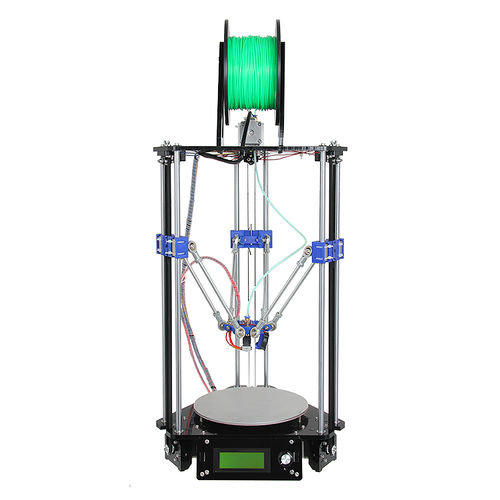
This Rostock mini G2 is a new upgraded delta 3D printer based on the modified design of the Geeetech Delta Rostock mini generation 1.
On the whole, the Rostock mini G2 succeeds the advantages of the previous version like small physical footprint, simple but really rigid frame, high positioning accuracy, flexible effectors, and very similar specification except that we add some innovative design.
This G2 is powered by our newly designed control system—GT2560 that supports 2 extruders and eliminates the complicated wiring of Mega2560+Ramps 1.4 and it is more space-saving and convenient.
We also add an auto-leveling auto-calibration device for G2;which means you do not have to adjust it every time before you start printing, after the first assembly work, you can almost plug and play.
In terms of printing filament, apart from PLA and ABS, G2 supports Nylon and wood filament, which enables more possibilities to create 3D printing project.
This G2 is also improved with a build-on LCD control panel; you can monitor the printing process in real time and with a SD card it can realize stand-alone printing, very convenient.
Contents
Main features
1. New updated control system.
2. Auto-leveling and auto-calibration.
3. More flexible effectors and diagonal rods.
4. More fluent printing process and higher precession.
5. Support PLA, ABS, Nylon and Wood filament.
6. Further simplified structure and enhanced stability.
SOURCES
download the STL file for the printed parts here
Specifications
Print Volume: cylindrical,D:190mm,H:200mm
Chassis: laser -cut acrylic plate
The Layer Thickness: 0.1mm
Layer Resolution: 0.1mm
Filament Diameter: 1.75, 3mm
Nozzle Diameter: 0.3, 0.35, 0.4, 0.5mm
Print Speed: 60 to 120 mm/sec
Print Plate Size: 210 x 3mm
Print Plate (Build Platform): aluminum plate + MK2A heatbed
XYZ Bearings: carbon steel
Stepper Motors: 1.8° step angle with 1/16 micro-stepping
Max Heated Bed Temp: about 110 ℃
Max Extruder Temp: about 240 ℃
AC Input: 115V/1.5A 230V/0.75A
Output:DC12V/0-15A
No. of Extruders: 1
Connectivity (Interface): USB, SD Card
Electronics: GT2560
3D printing Software: Repetier Host
CAD Input data file format supported: STL, G code
Client Operating System: Windows, Linux, Mac
Machine Dimensions: 320 x 320 x 870mm
Machine weight:8.5kg
Shipping box dimensions:495*395*195mm
Shipping box weight:9.5kg
Building instruction
For detailed building instruction, please visit here, or you can download the PDF version .
Install drivers and software
Install the drivers
Installing Drivers Before printing, you’ll need to install drivers. The kind of driver that a Rostock mini G2 and G2s requires in order to operate properly is called a USB Serial Driver. A USB Serial Driver is software that establishes a COM port.
Plug the USB into a USB port on your computer. Windows Update should automatically find and install the drivers. You’re done with installing the drivers!
Windows Manual Install Note: In some cases the drivers will not install on their own. The drivers for Windows can be found
here.
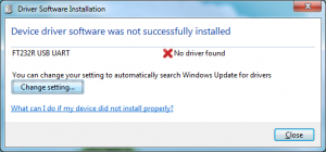
If the driver was not automatically installed, you may see this screen:
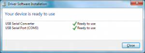
In this case, a. Click “Change Settings…” b. Select “Install driver software from Windows Update”. c. Click “Save Changes”. The FTDI drivers should now install successfully.
Attention: For those having difficulty selecting your COM port
If you have installed the USB serial driver successfully and you are still not able to connenct to your printer in Repetier Host, then windows has not recognized the newly installed driver. In Repetier Host, you may even notice an error message that is similar to this one:
Serial com error:System.IO.Ports.SerialErrorReceivedEventArgs
In some situations, a computer running windows will not automatically recognize a newly installed Serial driver. This means that you will have to update your newly installed driver manually.
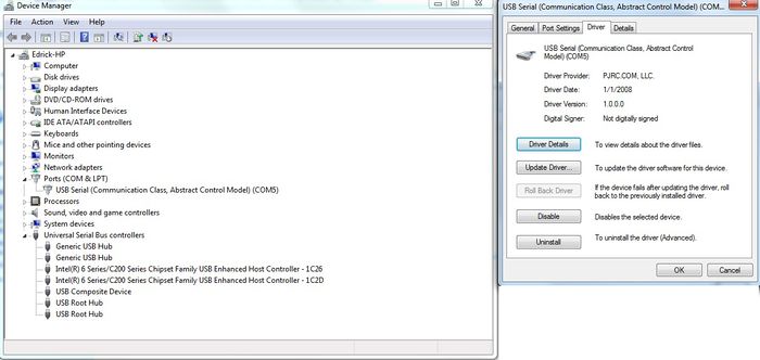
To manually update the driver, you will first need to plug the USB cable into your printer and attache the other end directly to one of your computer’s USB ports. Now, enter the ‘Device Manager’ in Windows and navigate to the hardware category called Ports (COM & LPT) and then left click on it once. You should notice the Ports category expand to reveal a Sub-Category called USB Serial (Communication Class, Abstract Control Model) (COM X); where X is the COM port number. You should be looking for that COM port number in Repetier Host after this procedure is completed; which can be found in “Printer Settings.”
You will need to right click on the USB Serial Sub-class and select proprties. In the drivers tab you will find a selection to update drivers, click on Update Drivers to access the next menu.
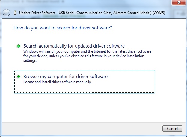
Now that you have selected which driver to update, you will have to tell Windows where the “updated” driver can be found. You should be presented with two options. Select “Browse my computer for driver software” to locate and install the driver software manually.
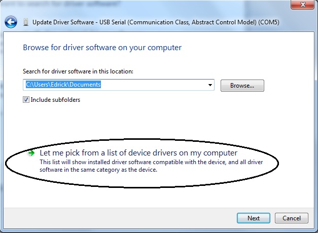
Next, you will be greeted by a menu that allows you to “Browse for driver software on your computer” You will be presented with two choices, select “Let me pick from a list of device drivers on my computer.” Now select the Serial port device and proceed with the installation.
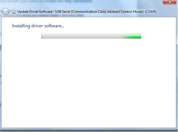
That is pretty much all there is to it. You will then see an installation indicator bar.
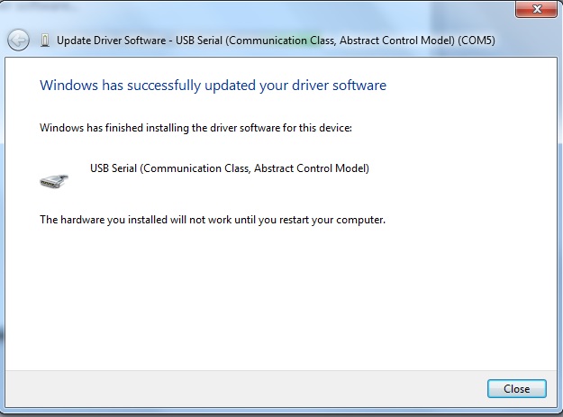
Once the installation is complete you will be notified that “Windows has successfully updated your driver software.” You will be prompted to restart your computer; you should do so.
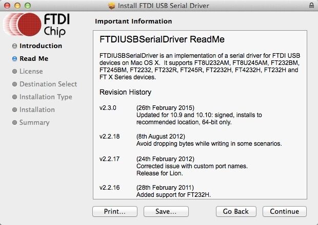
Macbook (OS X) Manual Install
Download link of driver: http://www.ftdichip.com/Drivers/VCP.htm
Download the driver that is compatible with system version.
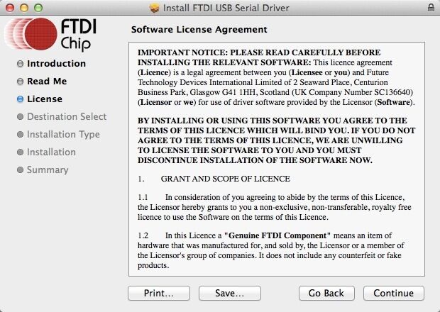
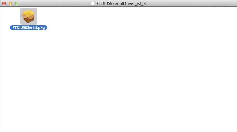
Open the downloaded file, you will see a .pkg file, Open "FTDIUSBSerial.pkg"
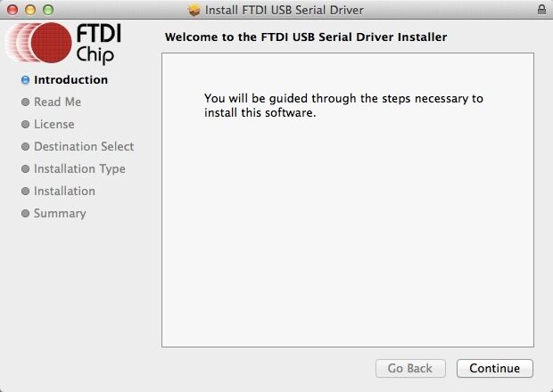
Click "Continue" in Instruction.
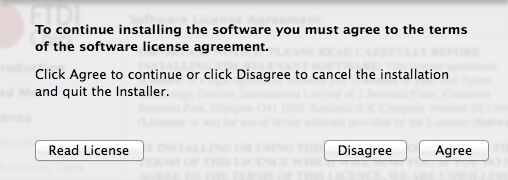
Click "Agree" to continue installation.
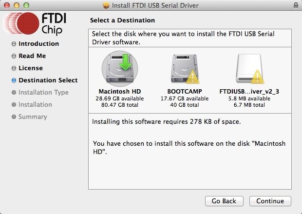
Select the installing destination and click "Continue".
Click "Install" in Installatin Type.
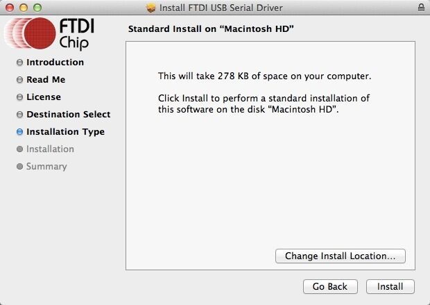
Mac will start to install the driver:
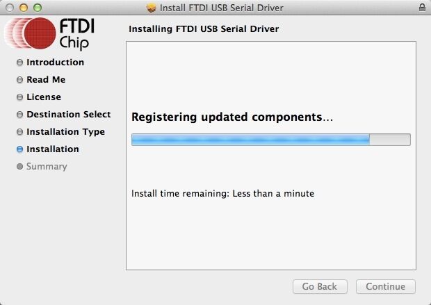
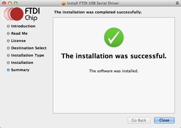
Once your computer restarts, try selecting the appropriate COM port and baud rate in Repetier Host and then connect.
Install Software
we will take windows OS as an example.
To install all required software by Rostock mini G2 and G2s, please follow the steps provided below.
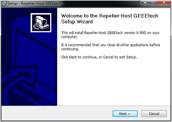
1) Download and install: RepetierGEEEtech
step 1,start the installer,choose the display language. step 2,click next to continue
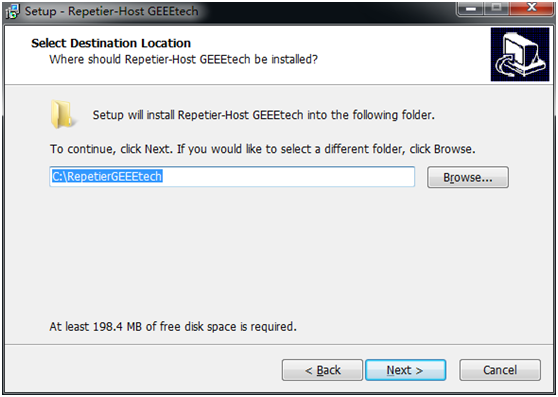
step3,select the destination where you would like to install the RepetierGEtechSetup.
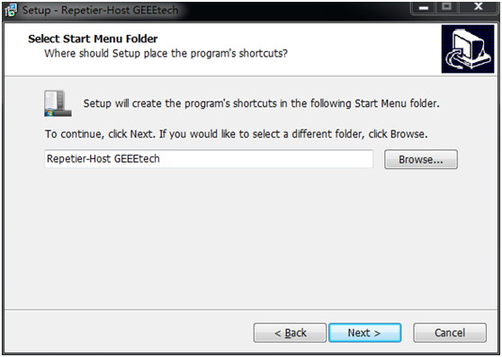
step4,select start menu folder and create a shortcut, click next to continue.
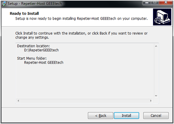
step 5,get ready to install. Click install.
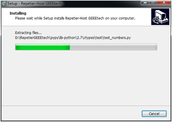
step 6,wait about half a minute while installing. The green bar will show you the rate.
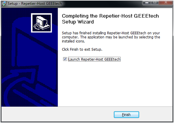
step 7,set up has finished the installing, you can choose to launch it immediately or exit out.
2) Plug the power cord into a wall outlet and the USB cable into a USB port on your computer. Windows should detect your motherboard and assign the appropriate driver.
3) Open Repetier Host and Connect to your Rostock mini G2 and G2s!
Click on the Manual Controls Tab and click in a direction X or Y to test your connection. If you are having difficulty connecting, please review the following supportive documentation: Installing Drivers and How to connect.
Please note that if you have difficulty connecting, there might have been an issue with the installation process. Ensure that the following have been installed:
Download and install the Serial Driver.
Download and install Microsoft .netFrameWork 3.5
In Mac, you can download Repetier for Mac" at:
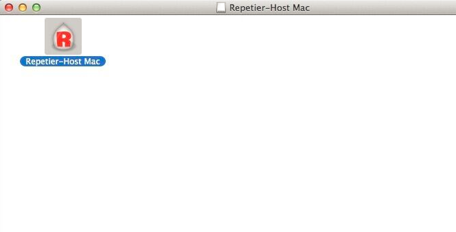
After downloading, open "Repetier-Host-Mac_56.dmg",then you will see the icon of "Repetier Host", open it.
How to set up
Please DO NOT rush to start your first printing and start the Auto-leveling command right now, as this is a DIY kit, some parameters of the printer may be different from each other, you need to modify the firmware according the the real situation of your printer, You are avised to read through the whole set-up instructions step by step to get a whole picture of what you will be doing and stick to our instructions. Do not skip any detailes.
How to modify and upload firmware
In the following set-up process, you will need to modify and upload the firmware by yourself, so, first of all, let’s start with the firmware comliling and uploading.
1. Download the firmware here:
Firmware for Delta Rostock mini G2
Firmware for Delta Rostock mini G2S
2. Connect GT2560 to your PC with a USB cable,install FTDI drive. Usually it will install automaticlly. If not you need to install maually.
download lthe FTDI driver here.
3. If there is nothing wrong with the hardware of board, you can find COM port in device manager. But every computer has different COM watchword, you need check by yourself.
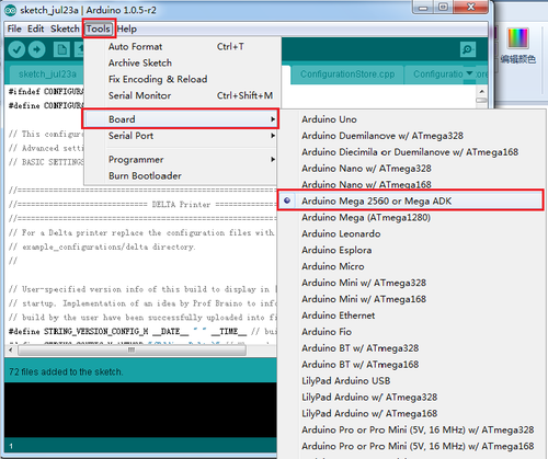
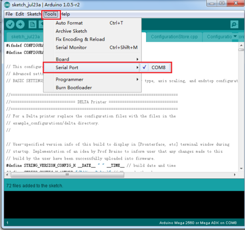
4. Unzip the firmware, drag all the files into Arduino IDE. I use Arduino1.0.5,choose Board\Arduino Mega or Mega2560,and selects ATmega2560(Mega2560) as default Processor. The order cannot be wrong. Selects the COM port you find in the device manager.
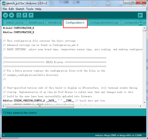
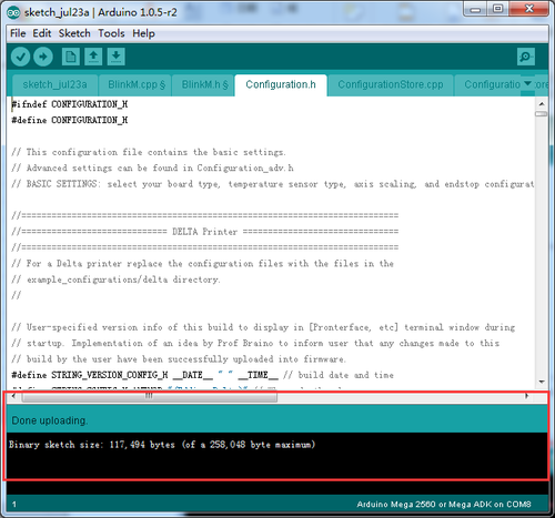
5 Most of the code you need to modify is in Configuration.h .
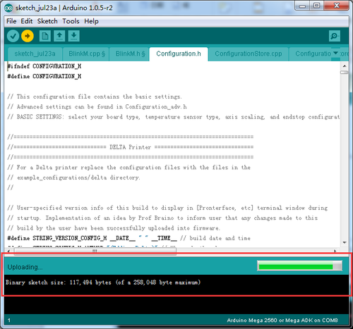
Find the value you need to comlile according to your printer. Upon compiling, you can upload the firmeare to your control board. Simply click veryfy and upload.
Printer preparing
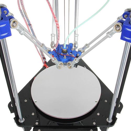
1. Adjust the printing bed Put a level meter on the bed when adjusting the 3 screws of the bed to check if it is level.
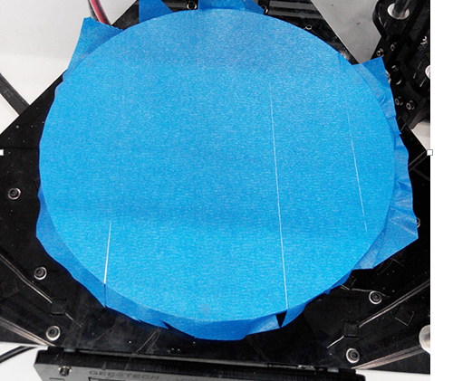
2. To protect the bed and the nozzle from crashing, please attach a piece of tape on the bed.
Printer setting
Step1. Connect the USB to your Rostock mini G2 or G2s and power it up. You can see the LED lights and fan come to life, you may be able to hear the motors idling.
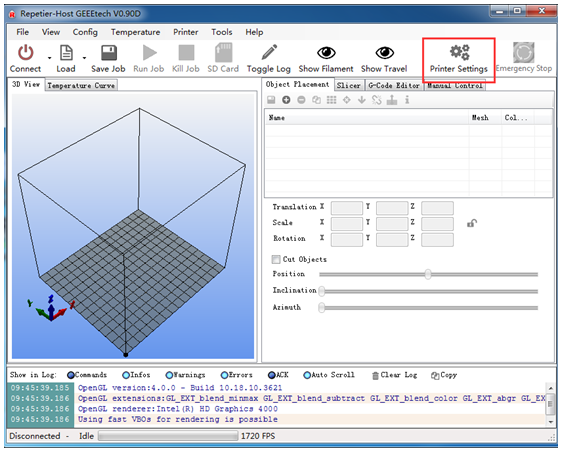
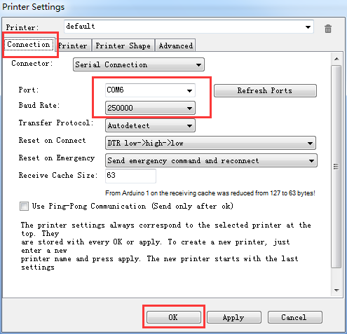
Step 2. Open Repetier Host and ensure that you have a valid port selected for communications. To do this simply, click “Printer Settings” in the upper right-hand corner to bring up the printer settings menu.
Step 3. Choose the Connection menu to select the COM6 port and the Baud rate 250000. Click OK to continue.
If you can not fond the COM port, click “refresh ports” and see if it appears. (It is usually the last one; you can check the device manager to see which port it is). PS: if you still cannot find the port, please re -install your USB driver.
Step4
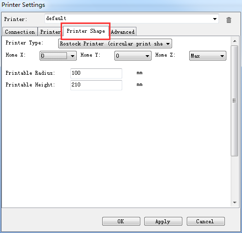
Choose printer shape. This is very important. Choose printer type as Rostock Printer(circular shape)
Home X: 0,
Home Y: 0
Home Z: Max
Printer Radius: 100mm
Printable height: 200mm
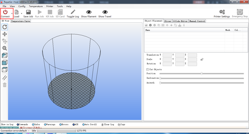
Step5. Hit "connect" in the upper left-hand corner. You should see the details of the connection in the console window in the bottom section of the screen.
Homing the printer
Homing is the first and foremostt hing you need to test. To home the printer, you can check if the three axis of the printer move in the same direction,if not, there will be crack for the spider and the carriage.
Before homing, you need to follow the next steps.
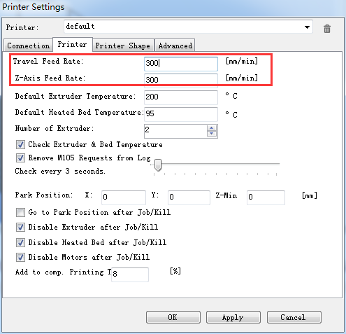
1.Go to printer setting> printer. Set the travel feed rate and the Z axis feed rate as 300 mm/min.
(Even though we have set the speed as slow as possible for you, you still need to adjust the feed rate. )
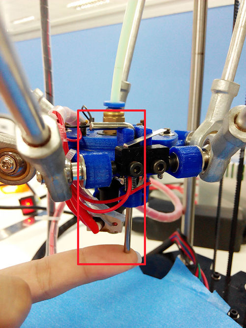
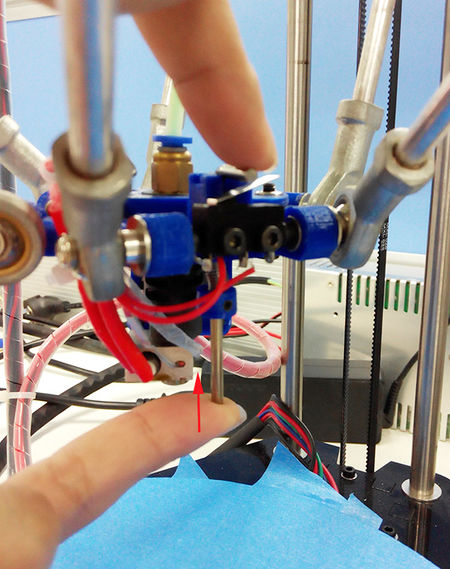
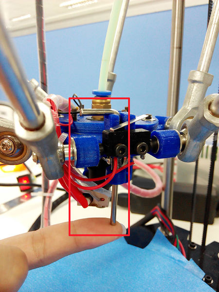
2.Hook up the probe with your hand, we are not testing the auto-leveling fuction right now.
3. Move the extruder head to the middle and be ready for emergency stop. You can click the emergency stop icon on the repetier host or shut the power supply directly.
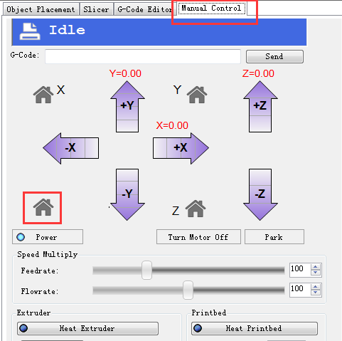
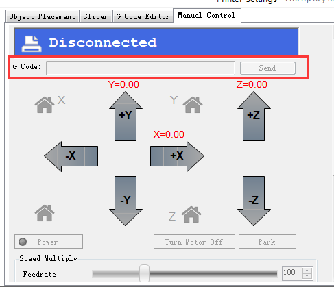
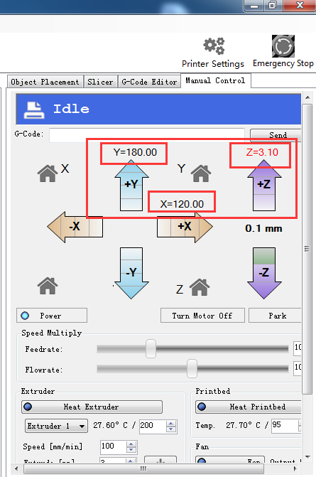
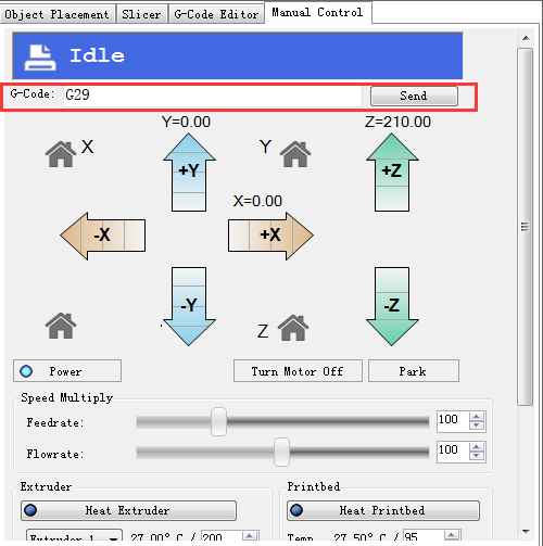
4. Go to the Manual Control and click the home icon.
If the three axis move in the different directions, please check the conenction of the stepper motor wires.
Define the initial Z axis height
If the printer can home normally, the three axis move in the same directions, we can set the height of the Z axis now, but this value may not be the final height.
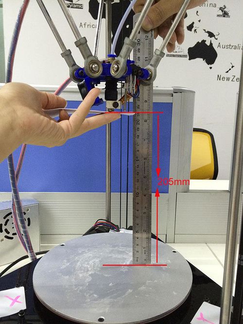
1. You can use a rule or digital graphics to measure. The height of the Z axis means the distance between the nozzle and the building platform after homing. So you need to measure after homing.
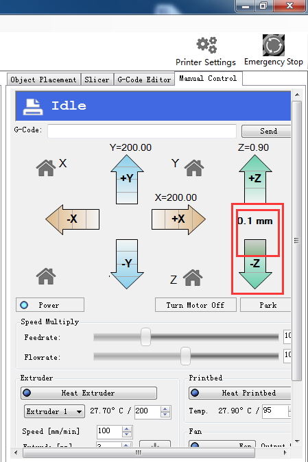
2. Or you can use maual control to move the Z axis down to the building platform till the nozzle just touches the bed. When moving the Z axis, please slow it down.
Move 0.1mm per click
3.Read the coordinates of the Z axis when the nozzle just touches the bed. E.g. if it is (0,0,1), then the Z axis height is 200-1=199。If it is (0,0,2) the height is 200-2=198.
(*200 is pre-set height in the firmware. 1 is the Z coordinate)
4. Open the firmware in IDE, locate the following code in IDE
//Manual homing switch locations:
- define MANUAL_HOME_POSITIONS // MANUAL_*_HOME_POS below will be used
// For deltabots this means top and center of the Cartesian print volume.
- define MANUAL_X_HOME_POS 0
- define MANUAL_Y_HOME_POS 0
- define MANUAL_Z_HOME_POS 200// For delta: Distance between nozzle and print surface after homing.
Then you can change the 200 into the height you got (e.g.205 or 199 you get) in the firmware and upload it.
Upon uploading the firmware, you need to change the printing setting in the Repetier host.
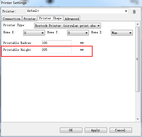
Choose printer shape. This is very important. Choose printer type as Rostock Printer(circular shape)
Home X: 0
Home Y: 0
Home Z: Max
Printer Radius: 100mm
Printable height: 205mm (* the height you put in the firmware)
Define the final Z axis height
Step1. Homeing the printer.
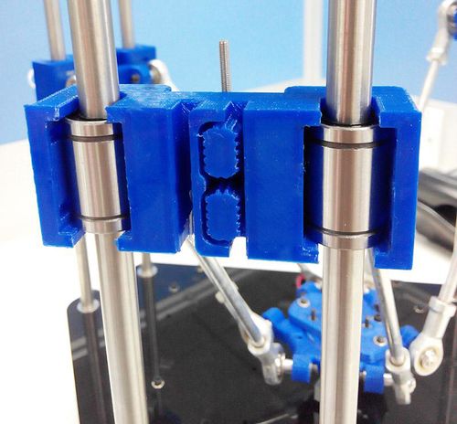
Step2. Tighten the screw trigger for each endstop, make sure they reach as long as possibl.
Adjust the screw on these 3 carridges.
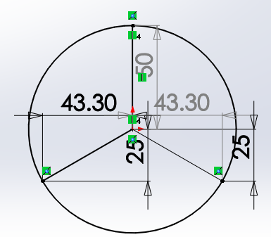
Step3. Set 3 probing points (0,50)、(43.3,-25)、(-43.3,-25), using G-code command to adjust the print head to the 3 points and record the distance between the nozzle and the print surface separately.
1)send command: G0 X0 Y50 Z2, record the distance;e.g. it is 3mm in my case.
2)send command: G0 X43.3 Y-25 Z2, record the distance;e.g. it is 2.7mm in my case.
3)send G 0 X-43.3 Y-25 Z2, record the distance;e.g. it is 2.2mm in my case.
You may need to adjust again and again till the three distance are the same or at least very close.
If the 3 numbers differ too much, you can manually move down the print head until the nozzle just hit the print bed, and screw the endstop screw trigger tightly. At this step, we are trying to adjust the distance between the nozzle and the print surface to keep the center point and its around point in one plain, that is to say, we need to make sure that when the nozzle touches the bed, whichever point it is, the Z Coordinate value should be the same, or almost the same.
You are required to operate again and again till you get a satisfied result.
if the screw has no room to adjust, you need to change the following setting later, record it. you need to modify the DELTA_RADIUS (For each 1.0 unit increase or reduce of the DELTA_RADIUS, the z printing volume will increase or reduce 0.2 unit)
#define DELTA_RADIUS (DELTA_SMOOTH_ROD_OFFSET-DELTA_EFFECTOR_OFFSET-DELTA_CARRIAGE_OFFSET+2.0)
- If the nozzle touches the center point but not the around points, that is a convex surface, you should reduce the DELTA_RADIUS from 2.0 to 1.0 for example.
- If the nozzle touches the around points but not the center point, that is a concave surface, you should increase the DELTA_RADIUS from 2.0 to 3.0 for example.
You may have to adjust this for many times to keep the center point and its around point in one plain. (the distance between the nozzle and the print bed). Modify it in the firmware and upload, test again,
So far, we can get the exact height of the Z axis.
check the status of endstop
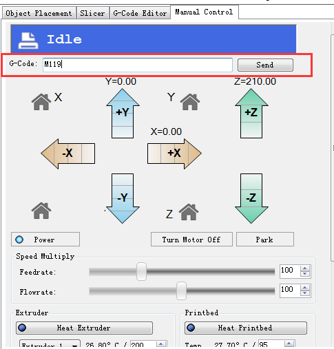
1. verify the endstop Before you risk any damage, you should test if you have configured the z-probe correctly. Send the command M119 to verify the endstop first.
You can see the following message
* x_max,y_max,z_max is for the endstop:
if the endstop is triggered, the feedback is Triggered;
If the endstop is not triggered, the feedback is Open.
z_min is for the probe:
When probe is put down, the feedback is Open;
When probe is hooked up, the feedback is Triggered;
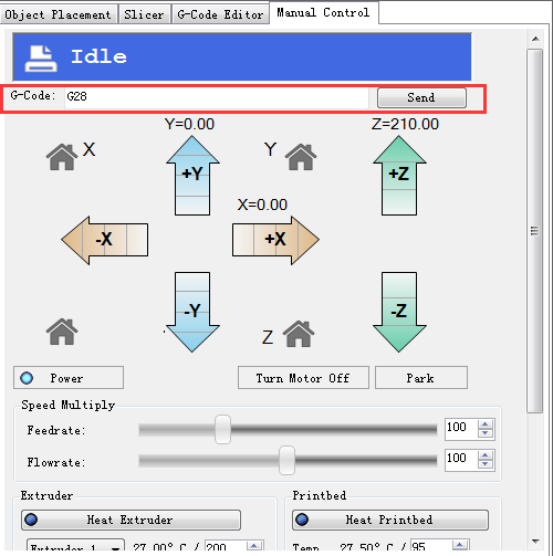
2. Verify Homing Send G28 or click the home icon to homing the printer.
You will see the X/Y/Z raise up till they hit the endstops. Then they will move down a bit and hit the endstops again before they stop (that is to increase the printing precision).
Trouble shooting:
The axis did not stop after hitting the endstops.
Please check if the wire connection of the endstops of X/Y/Z axis matches.
Note: unlike other machines, the origin here is not (0,0,0) but (0,0,MANUAL_Z_HOME_POS)
Define the Z_PROBE_OFFSET
You can calculate the Z_PROBE_OFFSET values with this procedure: Put down the prob. Manual y move the print head down slowly, place the probe at the center of the print bed. When you hear the trigger of the endstop, you can get the coordinate on the Repetier host. In my case, it is 【-20.35,11.75,0.3】, you can add it to the following settings.
#define X_PROBE_OFFSET_FROM_EXTRUDER 20.35
#define Y_PROBE_OFFSET_FROM_EXTRUDER -11.75
#define Z_PROBE_OFFSET_FROM_EXTRUDER -0.3
//these are the offsets to the probe relative to the extruder tip (Hotend - Probe), these values are very important, especially the Z_PROBE_OFFSET.
Then modify the Z_PROBE_OFFSET in the firmware and upload again.
slic3r configuration
printer setting
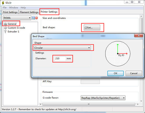
1. set bed shape.
in the latest version of Slic3r,V1.2.7, you can set the bed shape, this is very important when printing with your delta rostock mini. go to general manual, click set button, choose circular and fill in the diameter of the printer bed.
- if your slic3r is not the latest version, you can update or download it here, unzip the file and drag them into the directory of your previour slic3r directory. do please delete the old version. Restart your Repetier and continue.
2.Start G29 Command
Thoughg we have added an auto-leveling probe for the Rostock mini, but generally there is no G-gode in the sli3er, so we need to add the G29 command to the sli3er.
Step1. Start G29 command in Slic3r.
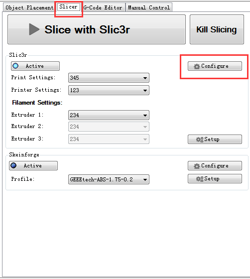
Click Slicer and configure, waiting for a minute till the slicer window prompt up.
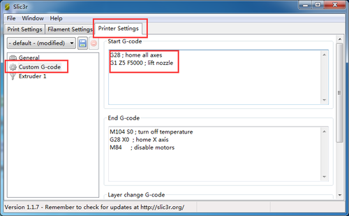
Step2. Choose printer setting-- Custom G-code.
You can see from the start G-code, there is no G29.
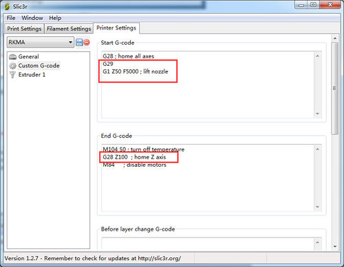
So you need to add the G29 after G28 to start it. And change Z5 into Z50.
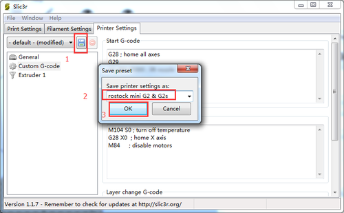
Save the current printing setting, click “OK” to continue.
In case any cratch caused to your print bed, do not rush to test the auto-leveling command right now.
Calibration of auto-leveling
Auto-leveling probe is controlled by G29 command. As this is a DIY 3d printer, you may need to help it complete the leveling:
1.You need to put down the auto-leveling probe manualy.
2.Send G29 command.
3.auto-leveling probe will probe the 3 pre-setted probing points. After probing, the print head will raise up a bit and stop.
4.Hook up the probe manualy.
as this calibration needs to be done several time before you can start printing, you can refer to this guide.
1.Manualy put down the probe, then send M119 command to check if the Z-min is open.
2.Send G28 command to auto home the printer.
3.Send G29 command to start the auto-leveling. *there might be collisions, please always be ready to cut off the power supply.
4.After sending G29, the printing head will move down, and hit the probe point setted, after the probing, the printing head will go up.
5.After the leveling, the printing head will raise up and stop, meaning the leveling is finished. You should have the probe back (as the spring on the probe is a bit tight, to make it easier, you can use your finger to push up the probe).
6.Send G1X0 Y0 command to move the printing head to(0,0).
7.Click -Z icon on manual control to move the print head down until it touches the print bed just enough. Send M114 command to get the present coordinates. If the coordinate is (0,0,0), the auto-leveling is successful. If not, you need to modify the Z_PROBE_OFFSET_FROM_EXTRUDER , e.g. Reduce -0.3 to -0.5, and then re-upload the firmware and test again.
8.You may have to test it for more than once, but for the sake of better printing object,please be patient.
9.Once auto-leveling is set up, Hook up the probe manualy. Then you can print your first prints.
