Difference between revisions of "HM-TRLR-S Series 100mW LoRa Transceiver"
(→Node ID) |
(→Default setting) |
||
| (9 intermediate revisions by the same user not shown) | |||
| Line 1: | Line 1: | ||
=Introduction= | =Introduction= | ||
| − | [[File:433,915transceiver.jpg| | + | [[File:433,915transceiver.jpg|300px||thumb| 433,915transceiver ]] |
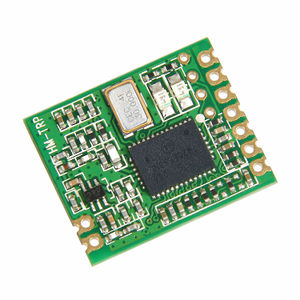
HM-TRLR-S series is a low cost, high performance transparent transceiver operating at 433/915MHz. It is LoRa/FSK/GFSK/OOK modulation variety. It features small size, high output power, high sensitivity, long transmission distance and most of the parameters can be set via the command. Receive and send data to automatically switch. Use generic UART interface. It is easy to realize the wireless data transmission if provided with the UART data. It is flexible for the users to set the parameters of UART baud rate, output power, data rate, frequency select, modulation mode select etc. It is your ideal choice for designing wireless data transmission products which can be widely used on wireless data transmission field. | HM-TRLR-S series is a low cost, high performance transparent transceiver operating at 433/915MHz. It is LoRa/FSK/GFSK/OOK modulation variety. It features small size, high output power, high sensitivity, long transmission distance and most of the parameters can be set via the command. Receive and send data to automatically switch. Use generic UART interface. It is easy to realize the wireless data transmission if provided with the UART data. It is flexible for the users to set the parameters of UART baud rate, output power, data rate, frequency select, modulation mode select etc. It is your ideal choice for designing wireless data transmission products which can be widely used on wireless data transmission field. | ||
| Line 85: | Line 85: | ||
[[File:Dimension1.png|400px|]] | [[File:Dimension1.png|400px|]] | ||
| − | |||
| − | |||
=Application Part= | =Application Part= | ||
| Line 339: | Line 337: | ||
[[File:Parameter Table10.png]] | [[File:Parameter Table10.png]] | ||
| − | + | ===LoRa transmission frequency bandwidth selection command=== | |
When the module is working in LoRa mode, the transmitting signal bandwidth can be set according to the needs of the module, the wider the bandwidth is, the faster the air rate will be. | When the module is working in LoRa mode, the transmitting signal bandwidth can be set according to the needs of the module, the wider the bandwidth is, the faster the air rate will be. | ||
| Line 346: | Line 344: | ||
[[File:AT LRSBW Command.png]] | [[File:AT LRSBW Command.png]] | ||
| + | |||
| + | Parameter Table | ||
| + | |||
| + | [[File:Parameter Table16.png]] | ||
| + | |||
| + | ===LoRa spreading factor selection command=== | ||
| + | When the module is working in LoRa Mode, the spreading factor can be set according to the needs of module, the higher the spreading factor is, the higher the reception sensitivity will be, and the slower the speed will be. | ||
| + | |||
| + | AT+LRSF (SpreadingFactor) Command | ||
| + | |||
| + | [[File:AT LRSF Command.png]] | ||
| + | |||
| + | Parameter Table | ||
| + | |||
| + | [[File:Parameter Table11.png]] | ||
| + | |||
| + | ===LoRa Pre-error -correction -code selection command=== | ||
| + | When the module is working in LoRa mode, data transmission adopts the pre- error-correction –coding- format; this command is set by choosing its Coding Rate. | ||
| + | |||
| + | AT+LRCR (CodingRate) Command | ||
| + | |||
| + | [[File:AT LRCR Command.png]] | ||
| + | |||
| + | Parameter Table | ||
| + | |||
| + | [[File:Parameter Table12.png]] | ||
| + | |||
| + | ===LoRa hopping frequency allowed command=== | ||
| + | When the module is working in LoRa mode, frequency hopping function is allowed. | ||
| + | |||
| + | AT+LRHF (HFSS) Command | ||
| + | |||
| + | [[File:AT LRHF Command.png]] | ||
| + | |||
| + | Parameter Table | ||
| + | |||
| + | [[File:Parameter Table13.png]] | ||
| + | |||
| + | ===LoRa Payload length setting command=== | ||
| + | When the module is working in LoRa mode, data is transmitted in batches, this command is used to set the packetlength. | ||
| + | |||
| + | AT+LRPL (PacketLenth) Command | ||
| + | |||
| + | [[File:AT LRPL Command.png]] | ||
| + | |||
| + | Parameter Table | ||
| + | |||
| + | [[File:Parameter Table14.png]] | ||
| + | |||
| + | ===LoRa hopping frequency cycle command=== | ||
| + | |||
| + | When the module is working in LoRa Mode, you can set the cycle of hopping frequency. | ||
| + | |||
| + | AT+LRHPV (HoppingPeriodValue) Command | ||
| + | |||
| + | [[File:ATLRHPVCommand.png]] | ||
| + | |||
| + | Parameter Table | ||
| + | |||
| + | [[File:Parameter Table15.png]] | ||
| + | |||
| + | ===LoRa hopping frequency stepping command=== | ||
| + | When the module is working in LoRa Mode, you can set the stepping of hopping frequency. | ||
| + | |||
| + | AT+LRFSV (FrequencyStepValue) Command | ||
| + | |||
| + | [[File:AT LRFSV Command.png]] | ||
| + | |||
| + | Parameter Table | ||
| + | |||
| + | [[File:Parameter Table17.png]] | ||
| + | |||
| + | ===Mode Command=== | ||
| + | This command can change the modulation mode of HM-TRLR | ||
| + | |||
| + | AT+MODE Command | ||
| + | |||
| + | [[File:AT MODE Command.png]] | ||
| + | |||
| + | Parameter Table | ||
| + | |||
| + | [[File:Parameter Table18.png]] | ||
| + | |||
| + | ===Frequency Band Command=== | ||
| + | This command can change the working frequency band of HM-TRLR. | ||
| + | |||
| + | AT+BAND Command | ||
| + | |||
| + | [[File:ATBAND Command.png]] | ||
| + | |||
| + | Parameter Table | ||
| + | |||
| + | [[File:Parameter Table19.png]] | ||
| + | |||
| + | ===Test Command=== | ||
| + | Connection test | ||
| + | |||
| + | AT Command | ||
| + | |||
| + | [[File:AT Command.png]] | ||
| + | |||
| + | |||
| + | ===Save parameters=== | ||
| + | When parameters changes with the AT commands, HM-TRLR will not save the parameters to the Flash Memory automatically, HM-TRLR will read the parameters Flash Memory after reset. Therefore it is necessary for the user to save the new parameter values; you can use this command to write the parameters changed previously in Flash Memory. | ||
| + | Warning: Due to the time of writing Flash memory is limited, Flash Memory may be damaged if you keep rewriting, and you can rewrite no more than10000 times. | ||
| + | |||
| + | AT&W Command | ||
| + | |||
| + | [[File:AT W Command.png]] | ||
| + | |||
| + | |||
| + | ===Default setting=== | ||
| + | *HM-TRLR-S-433 the default value of the module | ||
| + | |||
| + | [[File:Default setting.png]] | ||
| + | |||
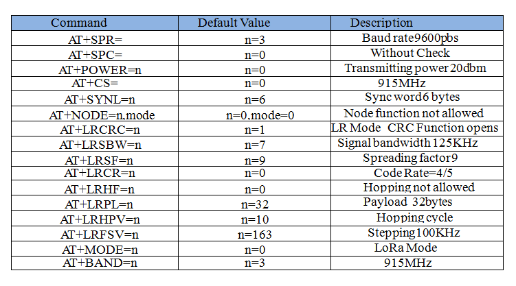
| + | *HM-TRLR-S-915 The default value of the module | ||
| + | |||
| + | [[File:Default value.png]] | ||
| + | |||
| + | |||
| + | |||
| + | == How to get it == | ||
| + | Click here to buy: http://www.geeetech.com/hmtrlrs-series-100mw-lora-transceiver-p-881.html | ||
Latest revision as of 03:24, 25 October 2014
Contents
- 1 Introduction
- 2 Application Part
- 3 HM-TRLR-S AT Instruction Manual
- 3.1 Overview
- 3.2 Command Syntax
- 3.3 Command Type
- 3.3.1 Baud Rate Command
- 3.3.2 Serial check mode command
- 3.3.3 Transmit power command
- 3.3.4 The selection of Communication Channel
- 3.3.5 Set up Sync Word
- 3.3.6 Set up Sync Word Length
- 3.3.7 Node Function
- 3.3.8 Node ID
- 3.3.9 Broadcast ID
- 3.3.10 LoRa CRC allows command
- 3.3.11 LoRa transmission frequency bandwidth selection command
- 3.3.12 LoRa spreading factor selection command
- 3.3.13 LoRa Pre-error -correction -code selection command
- 3.3.14 LoRa hopping frequency allowed command
- 3.3.15 LoRa Payload length setting command
- 3.3.16 LoRa hopping frequency cycle command
- 3.3.17 LoRa hopping frequency stepping command
- 3.3.18 Mode Command
- 3.3.19 Frequency Band Command
- 3.3.20 Test Command
- 3.3.21 Save parameters
- 3.3.22 Default setting
- 3.4 How to get it
Introduction
HM-TRLR-S series is a low cost, high performance transparent transceiver operating at 433/915MHz. It is LoRa/FSK/GFSK/OOK modulation variety. It features small size, high output power, high sensitivity, long transmission distance and most of the parameters can be set via the command. Receive and send data to automatically switch. Use generic UART interface. It is easy to realize the wireless data transmission if provided with the UART data. It is flexible for the users to set the parameters of UART baud rate, output power, data rate, frequency select, modulation mode select etc. It is your ideal choice for designing wireless data transmission products which can be widely used on wireless data transmission field.
Features
- Low cost, high performance, high reliability
- LoRa/FSK/GFSK/OOK modulation, 2-way half –duplex communication, strong anti-interfere
- 433/915MHz ISM band, globally license free.
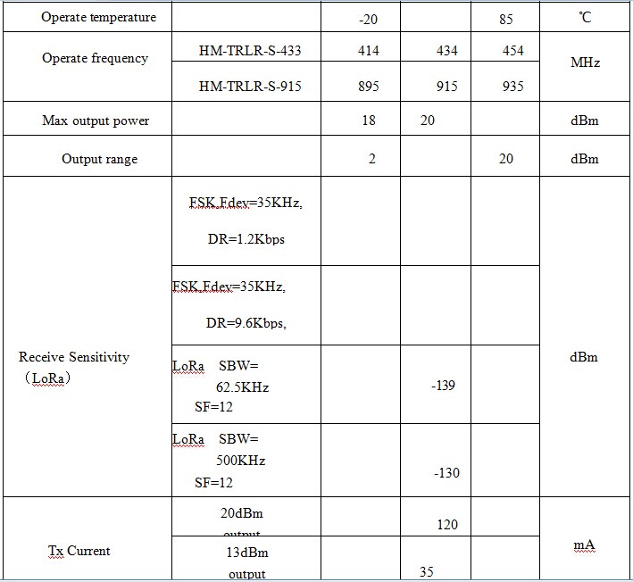
- Maximal output power100mW(20dBm), output power adjustable between 2-20dBm
- LORA Sensitivity -139dBm
- Supply current for Tx 130mA@20dBm, 35mA@13dBm
- Supply current for Rx 16mA
- Low current sleep mode 2uA
- Standard UART interface, extendable to RS232 or other interface
- Operation frequency can be configured, acceptable for several modules working in different frequency with no disturbance on each other.
- RF parameters as needed, users can be modulated by software.
- Easily use, auto exchange on communication & transceiver
- Communication speed 1.2kbps -115.2kbps,can be modulated through software
- Afford Sleep control signal,user self control work duty cycle
- With LED indicator
- Longer transmission distance,over 5Km in open air
- Small size 16*20*2mm,10PIN SMD package,easy for assembly .
- Tuning free
- Accord FCC, ETSI standard
Applications
- Remote control, remote measurement
- Data collection
- Wireless meter
- Access control
- IT household appliance
- Intelligence household appliance
- Identification system
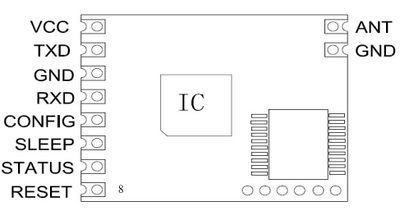
Pin Description
VCC—— Power supply,2.4-3.6V DC power, recommendation 3.3V DC power
TXD—— Data transmission
GND—— Ground
RXD—— Data receiving
CONFIG——Set low for configuration mode, while set high for communication
SLEEP——Set low for normal mode for data transceiver , while back to sleep if set high
STATUS——Disconnected
RESET——Reset trigger input, Active low
ANT—— Input/output interface with 50 ohm antenna
GND—— Ground
Maximum Specification
Parameters
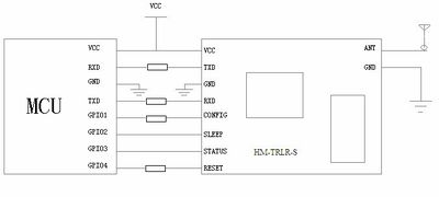
Typical Application
HM-TRLR-S TTL UART
As in the above Figure, connect the TXD pin of HM-TRLR-S with UART RXD Pin of MCU, connect the RXD pin of HM- TRLR-S with the UART TXD pin of MCU. Then the CONFIG/SLEEP/RESET/STATUS of HM-TRLR-S connects with GPIO of MCU.
HM-TRLR-S extends to RS232
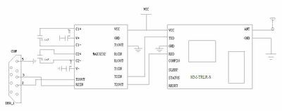
You can extend the HM-TRLR-S to RS232 by adding the MAX3232, and then you can directly connect the COM to the PC.
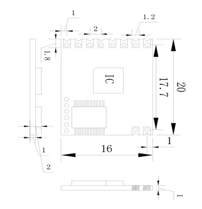
Mechanical Dimension
unit:mm
Application Part
Modulation Mode
HM-TRLR series transparent transceiver module can work in the traditional FSK / GFSK modulation mode, as well as in LoRa modulation mode. According to the application requirements, users can switch the modulation mode conveniently. Using principles: use FSK / GFSK modulation when requiring large quantities of high-rate data transmission; use the LoRa modulation when long-distance data transmission is needed.
Operating Mode
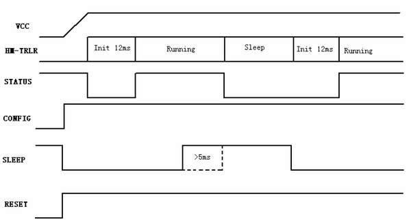
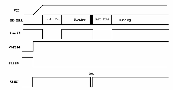
HM-TRLR series transparent transceiver module has three kinds of operating mode: Running Mode、Configuration Mode and Sleep Mode. When the module is in Running Mode, users can send and receive data; when the module is in the Configuration Mode, users can change the formulation parameters according to the need via AT commands; Sleep Mode allows the module to enter into a low power consumption status.
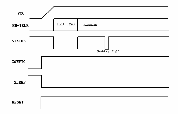
- Running Mode Timing Diagram
Note:When the modulation pattern is LoRa and the HM - TRLR receive buffer is full, the STATUS pin will output a low level.
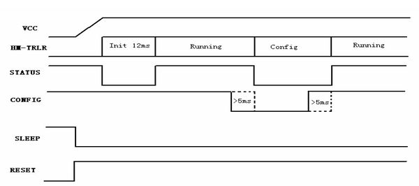
- Configuration Mode Timing Diagram
Note:The module enters into the Configuration Mode by pulling up the CONFIG pin. If the STATUS output is at low level, users can send AT commands to revise the parameters.
- Sleep Mode Timing Diagram
Note: Sleep mode is controlled by SLEEP pin
- Reset Timing Diagram
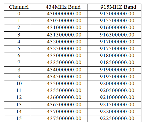
Channel Frequency
Different model of HM-TRLR module has different frequency band, each frequency band is divided into 16 channels, and frequency details are as below:
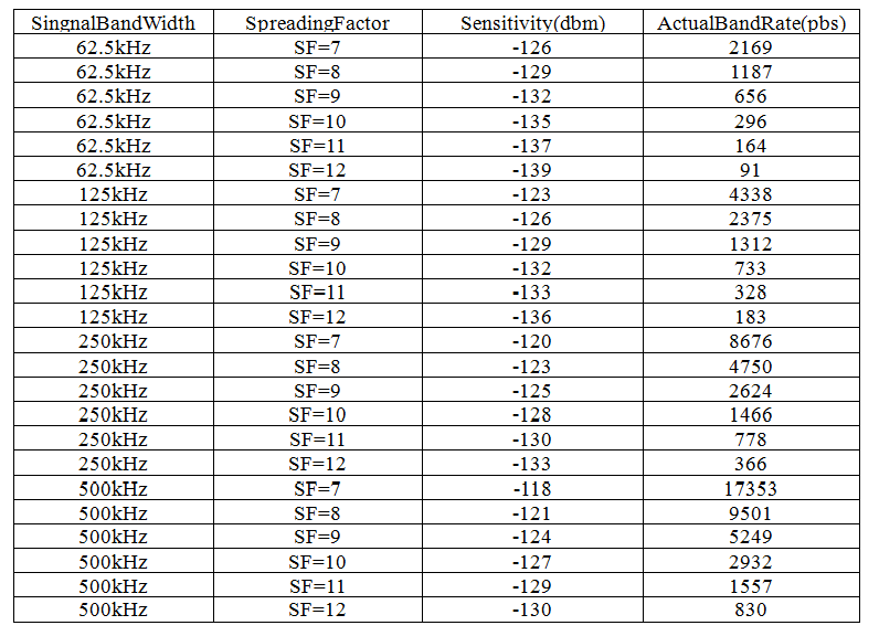
Transfer rate
When HM-TRLR module works in FSK modulation, the air rate can self-adapt to serial baud rate. Theoretically, it is able to transfer wireless data, it’s better to transmit in batches to avoid interference in the air if the data package is large. When HM-TRLR module works in LoRa modulation, the transmission rate depends on the Signal Bandwidth, the Spreading Factor, FEC coding rate and the Payload Length. The sensitivity of receiver is only related to the Signal Bandwidth and the Spreading Factor. The following table shows the relationship between the transmission rate and parameters:
Test conditions:
1. Supply voltage = 3.3 V
2. Temperature = 25° C
3. CRC on payload enabled
4. Payload length = 64 bytes
5. Coding Rate = 1
Hopping Frequency Spread Spectrum (HFSS)
When HM-TRLR module works in LoRa modulation, it has the function of HFSS, which can be applied to the occasions where the time of frequency occupancy is limited. For example, in the United States, the frequency of the ISM segments 902-928, when the data transmission time of a packet exceeds the frequency occupancy time limits, you can use frequency-hopping technology, there are two parameters need to be set: Hopping Cycle and Frequency Stepping.
Calculating Formula:
HoppingPeriod(ms) = ( 2SF/BW) * FreqHoppingValue
SF = SpreadingFactor
BW = SingnalBandWidth
FreqHoppingValue = 1~255
FreqStep = 61Hz*FreqStepValue
FreqStepValue = 0~65535
Node ID Function with FSK
When HM-TRLR works in FSK modulation, you can set the Node ID, when the function of the Node ID is turned on, the first byte the transmitter sends is the Node ID of the receiver, and the receiver receives only the Node ID that matches with it. When the function of Node ID is turned on, the module can start the Broadcast ID function; when the Broadcast starts, the receiver can receive data both from the Node ID and the Broadcast.
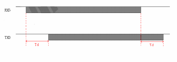
Note:When this function is on, the interval between the two frames of data is not less than the Td; the first byte of each frame of data is the Node ID or Broadcast ID.
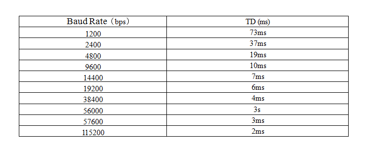
Td (Time Delay)
TD for FSK modulation
Td is the delay of time between module 1(RXD pin received data) and module 2 (TXD pin transfer data). The time delay (Td) will change with different baud rate, as shown below:
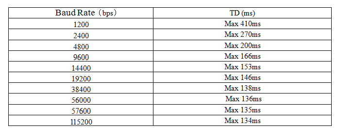
Td for LoRa Modulation
As air data is transmitted in batches when the module is in LoRa Modulation, if the data exceeds Payload Length and the air rate is less than serial rate, the data receivered will be intermittent. In the transmitter, you can check whether the HM-TRLR buffer is full or not through the STATUS pin.
Air rate is higher than the serial rate, as shown below:
Air rate is less than the rate of the serial rate, as shown below:
Testing Conditions:
1. Spread Factor = 9
2. Singal Band Width = 250 kHz
3. Code Rate = 1
4. PayLoad = 32 bytes
HM-TRLR-S AT Instruction Manual
Overview
When IO port is triggered by peripherals, the HM-TRLR-S module will enter into the Configuration Mode, you can revise the performance parameter by sending AT commands through serial ports.
Command Syntax
Command will be represented by capitalized ASCII and ending with <CR>, when the module receives the commands, it will interpret and respond to commands
Command Set Format
Command Set is used to set the parameters of peripherals for HM-TRLR-S transparent transceiver module; it is begins with capital AT, followed by the command type and parameters.
  Command Format:AT+Cmd Type=Para1, Para2…<CR>
  Command Return Succeed:  OK<CR>
  Command Return Failed:  ERROR: n<CR>
Read Command Format
Read Command is used to read the command of peripherals for HM-TRLR-S transparent transceiver module; it begins with capital AT, and followed by the command type and a question mark.
  Command Format:AT+CmdType=? <CR>
  Command Return Succeed:  CmdType: Para1, Para2…<CR>
  Command Return Failed:  ERROR: m<CR>
Parameter interpretation when an error returns
When an execution error is returned, the modules will return ERROR:m.
Command Type
Baud Rate Command
Serial baud rate refers to the communication rate between the module and its peripherals, when the setup is complete, the new baud rate takes effect immediately, and the baud rate of the peripherals should be based on the new module communication.
AT+SPR (SerialPortRate) Command
Parameters Table
Serial check mode command
Modules and peripherals using UART mode, their check mode can be set, when the setup is completed, the new formulation will come into effect immediately.
AT+SPC(SerialPortCheck) Command
Parameters Table
Transmit power command
Transmitting power can be revised, when the setup is completed, it will come into effect when you exit the Configuration Mode.
AT+POWER Command
Parameters Table
The selection of Communication Channel
Channel selection means the frequency point that RF (Radio Frequency) works, there are 16 channels available, and only modules with the same channel can communicate between each other.
Parameters Table
Set up Sync Word
Module Sync word can be set with1 to 8 bytes, and the modules with the different Sync Words can’t communicate with each other.
AT+SYNW Command
Parameters Table
Example 1: If the Sync Word is 0x12,0x34,0xAB, 0xEF, that is 4 byte, and the transmitting AT Command is “AT+SYNW=1234ABEF\r\n”.
Set up Sync Word Length
Module Sync word can be set with1 to 8 bytes, and the modules with the different Sync Words can’t communicate with each other. It is suggested to set more than 2 bytes, when it is set as 0, there will be no Sync Word.
AT+SYNL Command
Parameters Table
Node Function
In FSK Mode, you can set the Node Function for the module
AT+NODE Command
Parameters Table
Node ID
In FSK Mode, you can set the number of Node ID of the module.
AT+NID Command
Parameters Table
Broadcast ID
In FSK mode, you can set the number of Broadcast ID of the module.
AT+BID Command
Parameters Table
LoRa CRC allows command
Opens Air Data transmission or closes CRC
AT+LR Command
LoRa transmission frequency bandwidth selection command
When the module is working in LoRa mode, the transmitting signal bandwidth can be set according to the needs of the module, the wider the bandwidth is, the faster the air rate will be.
AT+LRSBW(SignalBandWidth) Command
Parameter Table
LoRa spreading factor selection command
When the module is working in LoRa Mode, the spreading factor can be set according to the needs of module, the higher the spreading factor is, the higher the reception sensitivity will be, and the slower the speed will be.
AT+LRSF (SpreadingFactor) Command
Parameter Table
LoRa Pre-error -correction -code selection command
When the module is working in LoRa mode, data transmission adopts the pre- error-correction –coding- format; this command is set by choosing its Coding Rate.
AT+LRCR (CodingRate) Command
Parameter Table
LoRa hopping frequency allowed command
When the module is working in LoRa mode, frequency hopping function is allowed.
AT+LRHF (HFSS) Command
Parameter Table
LoRa Payload length setting command
When the module is working in LoRa mode, data is transmitted in batches, this command is used to set the packetlength.
AT+LRPL (PacketLenth) Command
Parameter Table
LoRa hopping frequency cycle command
When the module is working in LoRa Mode, you can set the cycle of hopping frequency.
AT+LRHPV (HoppingPeriodValue) Command
Parameter Table
LoRa hopping frequency stepping command
When the module is working in LoRa Mode, you can set the stepping of hopping frequency.
AT+LRFSV (FrequencyStepValue) Command
Parameter Table
Mode Command
This command can change the modulation mode of HM-TRLR
AT+MODE Command
Parameter Table
Frequency Band Command
This command can change the working frequency band of HM-TRLR.
AT+BAND Command
Parameter Table
Test Command
Connection test
AT Command
Save parameters
When parameters changes with the AT commands, HM-TRLR will not save the parameters to the Flash Memory automatically, HM-TRLR will read the parameters Flash Memory after reset. Therefore it is necessary for the user to save the new parameter values; you can use this command to write the parameters changed previously in Flash Memory. Warning: Due to the time of writing Flash memory is limited, Flash Memory may be damaged if you keep rewriting, and you can rewrite no more than10000 times.
AT&W Command
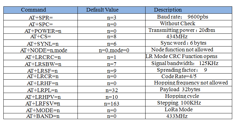
Default setting
- HM-TRLR-S-433 the default value of the module
- HM-TRLR-S-915 The default value of the module
How to get it
Click here to buy: http://www.geeetech.com/hmtrlrs-series-100mw-lora-transceiver-p-881.html
