Difference between revisions of "Arduino joystick"
(→Introduction) |
|||
| (9 intermediate revisions by the same user not shown) | |||
| Line 1: | Line 1: | ||
| + | ==Introduction== | ||
Getting started with Arduino joystick module | Getting started with Arduino joystick module | ||
| Line 5: | Line 6: | ||
No matter who you are, a learner or an engineer, you can use it to achieve your creative desire.Making a string of led flicker for a set period of time is quite a good project for the beginners to learn how it functions. But here we do another small experiment as a beginning in which we can read the 3-axis dimensions from a ps2 joystick module in console by USB serial port.<br> | No matter who you are, a learner or an engineer, you can use it to achieve your creative desire.Making a string of led flicker for a set period of time is quite a good project for the beginners to learn how it functions. But here we do another small experiment as a beginning in which we can read the 3-axis dimensions from a ps2 joystick module in console by USB serial port.<br> | ||
| − | All we need is a joystick module, some jumper wires and most important Arduino UNO which is a great starter Arduino, it provides a solid foundation for those just getting started. We can connect the module to the Arduino board according to the photo below.<br> | + | [[File:Joystick1.jpg]][[File:Uno.jpg]] |
| + | |||
| + | All we need is a [http://www.geeetech.com/joystick-module-for-arduino-sensor-shield-p-434.html joystick module],some jumper wires and most important [http://www.geeetech.com/arduino-uno-328-p-173.html Arduino UNO] which is a great starter Arduino, it provides a solid foundation for those just getting started. We can connect the module to the Arduino board according to the photo below.<br> | ||
As the joystick is moved in any direction, X port and Y port on the joystick board ouput X and Y dimension of analog signal as voltage whose value is in the range of 0 to 5V, the Readanalog() command can convert the analog value to digital value in the range of 0 to 1023. Z port on joystick board output Z dimension of digital signal when pressed. So X port and Y port of the joystick need to be connected to the analog input pin0 and pin1 on UNO respectively. Z port needs to be connected to the digital pin7.<br> | As the joystick is moved in any direction, X port and Y port on the joystick board ouput X and Y dimension of analog signal as voltage whose value is in the range of 0 to 5V, the Readanalog() command can convert the analog value to digital value in the range of 0 to 1023. Z port on joystick board output Z dimension of digital signal when pressed. So X port and Y port of the joystick need to be connected to the analog input pin0 and pin1 on UNO respectively. Z port needs to be connected to the digital pin7.<br> | ||
| + | |||
| + | [[File:Joystick2.jpg]] | ||
X, Y and Z dimension input to the computer is by means of USB port. Now we can upload and click the serial monitor later to see what’s going on, X,Y and Z dimension from joystick module is showing up in the monitor constantly.<br> | X, Y and Z dimension input to the computer is by means of USB port. Now we can upload and click the serial monitor later to see what’s going on, X,Y and Z dimension from joystick module is showing up in the monitor constantly.<br> | ||
| Line 13: | Line 18: | ||
Serial.begin(9600) command means that we setup Arduino with the transfer rate, in the case 9600bits per second. Please notice the board and serial port should be correctly selected in tools menu. And the baud rate we select in monitor must be the same as the baud in the code above, otherwise the monitor would show a series of messy codes<br> | Serial.begin(9600) command means that we setup Arduino with the transfer rate, in the case 9600bits per second. Please notice the board and serial port should be correctly selected in tools menu. And the baud rate we select in monitor must be the same as the baud in the code above, otherwise the monitor would show a series of messy codes<br> | ||
| + | [[File:Serial.jpg]] | ||
| − | + | ==Relating code== | |
int sensorPin = 7; | int sensorPin = 7; | ||
int value = 0; | int value = 0; | ||
| − | |||
void setup() { | void setup() { | ||
pinMode(sensorPin, OUTPUT); | pinMode(sensorPin, OUTPUT); | ||
| Line 27: | Line 32: | ||
Serial.print(“X:”); | Serial.print(“X:”); | ||
Serial.print(value, DEC); | Serial.print(value, DEC); | ||
| − | |||
value = analogRead(1); | value = analogRead(1); | ||
Serial.print(” | Y:”); | Serial.print(” | Y:”); | ||
Serial.print(value, DEC); | Serial.print(value, DEC); | ||
| − | |||
value = digitalRead(sensorPin); | value = digitalRead(sensorPin); | ||
| − | |||
Serial.println(value, DEC); | Serial.println(value, DEC); | ||
Serial.print(” | Z: “); | Serial.print(” | Z: “); | ||
delay(300); | delay(300); | ||
} | } | ||
Latest revision as of 08:35, 2 March 2012
Introduction
Getting started with Arduino joystick module
This is the first time I come into contact with Arduino, which is an open-source electrics platform based on flexible, easy-to-use hardware and software. As a beginner to these stuffs which can perform so many useful functions is a fascinating matter. Arduino also has an open-source software which is similar to C Language.
No matter who you are, a learner or an engineer, you can use it to achieve your creative desire.Making a string of led flicker for a set period of time is quite a good project for the beginners to learn how it functions. But here we do another small experiment as a beginning in which we can read the 3-axis dimensions from a ps2 joystick module in console by USB serial port.
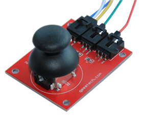
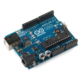
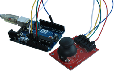
All we need is a joystick module,some jumper wires and most important Arduino UNO which is a great starter Arduino, it provides a solid foundation for those just getting started. We can connect the module to the Arduino board according to the photo below.
As the joystick is moved in any direction, X port and Y port on the joystick board ouput X and Y dimension of analog signal as voltage whose value is in the range of 0 to 5V, the Readanalog() command can convert the analog value to digital value in the range of 0 to 1023. Z port on joystick board output Z dimension of digital signal when pressed. So X port and Y port of the joystick need to be connected to the analog input pin0 and pin1 on UNO respectively. Z port needs to be connected to the digital pin7.
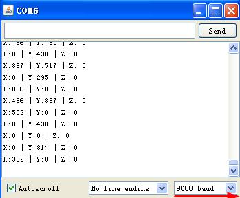
X, Y and Z dimension input to the computer is by means of USB port. Now we can upload and click the serial monitor later to see what’s going on, X,Y and Z dimension from joystick module is showing up in the monitor constantly.
Serial.begin(9600) command means that we setup Arduino with the transfer rate, in the case 9600bits per second. Please notice the board and serial port should be correctly selected in tools menu. And the baud rate we select in monitor must be the same as the baud in the code above, otherwise the monitor would show a series of messy codes
Relating code
int sensorPin = 7;
int value = 0;
void setup() {
pinMode(sensorPin, OUTPUT);
Serial.begin(9600);
}
void loop() {
value = analogRead(0);
Serial.print(“X:”);
Serial.print(value, DEC);
value = analogRead(1);
Serial.print(” | Y:”);
Serial.print(value, DEC);
value = digitalRead(sensorPin);
Serial.println(value, DEC);
Serial.print(” | Z: “);
delay(300);
}


