Difference between revisions of "Iduino MEGA R3"
(→The Interface Resource Instruction) |
(→Software Resource) |
||
| Line 52: | Line 52: | ||
==Software Resource== | ==Software Resource== | ||
| − | Arduino 1.0.1 | + | [http://www.geeetech.com/wiki/images/0/03/Arduino-1.0.1.zip Arduino 1.0.1] |
==Data Resource== | ==Data Resource== | ||
Revision as of 08:43, 16 October 2014
Contents
Introduction
overview
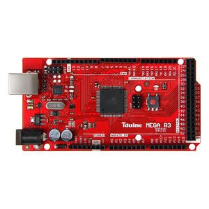
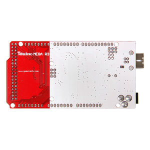
As with our Iduino Mega 2560, the Iduino MEGA R3 is also a microcontroller board based on the ATmega2560. It has 54 digital input/output pins (of which 14 can be used as PWM outputs), 16 analog inputs, 4 UARTs (hardware serial ports), a 16 MHz crystal oscillator, a USB connection, an external power jack, an ICSP header, and a reset button, enabling the board to be plug-and-play. The Iduino MEGA R3 differs from Iduino Mega 2560 in that it has 3 additional pins, they are SDA, SCL and IOREF,amoung which the IOREF pin can provide the VREF to the board. In addition, considering the compatibility of Iduino MEGA R3 with the series products to come,Iduino MEGA R3 has a port reserved on the left side of IOREF pin.
Interfaces specifications
- Microcontroller:ATmega2560
- Input Voltage (recommended): 7-12V
- Operating Voltage: 5V
- 54 Digital I/O Pins:(of which 14 provide PWM output)
- 16 Analog Input
- 4 UART (hardware serial ports)
- An USB interface
- An ICSP header
- A power interface
- A reset button
- DC Current of I/O Pin: 40 mA
- DC Current for 3.3V Pin: 50mA
- Flash Memory: 256KB of which 8KB is used for bootloader ( Atmega 328)
- SRAM: 8KB
- EEPROM: 4 KB
- Clock Speed: 16MHz
- Product Weight:34g
- Dimensions:102mm*54mm*11mm
Software Resource
Data Resource
ATmega2560 Data Book
Interface Resource
The Interface Layout
The Interface Resource Instruction
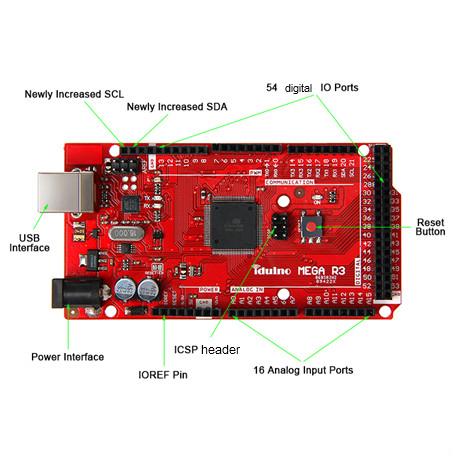
Power Interface: 7-12 V,supply power for the entire board, note that higher voltage may cause damage to the chip.
54 digital IO ports: use pinMode (), digitalWrite () and digitalRead () function to manipulate, each IO can be used as input and output ports, the operating voltage is 5V, the output of each channel can provide or receive a maximum current of 40mA and Each channel is configured with a 20-50K ohm internal pull-up resistor (disconnected by default).
In addition, some pins have the following specific functions:
4 serial ports:Serial port 0---0(RX) and 1(TX); serial port 1---19(RX) and 18(TX); serial port 2---17(RX) and 16(TX); serial port 3---15(RX) and 14(TX). Pins 0 and 1are connected to the corresponding pins of the ATmega16U2 USB-to-TTL Serial chip, used to receive (RX) and transmit (TX) TTL serial data.
6 external interrupts: 2 (interrupt 0), 3 (interrupt 1), 18 (interrupt 5), 19 (interrupt 4), 20 (interrupt 3) and 21 (Interrupt 2). These pins can be configured to trigger an interrupt on a low value, a rising or falling edge, or a change in value.
14 PWM (0--13): Provide 14 8-bit PWM output with the analogWrite() function.
SPI (53 (SS), 51 (MOSI), 50 (MISO), 52 (SCK)): support SPI communication.
LED(pin 13):a pin specially reserved for Iduino to test the LED When the pin is HIGH value, the LED is on, when the pin is LOW, it's off.
ICSP header:The ICSP header is composed of 6 pins. Usually used to upload Bootloader(You can complete the connection between PC and board with our product USB Tiny OTP Writer)
16 Analog input ports:Each of which can convert the analog input into 10 bits of resolution digital input (i.e. 0-1023 different values). By default they measure from ground to 5 volts, but it is possible to change the upper limit of their range using the AREF pin and analogReference() function.
Besides, some pins have other specific functions: TWI interfaces (20 (SDA) and 21 (SCL); new SDA and SCL): Support communications interface (compatible with I2C bus).
USB Interface: This interface is used to load the main program or connected with external USB devices.
IOREF: This pin is used to provide the operating reference voltage of the microcontroller on Iduino.
Development Environment setting
Interface Connecting and Setting
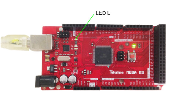
If you want to load or test the program of Iduino Mega R3, just connect the Iduino Mega R3 with computer with a USB cable, as shown below:
Get Started
Connect the Iduino Mega R3 to computer with a USB cable.
Please refer to the documentation first:Arduino_IDE Simple instructions for use_.doc, open the Test code:File—Examples—Digital—BlinkWithoutDelay
When the program is loaded, after the Arduino 1.0.1 appears the following interface, the firmware is loaded successfully, then the LED L of Iduino Mega R3 will blink every second.
FAQ
USB can’ t be identified, a yellow exclamation mark will be shown in Device Manager, as shown below:
Solutions are as follow:
In the [Device Manager], right-click [Arduino Mega 2560], in the dialog box, select the [Update device of driver software], select [Browse my computer for driver software]
Open the software installation directory of Arduino IDE, copy the directory folder [drivers] to the corresponding directory (as shown), and then click Next, the driver installation is completed.


