Difference between revisions of "Raspberry Pi Model B+"
(→Documents) |
|||
| Line 115: | Line 115: | ||
Datasheet:[[Media:Raspberry Pi Model B+ datasheet.pdf]] | Datasheet:[[Media:Raspberry Pi Model B+ datasheet.pdf]] | ||
| + | |||
| + | |||
| + | |||
| + | == How to buy == | ||
| + | Click here to buy: http://www.geeetech.com/raspberry-pi-model-b-p-853.html | ||
Latest revision as of 05:37, 11 September 2014
Contents
Description
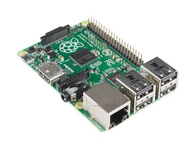
Raspberry pie is a portable, powerful,and mini computer. The board length is only 85mm and width is only 56mm.Its size only as big as a credit card but it is a capable little PC. It can be used for many of the things that your desktop PC does, like high-definition video, spreadsheets, word-processing, games and more. Raspberry Pi also has more wide application range, such as music machines, parent detectors to weather stations, tweeting birdhouses with infra-red cameras, lightweight web server, home automation server, etc. It enables people of all ages to explore computing, learn to program and understand how computers work. The Raspberry Pi Model B+ provides more GPIO, more USB than Model B. It also improves power consumption, audio circuit and SD card. It is more useful for embedded projects.
Compare with Model B
The Model B+ is the higher-spec variant of the Raspberry Pi. Compared to the Model B it has:
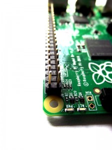
- More GPIO. The GPIO header has grown to 40 pins, while retaining the same pinout for the first 26 pins as the Model B.
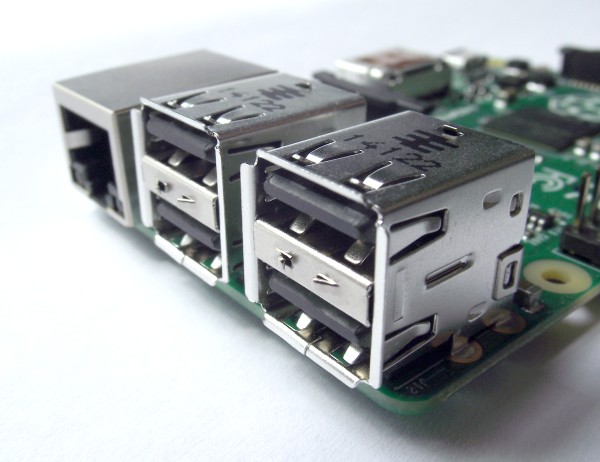
- More USB. We now have 4 USB 2.0 ports, compared to 2 on the Model B, and better hot plug and over current behavior.
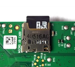
- Micro SD. The old friction-fit SD card socket has been replaced with a much nicer push-push micro SD version.
- Lower power consumption. By replacing linear regulators with switching ones we’ve reduced power consumption by between 0.5W and 1W.
- Better audio. The audio circuit incorporates a dedicated low-noise power supply.
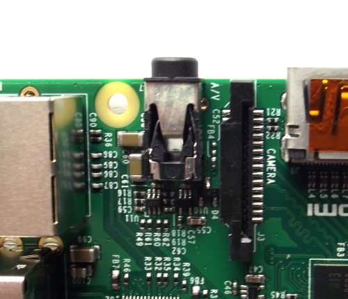
- Neater form factor. We’ve aligned the USB connectors with the board edge, moved composite video onto the 3.5mm jack, and added four squarely-placed mounting holes.
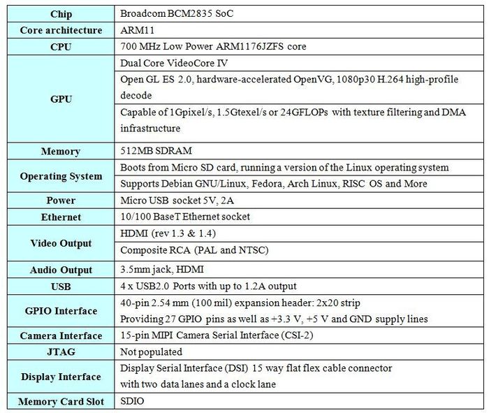
Specifications
Dimensions
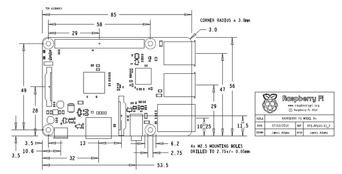
85mm x 56mm x 17mm
Includes
- Raspberry Pi Model B+ Board x1
- Instruction card x1
Mechanical Schematic
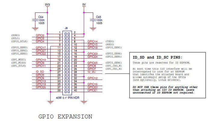
Connectors Schematic
Detail look
- Audio
The sound output from the original model B is generally considered something of a joke. If you need reasonable quality audio, you have to use an external sound card. The Raspberry Pi (like almost all computers) is digital. It process information in 1s and 0s, or high and low voltages. However, sound waves are analogue. That means that they vary across a whole spectrum rather than just flipping between two states. The model B had no problem processing the digital sound, however the digital-to-analogue converter (DAC) was prone to adding noise into the output that wasn’t supposed to be there. The reason for this is that on the model B, there was a 3.3 volt supply that powered several components on the board, one of which was the DAC. If one of the other components drew current from the 3.3 volt line while sound was playing, it could cause the power supply to fluctuate slightly, and this fluctuation caused distortion to the analogue output. On the B+, the DAC has its own power supply from the new regulator, which means there’s nothing else to make the current fluctuate and therefore the sound output is much better. There are also some other minor changes to the audio processing to make it perform better. Serious audiophiles may still want additional audio hardware, but the Pi’s sound output should now be good enough for most people.
- USB
The most obvious improvement in the B+ is the addition of two more USB 2 ports, bringing the total up to four. Without the improved regulator, these wouldn’t have been very useful since there wouldn’t have been enough power to run many peripherals. However, we found that we could run most USB peripherals. We tried to overload it with a mouse, keyboard, USB webcam and memory stick and it still worked. We even had some success with a keyboard, mouse, webcam and microphone, though we wouldn’t recommend that setup for any serious recording. For normal use of the Pi (such as with mouse, keyboard and USB memory stick), the ports should work without any problems.
- GPIO
After the additional USB ports, the most noticeable thing on the B+ is the additional GPIO headers. There are now 40 rather than 26 (there are actually 34 on the B, but the 8 on pad 5 don’t have headers). These provide 19 GPIOs (including pad 5) on the B and 26 on the B+. In technical terms, the whole of Bank 0 from the SoC is now exposed (and the other banks are put to work elsewhere). The first 20 of the 40 headers on the B+ are the same as the B, so some existing expansion boards should work without problems. However, because the board layout has changed, larger expansion boards that fit around the components may not fit on anymore. For example, the PiFace doesn’t. This is something that schools and workshops that already have a significant number of expansion boards may wish to consider. Since the headers just need raising to lift the expansion board above the level of the components on the board, it’s quite likely that someone will start selling adaptors for this. The additional 7 GPIOs probably won’t have much effect on most projects since expansion boards tend to use one of the GPIO communications protocol (i2C or SPI) and these only use a few pins. If you need more GPIOs, it’s fairly trivial to use one of these protocols to drive more, and this will provide some protection for the pins on the Raspberry Pi as well. There are also no more feature pins in the GPIO, so don’t expect any more PWMs or UARTs. One area where the extra pins could come in useful is in implementing communication protocols that need more channels. For example, the model B doesn’t have enough pins to run either DPI or SLI (protocols to communicate with displays), but the B+ does. This won’t actually be supported by the Raspberry Pi Foundation, but will, in theory, be possible should someone implement it. Hopefully we’ll see some interesting expansion boards that take advantage of the new possibilities soon.
- Smaller Tweaks
The analogue video is now combined with the audio jack into an single AV port. There are now four mounting holes, and they’re in a rectangle which makes them a little more useful. The USB ports no longer overhang the PCB by much (it’s now the same as the Ethernet), which should make it a little easier to make cases for the board, or fit it inside embedded devices. Perhaps the biggest of the little changes is the SD card switching from full size to micro. As well as being smaller, the new card holder feels more secure. While we’ve never came across a Pi with a broken SD card slot, the old ones never felt sturdy to us. Despite their smaller size, microSD cards come in the same capacities as full size ones (and usually for about the same prices). Other than the size, there’s no difference between them. In fact, in our testing, we used exactly the same micro SD card in the Model B as the B+, we just put it in an adaptor when using it with the B. As long as you have the latest version of Raspbian (version 1.3.9 or higher), everything should work.
The only issue we had with the new card holder is that it is now a click in – click out style. The first time we picked up our Model B+ while it was running, we placed one finger on the SD card and another on the opposite side of the Pi (we got used to picking our old Pi up in this way). Instead of securing the SD card in place like this did on the Model B, this pushed in the microSD and clicked it, and as soon as we put it down, the card popped out. This isn’t a huge problem, just something to be aware of. The board also gets a few aesthetic improvements. It now has rounded corners, and more importantly, most of the connectors are now marked. The camera and (as yet unused) display connector are labelled. It’s a minor improvement that will make it a little easier for newcomers. We were able to run our test Pi in the turbo overclocking setting without problems. This is something we haven’t had much luck with on Model B’s in the past (although we have heard of plenty of people whose Pis have performed well at this setting). We’ve only been sent one B+ to test, so we obviously can’t extrapolate and say that the B+ performs better in this regard. If they do, it’ll be a welcome performance improvement for many people.
Design Case
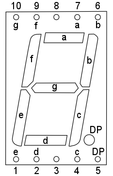
I really like 7 segment LED displays, because of their simplicity and their “retro” look, so I decided to use the expanded GPIO port to directly control a number of seven segment LED displays, without the need for additional driver IC (or having to multiplex individual elements or characters). Rather confusingly perhaps, each “seven segment” LED display actually has 8 terminals plus a common terminal. Seven of the terminals control the seven segments of the display and the eighth is connected to the decimal point. I used common cathode seven segment displays (RS part number 588-639) so that I could connect the Raspberry Pi’s GPIO pins directly to the input terminals and connect the common cathode terminal of each display to ground via a single 47 Ohm current limiting resistor. The pinout of the seven segment displays I used is shown below.
Each pin is connected to the segment of the display as indicated by the letter next to the pin, so for example, pin 1 is connected to segment “e”. Pins 3 and 8 are the common cathode pins and either one may be used. I wanted to use the seven segment displays to display some useful information, so I thought it would be fun to connect a 1 wire temperature sensor (DS18B20, RS part number 540-2805) to the Raspberry Pi model B+ to measure the ambient temperature.
- Building the Circuit
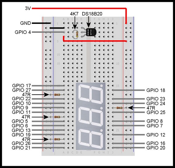
The DS18B20 1-wire temperature sensor will (by default) use GPIO 4 as an input. I decided not to use GPIO 2 or GPIO 3, because of the pull-up resistors connected to them, and also decided not to use GPIO 14 and GPIO 15 because they double up as the UART interface (which is enabled by default), and it’s often useful to connect to the Raspberry Pi in console mode using the serial interface. This left me with 21 available GPIO pins – just enough to connect three seven segment LED display modules (ignoring the decimal point “segments”). The finished circuit is shown below as built on a small breadboard, with all connections to the new Raspberry Pi model B+ GPIO pins as indicated.
The three 47 Ohm resistors on the left hand side are the current limiting resistors for each seven segment LED display, and the 47 Ohm resistor on the right hand side causes the decimal point on the middle seven segment LED display to be permanently illuminated. The DS18B20 1-wire temperature sensor is shown at the top of the breadboard and only requires one 4.7K Ohm resistor to function properly.
- Setting up the Raspberry Pi
To enable kernel support for the DS18B20 1-wire temperature sensor, open the file “/etc/modules” and add the following two lines to the end of the file:
w1-gpio w1-therm
There are various ways you can do this but the simplest is to enter the following command at the command line prompt:
sudo nano /etc/modules
This will open the file in nano where you can add the extra lines and then save the file and exit by pressing Ctrl+X, Y and finally Enter
You will need to reboot your Raspberry Pi model B+ for the changes to take effect. You can do this by entering the following command at the command line prompt:
sudo reboot
When your Raspberry Pi model B+ has rebooted, log in and the then enter the following command at the command line prompt:
cd /sys/bus/w1/devices
Now enter “ls” at the command line prompt. You should see something similar to the following:
28-000004d0963d w1_bus_master1
Make a note of the long string of numbers and letters – this is the serial number of your DS18B20 temperature sensor and you will need it retrieve data from the sensor (your serial number will be different to the one shown above).
- Writing the Software
I have written a Python3 program to take a temperature measurement (in deg C) every second and display the measured temperature in the format “##.#” on the three seven segment LED modules connected to the GPIO header on the new Raspberry Pi model B+. The program is designed to display the measured temperature as long as it is in the range -9.9 deg C to 99.9 deg C. Outside this range the LED display will show “EEE”.
- Putting it all Together
Run the program from the command line prompt by entering the following (where “xx-xxxxxxxxxxxx” is the serial number of your DS18B20 temperature sensor):
sudo python3 rpi_thermometer.py xx-xxxxxxxxxxxx
After a short delay, the temperature will be displayed on the LED display modules. Press Ctrl+C to terminate the program.
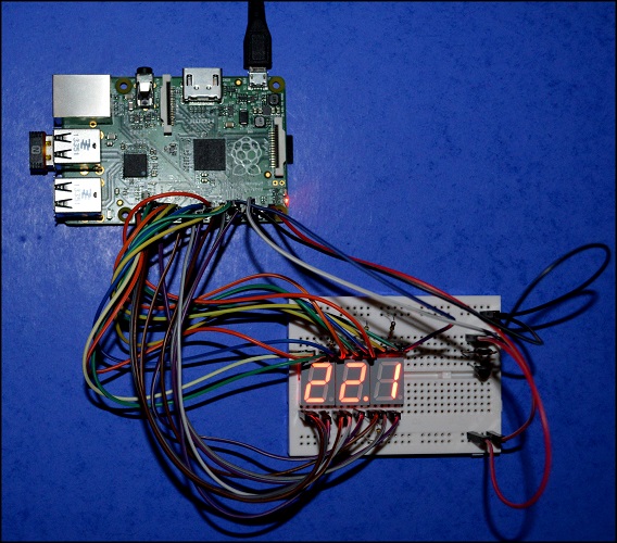
The whole setup can be made a lot more portable (as shown in the photo below) by connecting a WiFi adapter to the Raspberry Pi model B+ and then connecting using SSH from another computer to access the Raspberry Pi and run the software.
Documents
Connectors Schematic:Media:Raspberry Pi B+ IO Connectors Schematic.pdf
Mechanical Schematic:Media:Raspberry Pi B+ Mechanical Schematic.pdf
Datasheet:Media:Raspberry Pi Model B+ datasheet.pdf
How to buy
Click here to buy: http://www.geeetech.com/raspberry-pi-model-b-p-853.html
