Difference between revisions of "Generation 6 Electronics"
(→How to buy) |
(→Were to get) |
||
| Line 326: | Line 326: | ||
==Were to get== | ==Were to get== | ||
| − | + | Here you can get one [http://www.geeetech.com/generation-6-electronics-gen6-p-677.html Generation 6 Electronics] | |
Revision as of 01:37, 28 August 2014
Contents
Introduction
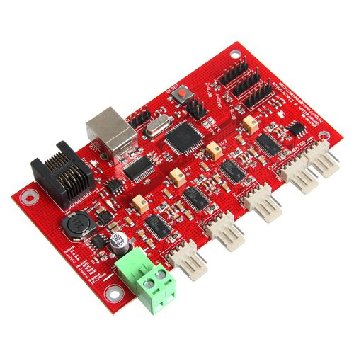
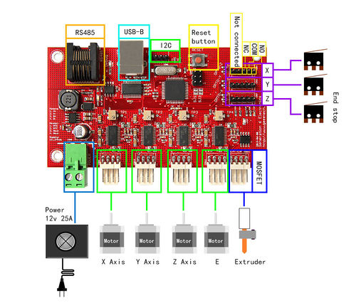
Generation 6 is designed especially for 3D printer of FFF/FDM (Fused Deposition Modeling). The majority of the components on board adapt SMT, with much small surface mount component,smaking the whole layout more concise. As opposed to Generation 7 which is designed to be printed on a Mendel(among other design goals).The main board adapts the design of RS232, with integrated hardware for driving one extruder (stepper, heater and thermistor), adapts ATmege 644p chip, the input voltage is 12-24VDC.
Another major difference with other Gen6 electronics is that they use Texas Instruments DRV8811 chips to drive the stepper motors. This means they require firmware modifications from the normal Polulu-based electronics which use Allegro A4983 chips.
Benefits of this Design
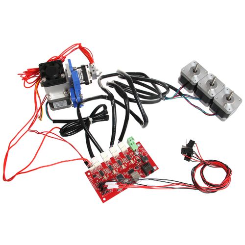
- These electronics are a single board solution, so you don't need all those cables and one thick sheet and 4 reprap parts less.
the bottom thick sheet (big one) doesn't add much rigidity, the front one is used for stiffness of the frame, not the bottom one.
- It has a standard USB connection (USB A>B cable needed)
- It uses micro-stepping (1/8) for quieter operation.
- It is cheaper than for example Makerbot's version of the RepRap Generation 3 electronics.
- It uses small standard Molex connectors for motors, heater, and optos.
- The pcb of the optos are integrated, so you only need the optos on cables with 5way Molex connectors
Hardware Features
- on-board USB-RS232 convertor
- Integrated hardware for driving one extruder (stepper, heater and thermistor)
- RS485 bus connector with the possibility to link through the extruder step and dir signals
- Integrated hardware for driving H21LOB or TCST2103 slotted optosensors
- High input voltage range: 12-24Vdc
- Use of standard connectors with easy and clean installation
- Debug LEDs for power, communication and heater output
- Reset button
Specifications
- Dimensions 110x60mm
- Mounting grid: 100x50mm (4x M3)
- Input voltage 12-24Vdc
- On-board controller: ATmega 644p (Atmel Corp.)
- RS485 connector: RJ45
- Heat output: MOSFET output, 4A
- Thermistors input: 100K thermistor
Power
A modified PC Power supply will work fine. If you would prefer a power brick or 'wall wart' for the power supply 50W should be enough, but 60W is recommended.
The design uses a Euro-style plug and connector, so just strip the wire ends and screw them in place. The board has a + and - label on it, and it's a good idea to use a marker to draw a + and - on the connector plug as well. 0V should go in the - and the other wire in the +.
About the input voltage: 12-24Volts is possible, but the nichrome wire length needs to be changed also if input voltage is not 12V!
please make sure to double check (i.e. CHECK IT TWICE) power input + and - when you connect it to your board.
USB
- One (1) USB A>B cable
Plug it into the board (B end), turn on the power, and plug the into the computer (A end). Windows should auto-detect the USB to serial interface and install the required drivers. If not, Download and install the drivers from here.
The 12V supply must be on for the USB to be active. The board will not run on computer power alone, even for programming.
End-Stop Sensors
Opto-endstop
The firmware sees a missing endstop as a tripped endstop. If you want to test your steppers prior to installing the endstops you still need to plug the endstops into the Gen6 board.
Without any endstops installed the stock firmware will refuse to move each axis in the direction that would be toward the endstop.
Inverting Optos Gen6 was originally designed for H21LOB optos. Header pinout for H21LOB optos is as follows:
- - Emitter Anode(E+)
- - Emitter Cathode (E-)
- - Detector Vcc (D+)
- - Detector Vo (D-)
- - Detector Ground (Gnd)
Non-Inverting Optos H21LOB optos have been discontinued. TCST2103 is a suitable replacement. Header pinout for TCST2103 optos is as follows:
- - Emitter Anode(E+)
- - Emitter Cathode(E-)
- - No Connection
- - Detector Vcc (D+)
- - Detector Vo (D-)
Mating Connector Part Numbers
- Three (3) 5 wire Molex housing, 2.54 mm, friction ramp, polarized (2659 series, Molex part# 0022013057)
- Fifteen (15) Molex crimp terminals (2759 series, Molex part# 0008550101)
Microswitches
From 17-Dec-2010 Mendel-Parts changed the type of opto-end stops from inverting to non-inverting, so depending on which version opto's your firmware is configured for, you will need to wire the microswitches differently. Microswitch Wiring for Inverting Firmware (prior to 17-Dec-2010)
A typical microswitch connection would be:
- - No Connection
- - No Connection
- - Switch NC
- - Switch Common
- - Switch NO
Microswitch Wiring for Non-Inverting Firmware (after 17-Dec-2010) A typical microswitch connection would be:
- - No Connection
- - No Connection
- - Switch NO
- - Switch Common
- - Switch NC
Hall-Θ
The Hall-Θ board is marked (from left to right) : 5v / Gnd / Stop
For inverting firmware (or replacing a H21LOB) :
- No Connection
- No Connection
- +5v
- Stop
- Gnd
For non-inverting firmware (or replacing a TCST2103) :
- No Connection
- No Connection
- Gnd
- Stop
- +5v
Heater and Thermistor
- One (1) 4 wire Molex housing, 2.54 mm, friction ramp, polarized (KK series, Molex part# 0022013047)
- Four (4) Molex crimp terminals (2759 series, Molex part# 0008550101)
Pinouts listed on the PCB:
- NTC (Brown)
- NTC (Black)
- Heat (Yellow)
- Heat (Clear or gray)
Pin 1 is furthest from the power connector and closest to the edge of the board, Pin 4 is closest to the power connector.
Heated Bed
Gen6 doesn't support a heated bed as-is. If you want to connect one, you need an external switch like the SevenSwitch (for 12V heated beds) or a solid state relay (for 110V/220V heat mats).
Stepper Motors for X, Y, Z Axes and Extruder
- Four (4) 4 wire molex housing, 2.54 mm, friction ramp, polarized (KK series, Molex part# 0022013047)
- Sixteen (16) Molex crimp terminals (2759 series, Molex part# 0008550101)
Wire lengths listed by [User:Camiel|Camiel] are as follows:
- Two (2) @ 40 cm (X & E)
- Two (2) @ 75 cm (Y & Z)
Pinouts listed on the PCB
- A+ = A
- A- = B
- B+ = C
- B- = D
Adjusting the Stepper Current
The stepper motor current is set by the tiny trim pots next to each stepper driver (the chips with the heat sinks). An exposed pad next to each trim pot lets you measure the reference voltage. The test points are labelled TP1 for X through TP4 for E. Place the black multimeter probe on one of the gold squares around the mounting holes. Place the red probe on the test point. The peak motor current is 0.57 times the test point voltage. My board came pre-adjusted to approximately 2V (the indicator pips on the adjustment screw point at the test point) which equals about 1.14A.
Development Environment setting
Interface Connecting and Setting
File Burning
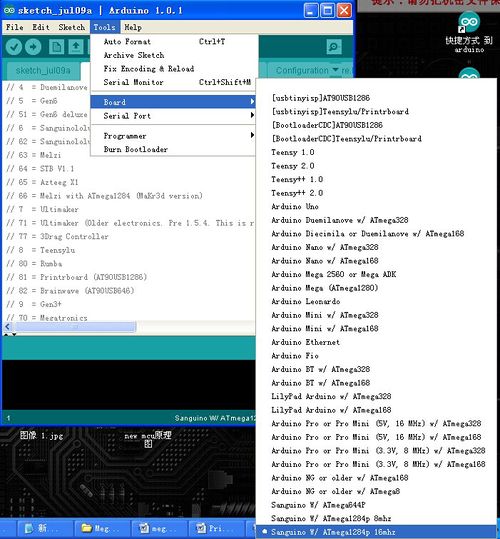
Arduino IDE 1.Windows users need install driver before uploading. The board: Tools > Board > sanguino W/ATMEGA644P 16, as shown below.
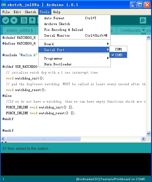
Configuring serial interface: Tools > Serial Port > the corresponding COM Port of Generation 6 is usually the last one. As shown below:
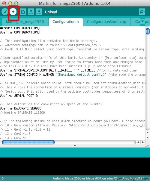
Click![]() to check if it is right and then click
to check if it is right and then click![]() to upload firmware, as shown below
to upload firmware, as shown below
Upon uploading, IDE will display the rate of progress; when done uploading appears, the uploading process succeeded
After uploading, you can go on to the next step. If you cannot upload, check the dialog box below to identify the problem and solve it. The common mistakes are the wrong select of type of board or serial
Software Setting
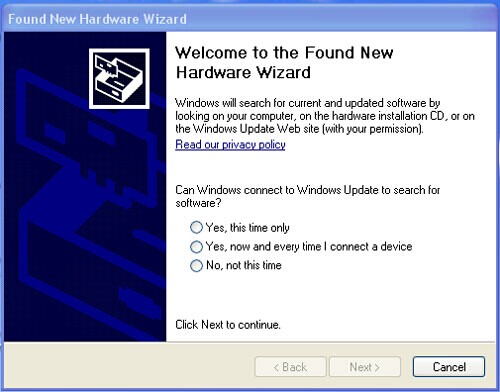
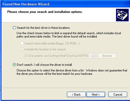
Arduino IDE Installation 1.Windows will prompt that a new USB device, named FT232R USB UART was found when connecting USB with generation to the PC. Then, windows will open the dialog box “found new hardware wizard”, check “no, not this time”, then click “next” to continue.
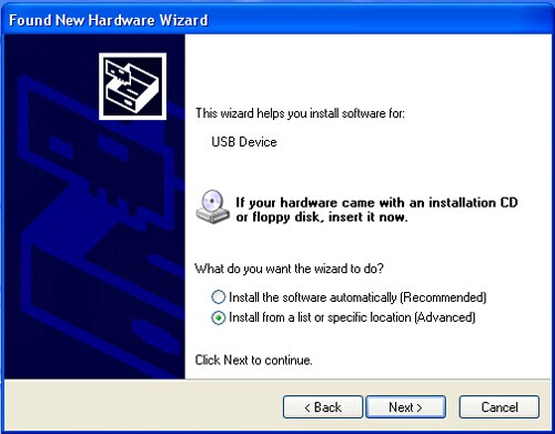
Check “install from a list or specific location (advanced)”, then click “next”.
Specify “drivers” in Arduino 1.0.installation directory to install driver.
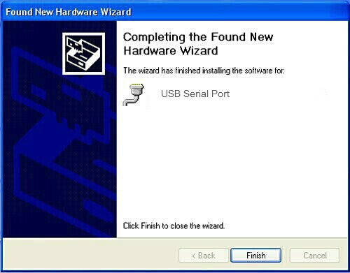
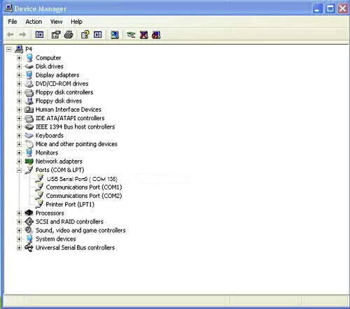
If everything goes well, windows will install the corresponding driver. After the installation complete. You can find the corresponding Generation 6device in device manager of windows.
Now, you can find the corresponding Generation 6device in device manager of windows.
Get Started
Generation 6 is the CPU of a 3D printer, manipulating the whole process of printing. Generation 6 can‘t be put in use directly without uploading firmware.
1. Firmware uploading- marlin.
2. Setting parameters of the firmware
The parameters that need setting are as below, for those not mentioned just leave them as default.
#define BAUDRATE 250000
This parameter is for the baud rate of serial port. Note: a successful communication can be realized only when the Baud rate of upper computer is identical with that of Firmware. The Baud rate is not set in random. The common Baud rate are: 2400,9600,19200,38400,57600,115200,250000. The last three are frequently used for 3D Printer.
#define MOTHERBOARD 5
This parameter is set for board type. 3D Printer has many types of main board, and the settings of IOs are different, therefore, the parameter has to correspond to the type of your board, or it can’t operate normally. The parameter of Generation 6should be 5 (single- nozzle). For other board, you can refer to the annotation on the board.
 #define TEMP_SENSOR_0 3
 #define TEMP_SENSOR_BED 3
The two parameters are set for the type of temperature sensor respectively. They are the critical parameter to check if the sensor read temperature correctly. The printer can’t operate normally, even has potential risk (damage the device and even worse). You must modify depending on the temperature sensor you use.
#define EXTRUDE_MINTEMP 170
This parameter is set to avoid potential risks when the extruder operates before reaching the rated temperature. If you use other 3D Printer, such as printer to make Chocolates, 45℃ is appropriate, so that the parameter configured to a lower value(such as 40℃).
 const bool X_ENDSTOPS_INVERTING = true;
 const bool Y_ENDSTOPS_INVERTING = true;
 const bool Z_ENDSTOPS_INVERTING = true.
The three parameters are set for the end stops of three axes. If the configuration is true, the end stop outputs 1 in default condition, and outputs 0 when triggered. That is to say, mechanical end stop should connect to the NO (normally open) contactor. If it is connected to the NC (normally closed), true should be changed to false.
 #define INVERT_X_DIR false
 #define INVERT_Y_DIR true
Mistakes are often made in the above two parameters. The parameters are different for different machinery. In principle, the origin should be at lower-left corner of the print platform (origin: [0, 0]), or at up-right corner (origin: [max, max]). Only in this way will the printing be correct, otherwise, the printing is the mirror image of one axis which is not what expected.
 #define X_HOME_DIR -1
 #define Y_HOME_DIR -1
 #define Z_HOME_DIR -1
If the position of the origin is the minimum, the parameter is -1; if it is the maximum, the parameter is 1.
 #define X_MAX_POS 205
 #define X_MIN_POS 0
 #define Y_MAX_POS 205
 #define Y_MIN_POS 0
 #define Z_MAX_POS 200
 #define Z_MIN_POS 0
These parameters are crucial to the printing size. Fill in parameters by reference to the coordinate graphs. It is important to note that the origin is not the printing center and the real printing center usually lies at [(x.max - x.min)/2, (y.max -y.min/2)]. The coordinate of central will be used in the slice tool. The printing center’s coordinate must correspond to the parameter configuration, or it will print to the outside of the platform.
#define HOMING_FEEDRATE {50*60, 50*60, 4*60, 0}
The parameter means the homing speeds (mm/min). This parameter can be set as default if you use the x-axis and y-axis adopt synchronous belt drive and z-axis adopts screw drive.
#define DEFAULT_AXIS_STEPS_PER_UNIT {85.3333, 85.3333, 2560, 158.8308}
FAQS
1. Common Configuration Modifications The configuration of the firmware is controlled by defines in configuration.h. This file has options for supporting several different boards and Mendel options. When you change a define, search for the name and make sure you are changing the right one. The top of the file sets MOTHERBOARD to 2 (which later sets MENDEL) and defines GEN6 so look for those #ifdefs to know which setting to change.
- If you are experiencing pauses (the print head pauses for multiple seconds) you might want to try increasing the baud rate setting HOST_BAUD to 38400 or 250000.
- If one of your axes goes in the wrong direction toggle INVERT_X_DIR (substitute Y, Z as needed) by changing it from 1 to 0 (or back). Search for GRUB_PULLEYS to get the right set of defines.
- If the scale of one of your axes is wrong adjust X_STEPS_PER_MM (or Y or Z). There are tutorials on this you can Google. If you are using 5/16" threaded rod in an SAE Mendel you will want Z_STEPS_PER_MM set to 1133.858. Remember that the Gen6 is hardwired for 1/8 microstepping.
- If you are getting a wildly wrong flow rate from your extruder adjust E0_STEPS_PER_MM. The comments near the define describe setting it based on how much plastic comes out of the nozzle. If you are using Skeinforge 40 you will need to instead set it based on how much filament goes in to the extruder. See "Volumetric Dimension Settings" for more details.
- If your extruder motor runs backwards there is no INVERT_E0_DIR. You can swap the stepper pairs in your connector (as with any axis) or you can modify extruder::setDirection near line 287 of extruder.h. Note again that there are ifdefs in that file so get the right instance of that function.
2. Potential Hardware Fixes
There have been a couple of instances of dirty 5v power causing instability with the ftdi and atmega chips. If this affects you, a 1n 0805 cap soldered across R12 might help. See http://www.mendel-parts.com/new_forum/phpBB3/viewtopic.php?f=19&t=381 for details.
I wasn't having this problem, but did solder a 1nF ceramic cap across R12, and it reduced the amount of audible noise the stepper drivers made, and limited ranges of stepper actuation the noise would occur at. Meaning if I hit 0.1mm on my X and Y in pronterface, each operating point would make noise, whereas now, only some do. This mod also improved my thermistor readings, which previously would vary 20-30C, but are now pretty much dead stable.
3. The LED doesn’t light when connected to USB and 5v external power supply.
① LED is broken ② LED is not well welded ③ the power supply doesn’t work.
4. How to solve it if the driver installation failed?
Click here to reinstall the driver (http://www.geeetech.com/wiki/index.php/Sanguinololu) and Put it in Arduino IDE>hardware
5. What type of printer can Printrboard be applied to?
Solidoodle,printrbot,and most type of reprap(with a stepper motor driver for Z axis and single extruder)
Resources
Compiling environment: Arduino IDE http://www.geeetech.com/wiki/images/3/36/Arduino-1.0.5-r2-windows.zip
Firmware: Marlin http://www.geeetech.com/wiki/images/3/39/Marlin-Marlin_v1.zip
Pc software:
printrun http://www.geeetech.com/wiki/images/e/e1/Printrun-Win-Slic3r-10Mar2014.zip
Repetier-Host http://www.geeetech.com/wiki/images/3/36/SetupRepetierHost_1_00.zip
Generation 6 driver: http://www.geeetech.com/wiki/index.php/Sanguinololu#FAQS
Were to get
Here you can get one Generation 6 Electronics
