Difference between revisions of "RaspiRobot Board for Raspberry Pi"
| Line 1: | Line 1: | ||
==Description== | ==Description== | ||
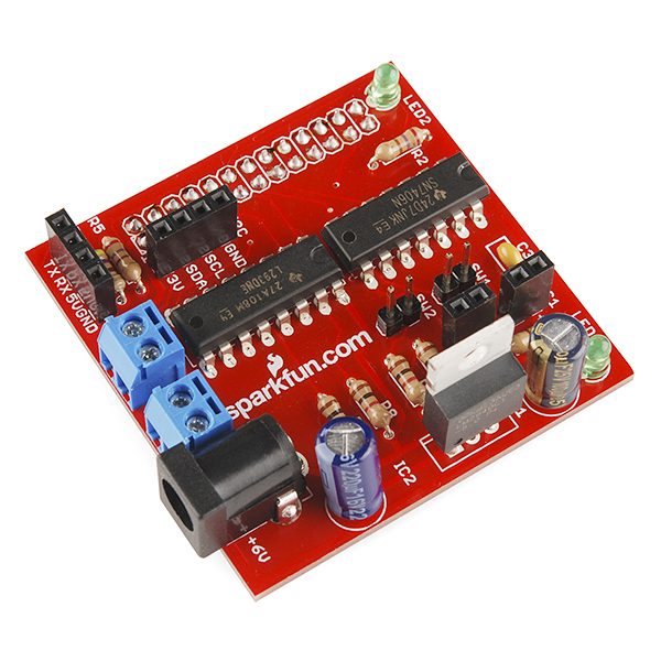
| − | + | [[File:11561-04.jpg]] | |
The Raspberry Pi packs plenty of processing power in a small and inexpensive package and that makes it perfect for robot brains! The only problem? The Raspberry Pi may have plenty of low-level hardware peripherals but motor controllers aren’t one of them. That’s why the RaspiRobot project got started. The RaspiRobot board is an expansion board for the Pi that turns it into a robot controller. | The Raspberry Pi packs plenty of processing power in a small and inexpensive package and that makes it perfect for robot brains! The only problem? The Raspberry Pi may have plenty of low-level hardware peripherals but motor controllers aren’t one of them. That’s why the RaspiRobot project got started. The RaspiRobot board is an expansion board for the Pi that turns it into a robot controller. | ||
| Line 132: | Line 132: | ||
forward_seq = ['1011', '1111', '1110', '1010'] | forward_seq = ['1011', '1111', '1110', '1010'] | ||
The first and third bit of each part of the sequence are always 1, enabling both motors. It is now only the second and fourth bits that control the polarity of each of the two stepper windings. | The first and third bit of each part of the sequence are always 1, enabling both motors. It is now only the second and fourth bits that control the polarity of each of the two stepper windings. | ||
| + | ==Documents== | ||
| + | Schematic [[Media:RaspiRobot_Board.pdf ]] | ||
| + | |||
| + | Eagle Files | ||
| + | |||
| + | Datasheet(L293DNE) [[Media:L293DNE.pdf]] | ||
| + | |||
| + | Datasheet(SN7406N) [[Media:SN7406N.pdf]] | ||
| + | |||
| + | Python Library | ||
| + | |||
| + | Raspirobot Site | ||
Revision as of 03:06, 8 August 2014
Contents
Description
The Raspberry Pi packs plenty of processing power in a small and inexpensive package and that makes it perfect for robot brains! The only problem? The Raspberry Pi may have plenty of low-level hardware peripherals but motor controllers aren’t one of them. That’s why the RaspiRobot project got started. The RaspiRobot board is an expansion board for the Pi that turns it into a robot controller.
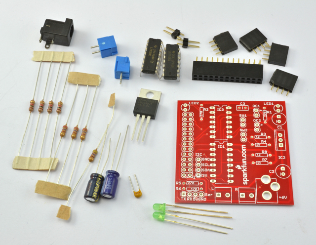
The board comes as a kit of through-hole parts which is easy to assemble with even a basic soldering iron and limited soldering experience. A step-by-step assembly guide is available to help you through the process.
After you’ve assembled it, simply plug the RaspiRobot Board into the GPIO port on the Raspberry Pi and it provides dual bi-directional motor controllers, two open collector outputs, two switch inputs, a pair of status LEDs and even a voltage regulator capable of powering the Pi using a battery source from 7-12VDC.
A Python library module makes it easy to interface with the robot hardware from your software on the Pi. The combination of Raspberry PI and the RaspiRobot Board makes it easier and more affordable than you might think to build a robot with computer vision, web access or even machine learning using the linux operating system and Python code.
Features
- Dual Bi-directional Motor Control
- Voltage Regulator powers Raspberry Pi from Batteries (7-12V)
- 2 x Open collector outputs (25mA)
- 2 x LEDs
- 2 x Switch inputs
- 5V Serial connector
- 3.3V I2C connector
- Simple to use Python library module
Getting start
Once you have built your RaspiRobotBoard, you will need to carry out a few tests, to make sure that everything is working. This tutorial leads you through setting up the software that the RaspiRobotBoard needs and using it with the Raspberry Pi. If you are using a newish distribution of Raspbian or Occidentalis, then they may be already installed. Running the commands again will do no harm.
- Install the libraries
The RaspiRobot library itself requires two other libraries to be installed first, RPi.GPIO and Pyserial. Enter the following commands into a Terminal session on your Raspberry Pi.
>sudo apt-get install python-rpi.gpio
>sudo apt-get install python-serial
The RaspiRobotBoard library itself requires a little bit more effort to install.
On your Raspberry Pi, issue the following commands in a Terminal window:
>wget https://github.com/simonmonk/raspirobotboard/archive/master.zip
>unzip master.zip
>cd raspirobotboard-master
>sudo python setup.py install
Run Some Tests from the Python Console Now that everything is installed, we can experiment with the RaspiRobotBoard.
Open a Python console (Python2 not 3) by typing the following into a Terminal window:
sudo python
Then, within the python console, type the following, one line at a time:
from raspirobotboard import *
rr = RaspiRobot()
rr.set_led1(1)
rr.set_led1(0)
rr.set_led2(1)
rr.set_led2(0)
rr.set_oc1(1)
rr.set_oc1(0)
rr.forward()
rr.left()
rr.right()
rr.stop()
rr.get_range_inch()
rr.sw1_closed()
Build and test a Raspirobt Board
Step one was to check I had the right bits. I opened the packet and laid the components out just like the helpful picture on the website. Mine were different! The official picture shows four 4-way headers, whereas the set I got had two 4-way and two 2-way. A bit further down the page is a list of components, and that did agree with what I had received. Shame about the picture, though.
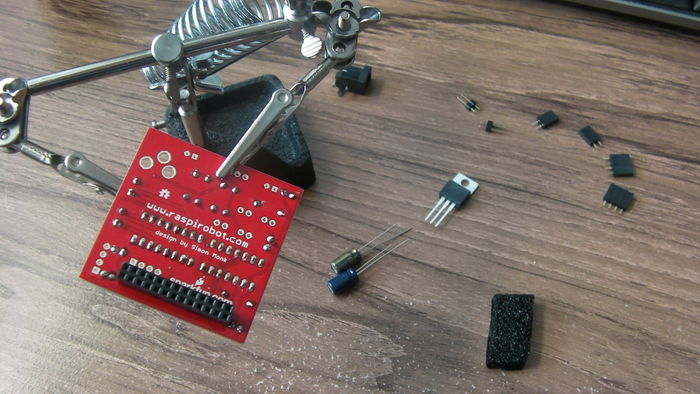
Once I had sorted that out I began assembling the board, with the help of my "third hand". Soldering it was very straigtforward, and all the components fitted nicely into their allotted places.
Once I had installed the various python stuff it requires, I was able to switch the two LEDs on and off. The instructions for switching the motors and open-collector outputs had no effect, of course.
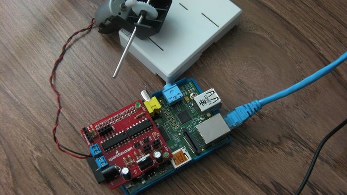
Next, I tried to drive a motor. This is, after all, what the board is supposed to be for - if all I wanted was to switch two LEDs on and off I could have done it much more simply! This, however was where I hit problems. So far I have not been able to get the board to actually drive a motor.
My first attempt was to try using USB power from the Pi. Nothing. But I half expected that - motors can take a lot of power, so the board provides a separate power input to drive the motors and (via a regulator) the Raspberry Pi. The web site says anything from 7-12V will do, so I tried a spare 12V power adaptor which I had lying around and happened to have the right kind of plug. It tested OK with a voltmeter, but did not seem to have enough juice to power up the Pi. Still, it only claimed an output of 400mA, so I tried a bigger one. 500mA was enough to half-start the Raspberry Pi, but not enough to boot the OS. I was sure a 1A adapter would be enough, but this didn't work either. All that happened was the regulator on the RaspiRobot board got very hot.
I know the motor works, because connecting it directly to the power adapter makes it spin happily. The problem definitely seems to be in the power handling on the RaspiRobot board.
Using a RaspiRobot Board to Drive a Bipolar Stepper Motor
- Problem
You want to control a bipolar stepper motor using a RaspiRobot board.
- Solution
The RaspiRobot board uses the power supply directly from its DC socket as the supply to the motor and regulates that same supply down to 5V to drive the Raspberry Pi. So in this case, the 12V power will be supplying both the 12V stepper motor and the Raspberry Pi.
The Raspberry Pi should not be powered through its USB connection when the RaspiRobot board is also powered, or slight differences in the 5V from the Raspberry Pi USB and the 5V regulated supply from the RaspiRobot board could cause large currents to flow and damage either the board or the Raspberry Pi. Power one board or the other, but not both.
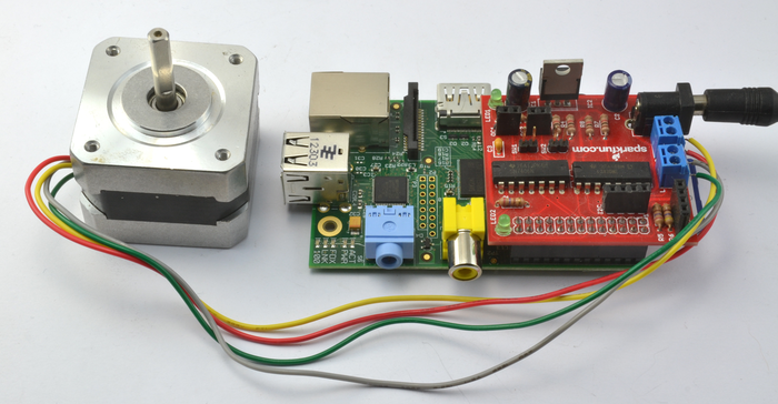
Connect the stepper motor and power supply to the RaspiRobot board as shown in Figure 6-1. The wire colors for the Adafruit 12V stepper motor are in order, from nearest the DC socket: yellow, red, grey, and green.
With a little modification to the pin allocations and step sequence, we can use this program with a RaspiRobot board. Open an editor (nano or IDLE) and paste in the following code. As with all the program examples in this book, you can also download the program from the Code section of the Raspberry Pi Cookbook website, where it is called stepper_rrb.py. This program uses the command line, so you can run it from SSH.
If you’re using Python 3, change the command raw_input to just input:
import RPi.GPIO as GPIO
import time
GPIO.setmode
coil_A_1_pin = 17
coil_A_2_pin = 4
coil_B_1_pin = 10
coil_B_2_pin = 25
GPIO.setup(coil_A_1_pin, GPIO.OUT)
GPIO.setup(coil_A_2_pin, GPIO.OUT)
GPIO.setup(coil_B_1_pin, GPIO.OUT)
GPIO.setup(coil_B_2_pin, GPIO.OUT)
forward_seq = ['1011', '1111', '1110', '1010']
reverse_seq = list(forward_seq) # to copy the list
reverse_seq.reverse()
def forward(delay, steps):
  for i in range(steps):
    for step in forward_seq:
      set_step(step)
      time.sleep(delay)
def backwards(delay, steps):
  for i in range(steps):
    for step in reverse_seq:
      set_step(step)
      time.sleep(delay)
def set_step(step):
  GPIO.output(coil_A_1_pin, step[0] == '1')
  GPIO.output(coil_A_2_pin, step[1] == '1')
  GPIO.output(coil_B_1_pin, step[2] == '1')
  GPIO.output(coil_B_2_pin, step[3] == '1')
while True:
  set_step('0000')
  delay = raw_input("Delay between steps (milliseconds)?")
  steps = raw_input("How many steps forward? ")
  forward(int(delay) / 1000.0, int(steps))
  set_step('0000')
  steps = raw_input("How many steps backwards? ")
  backwards(int(delay) / 1000.0, int(steps))
- Discussion
The RaspiRobot board uses the L293D in a different arrangement from how you used it, as it uses a pin to enable each channel (pins 17 and 10), and a second pair of pins that controls the direction of each motor (pins 4 and 25). This means that as well as changing the pin allocations, you also need to modify the step sequence to:
forward_seq = ['1011', '1111', '1110', '1010']
The first and third bit of each part of the sequence are always 1, enabling both motors. It is now only the second and fourth bits that control the polarity of each of the two stepper windings.
Documents
Schematic Media:RaspiRobot_Board.pdf
Eagle Files
Datasheet(L293DNE) Media:L293DNE.pdf
Datasheet(SN7406N) Media:SN7406N.pdf
Python Library
Raspirobot Site
