Difference between revisions of "Arduino GPRS Shield"
(→Power Up the GPRS Shield) |
(→instructions to test the communication) |
||
| (85 intermediate revisions by the same user not shown) | |||
| Line 1: | Line 1: | ||
== Introduction == | == Introduction == | ||
| − | + | [[File:GPRS1.jpg|400px]] | |
| + | [[File:GPRS2.jpg|400px]] | ||
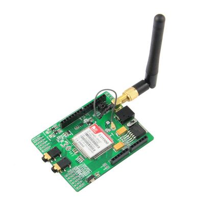
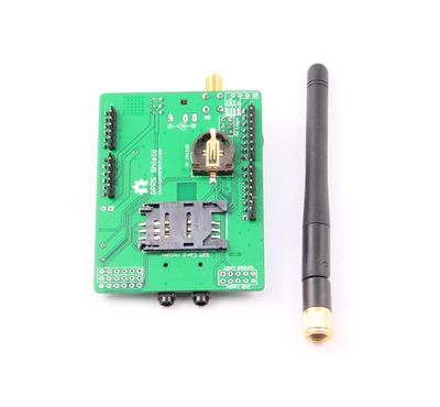
| + | The GPRS Shield is based on SIM900 module from SIMCOM and compatible with Arduino and its clones. The GPRS Shield provides you a way to communicate using the GSM cell phone network. The shield allows you to achieve SMS, MMS, GPRS and Audio via UART by sending AT commands (GSM 07.07 ,07.05 and SIMCOM enhanced AT Commands). The shield also has the 12 GPIOs, 2 PWMs and an ADC of the SIM900 module(They are all 2V8 logic) present onboard. | ||
== Features == | == Features == | ||
| Line 33: | Line 35: | ||
*The product is provided as is without an insulating enclosure. Please observe ESD precautions specially in dry (low humidity) weather. | *The product is provided as is without an insulating enclosure. Please observe ESD precautions specially in dry (low humidity) weather. | ||
*The factory default setting for the GPRS Shield UART is 19200 bps 8-N-1. (Can be changed using AT commands). | *The factory default setting for the GPRS Shield UART is 19200 bps 8-N-1. (Can be changed using AT commands). | ||
| − | |||
| − | |||
| − | |||
| − | + | == Hardware Diagram == | |
| + | [[File:GPRS001.jpg|700px]] | ||
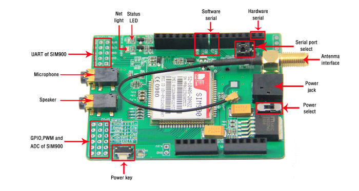
| − | + | *Power select - select the power supply for GPRS shield(external power or 5v of arduino) | |
| + | *Power jack - connected to external 4.8~5VDC power supply | ||
| + | *Antenna interface - connected to external antenna | ||
| + | *Serial port select - select either software serial port or hareware serial port to be connected to GPRS Shield | ||
| + | *Hardware Serial - D0/D1 of Arduino | ||
| + | *Software serial - D7/D8 of Arduino | ||
| + | *Status LED - tell whether the power of SIM900 is on | ||
| + | *Net light - tell the status about SIM900 linking to the net | ||
| + | *UART of SIM900 - UART pins breakout of SIM900 | ||
| + | *Microphone - to answer the phone call | ||
| + | *Speaker - to answer the phone call | ||
| + | *GPIO,PWM and ADC of SIM900 - GPIO,PWM and ADC pins breakout of SIM900 | ||
| + | *Power key - power up and down for SIM900 | ||
| − | * | + | *Pins usage on Arduino |
| + | *D0 - Unused if you select software serial port to communicate with GPRS Shield | ||
| + | *D1 - Unused if you select software serial port to communicate with GPRS Shield | ||
| + | *D2 - Unused | ||
| + | *D3 - Unused | ||
| + | *D4 - Unused | ||
| + | *D5 - Unused | ||
| + | *D6 - Unused | ||
| + | *D7 - Used if you select software serial port to communicate with GPRS Shield | ||
| + | *D8 - Used if you select software serial port to communicate with GPRS Shield | ||
| + | *D9 - Used for software control the power up or down of the SIM900 | ||
| + | *D10 - Unused | ||
| + | *D11 - Unused | ||
| + | *D12 - Unused | ||
| + | *D13 - Unused | ||
| + | *D14(A0) - Unused | ||
| + | *D15(A1) - Unused | ||
| + | *D16(A2) - Unused | ||
| + | *D17(A3) - Unused | ||
| + | *D18(A4) - Unused | ||
| + | *D19(A5) - Unused | ||
| + | *Note: A4 and A5 are connected to the I2C pins on the SIM900. The SIM900 however cannot be accessed via the I2C . | ||
| − | == | + | == Getting Started == |
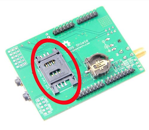
| + | *'''Insert a unlock SIM card''' | ||
| + | [[File:GPRS005.jpg|500px]] | ||
| + | |||
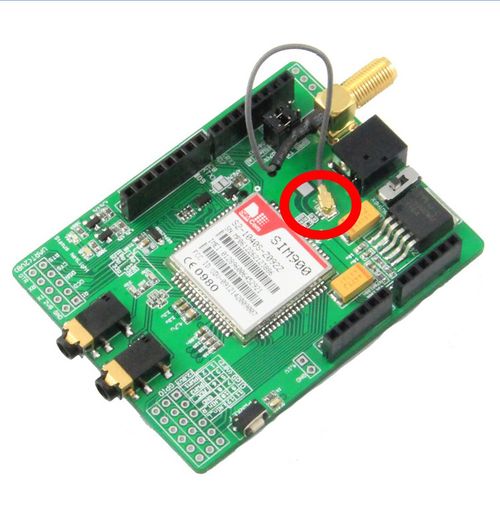
| + | *'''Make sure the antenna pad buckled properly''' | ||
| + | [[File:GPRS002.jpg|500px]] | ||
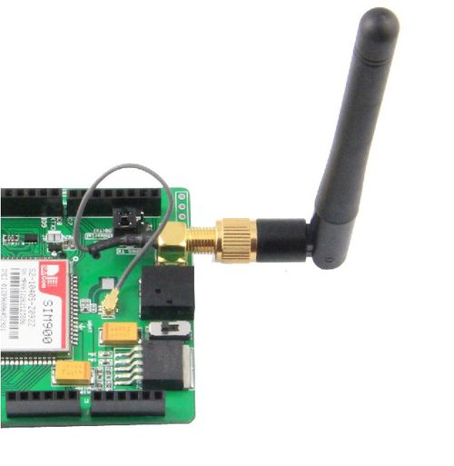
| + | *'''Assemble the GSM antenna''' | ||
| + | [[File:GPRS003.jpg|500px]] | ||
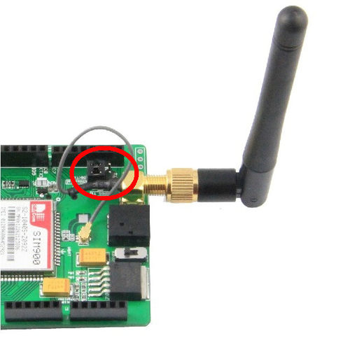
| − | + | *'''Chooose communication port properly using the jumpers''' | |
| + | [[File:GPRS0003.jpg|500px]] | ||
| − | + | *'''Assemble GPRS shield to Arduino and download the sketch''' | |
| − | + | *'''Press power key about 2 seconds to turn on the GPRS shield''' | |
| − | + | === Indicator LEDs === | |
| + | There are three indicator LEDs(PWR(Green), Staus(Blue), Netlight(Red)) on the GPRS Shield, users can know about the working state of the shield based on the three indicator LEDs. Detailed information please refer to the following table: | ||
| − | + | [[File:Indicator LEDs.jpg]] | |
| − | === Power Up and Power | + | === Power Up and Power Down the GPRS Shield === |
==== Power Up the GPRS Shield ==== | ==== Power Up the GPRS Shield ==== | ||
| Line 62: | Line 104: | ||
The GPRS Shield can be turned on by two ways: | The GPRS Shield can be turned on by two ways: | ||
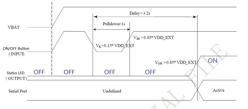
| − | *1, Hardware Triger; Press the ON/OFF Button about two seconds.The power up scenarios illustrates as following figure: | + | *1, '''Hardware Triger'''; Press the ON/OFF Button about two seconds.The power up scenarios illustrates as following figure: |
[[File:GPRS ONs.jpg|800px]] | [[File:GPRS ONs.jpg|800px]] | ||
| − | + | [[File:JP.png]] | |
| − | *2, Software Triger; If use this way to power up the GPRS Shield, JP need to be soldered, then Digital Pin 9 of the Arduino will act as Software Triger port and Digital Pin 9 can not be use as other purpose. Then give Digital Pin 9 a Turn on Impulse can power up the GPRS Shield. The power up scenarios illustrates as following figure: | + | *2, '''Software Triger'''; If use this way to power up the GPRS Shield, JP need to be soldered, then Digital Pin 9 of the Arduino will act as Software Triger port and Digital Pin 9 can not be use as other purpose. Then give Digital Pin 9 a Turn on Impulse can power up the GPRS Shield. The power up scenarios illustrates as following figure: |
[[File:GPRS Pwrs.jpg|800px]] | [[File:GPRS Pwrs.jpg|800px]] | ||
| Line 85: | Line 127: | ||
The GPRS Shield can be turned off by following ways: | The GPRS Shield can be turned off by following ways: | ||
| − | *1, Normal power down procedure: Turn off the GPRS shield by using Hardware Triger; Press the ON/OFF Button about two seconds. | + | *1, '''Normal power down procedure''': Turn off the GPRS shield by using Hardware Triger; Press the ON/OFF Button about two seconds. |
The power down scenarios illustrates as following figure: | The power down scenarios illustrates as following figure: | ||
| + | |||
[[File:Gprspowerdown.jpg|800px]] | [[File:Gprspowerdown.jpg|800px]] | ||
| − | 2, Normal power down procedure: If JP is soldered, then give Digital Pin 9 of the Arduino(act as Software Triger) a Turn off Impulse can turn off the GPRS Shield. The power down scenarios illustrates as following figure: | + | 2, '''Normal power down procedure''': If JP is soldered, then give Digital Pin 9 of the Arduino(act as Software Triger) a Turn off Impulse can turn off the GPRS Shield. The power down scenarios illustrates as following figure: |
| + | |||
[[File:GprsPwrd1.jpg|800px]] | [[File:GprsPwrd1.jpg|800px]] | ||
| Line 105: | Line 149: | ||
} | } | ||
| − | *3, Normal power down procedure:Turn off the GPRS shield by sending AT command “AT+CPOWD=1” to SIM900 module. | + | *3, '''Normal power down procedure''':Turn off the GPRS shield by sending AT command “AT+CPOWD=1” to SIM900 module. |
When GPRS Shield power dowm in Normal power down procedure, the procedure lets the SIM900 log off from the network and allows the software to enter into a secure state and save data before completely disconnecting the power supply. Before the completion of the power down procedure the SIM900 will send out result code: NORMAL POWER DOWN | When GPRS Shield power dowm in Normal power down procedure, the procedure lets the SIM900 log off from the network and allows the software to enter into a secure state and save data before completely disconnecting the power supply. Before the completion of the power down procedure the SIM900 will send out result code: NORMAL POWER DOWN | ||
| − | *4, Over-voltage or Under-voltage Automatic Power Down: SIM900 will constantly monitor the voltage applied on the VBAT. | + | *4, '''Over-voltage or Under-voltage Automatic Power Down''': SIM900 will constantly monitor the voltage applied on the VBAT. |
①If the voltage ≤ 3.3V, the following URC will be presented: | ①If the voltage ≤ 3.3V, the following URC will be presented: | ||
| Line 127: | Line 171: | ||
OVER-VOLTAGE POWER DOWN | OVER-VOLTAGE POWER DOWN | ||
| − | *5, Over-temperature or Under-temperature Automatic Power Down: SIM900 will constantly monitor the temperature of the module. | + | *5, '''Over-temperature or Under-temperature Automatic Power Down''': SIM900 will constantly monitor the temperature of the module. |
①If the temperature > 80℃, the following URC will be presented: | ①If the temperature > 80℃, the following URC will be presented: | ||
| Line 146: | Line 190: | ||
When the GPRS Shield encounters POWER DOWN scenario, the AT commands can not be executed. The SIM900 logs off from network and enters the POWER DOWN mode, only the RTC is still active. POWER DOWN can also be indicated by STATUS LED(Blue), which is off in this mode. | When the GPRS Shield encounters POWER DOWN scenario, the AT commands can not be executed. The SIM900 logs off from network and enters the POWER DOWN mode, only the RTC is still active. POWER DOWN can also be indicated by STATUS LED(Blue), which is off in this mode. | ||
| − | Note: | + | '''Note''': |
| − | *To monitor the temperature, users can use the “AT+CMTE” command to read the temperature when GPRS Shield is powered on. | + | *'''To monitor the temperature, users can use the “AT+CMTE” command to read the temperature when GPRS Shield is powered on. ''' |
| − | *To monitor the supply voltage, users can use the “AT+CBC” command which includes a parameter: voltage value(in mV) when GPRS Shield is powered on. | + | *'''To monitor the supply voltage, users can use the “AT+CBC” command which includes a parameter: voltage value(in mV) when GPRS Shield is powered on.''' |
| − | |||
| − | |||
=== Serial Port(UART) Communication === | === Serial Port(UART) Communication === | ||
| Line 158: | Line 200: | ||
[[File:GPRSComs.jpg|700px]] | [[File:GPRSComs.jpg|700px]] | ||
| − | Note: | + | '''Note: ''' |
| − | * | + | <font color="red"> |
| − | + | *Not all Arduino boards support software serial on D7 and D8, For example Arduino Mega and Mega 2560 only support the following pins for RX: 10, 11, 12, 13, 50, 51, 52, 53, 62, 63, 64, 65, 66, 67, 68, 69. So Arduino Mega doesn't support soft serial on Pin D7 and D8. If using GPRS shield with Ardiuno Mega, please use the hardware serial or use the jumper wires wiring GPRS TX and RX to the pins support interrupt on Ardiuno Mega. And not all pins on the Leonardo support change interrupts, so only the following can be used for RX: 8, 9, 10, 11, 14 (MISO), 15 (SCK), 16 (MOSI). More information about Softserial library please visit [http://arduino.cc/en/Reference/SoftwareSerial http://arduino.cc/en/Reference/SoftwareSerial] | |
| − | |||
| − | |||
| − | + | </font> | |
| − | |||
| − | + | *Users can use “AT+IPR=?” command to see supported baudrate, it will response a list of supported baudrate. | |
| + | *Users can use “AT+IPR=x”(x is value of supported baudrate) to set a fixed baud rate and save the configuration to non-volatile flash memory. | ||
| − | === | + | === Upload Sketch to Arduino === |
| − | + | [[File:Grpsaurduinouart.jpg|600px]] | |
| − | + | The following sketch configures Arduino/Arduino clone as serial link between PC and the GPRS Shield(Jumpers on SWserial side). PC would need a serial terminal software to communicate with it - Window's built-in HyperTerminal, Arduino IDE's Serial Monitor, [http://musicshield.googlecode.com/files/sscom32E.exe Serial Terminals(sscom32)] or [http://sites.google.com/site/terminalbpp/ Bray++ Terminal]. | |
| − | + | The GPRS Shield comes with all the accessories that you need to get started with sending data over the GSM network except an Arduino board and a GSM SIM Card. If you want to make voice calls, you would also require a headset with microphone. | |
| − | The | ||
| − | === | + | ====Step 1: Creating a test setup for the GPRS Shield==== |
| − | + | AT Commands are simple textual commands sent to the GPRS modem over its serial interface (UART), so you can use any serial terminal software to communicate with it.<br> | |
| − | + | Note: Almost all the AT commands should be sent followed by '''carriage return''' and you need to select the "+CR"option in the serial port terminal.To experiment with AT commands, you would require a way to power up and communicate with your GPRS Shield. The best way to do this using an Arduino Duemilanove board.<br> | |
| − | |||
| − | + | #Follow the previously described hardware installation steps to set up the hardware system; | |
| + | #Make sure the GPRS_TX & GPRS_RX jumpers on the GPRS Shield are mounted in SWSerial position - that is we want GPRS_TX to be connected to D7(RX) and GPRS_RX to D8(TX). | ||
| + | #Connect the Arduino Duemilanove to your computer using a USB cable. | ||
| + | #The ATmega328P microcontroller on Duemilanove board has only one UART which is used for communicating with the PC. What we need is an Arduino Sketch running inside the ATmega328P that would emulate a second serial port (UART) using software on the digital pins D8 and D7 and patch through all the communication between this second software serial port and the actual hardware serial port. By doing this, all the data coming from the computer (connected to the actual hardware UART) would be routed to the GPRS Shield (connected to software UART) then, we would be able to issue AT commands to control the GPRS Shield. The block diagram outlining this scheme is shown below. | ||
| − | + | For developing such a program, we require to use the SoftwareSerial library included in the libraries of Arduino 1.0 already and the demo code below. | |
//Serial Relay - Arduino will patch a | //Serial Relay - Arduino will patch a | ||
| Line 193: | Line 234: | ||
//Computer is connected to Hardware UART | //Computer is connected to Hardware UART | ||
//GPRS Shield is connected to the Software UART | //GPRS Shield is connected to the Software UART | ||
| − | + | #include <SoftwareSerial.h> | |
| − | #include < | + | SoftwareSerial GPRS(7, 8); |
| − | + | unsigned char buffer[64]; // buffer array for data recieve over serial port | |
| − | + | int count=0; // counter for buffer array | |
| − | |||
void setup() | void setup() | ||
{ | { | ||
| − | + | GPRS.begin(19200); // the GPRS baud rate | |
| − | Serial.begin(19200); | + | Serial.begin(19200); // the Serial port of Arduino baud rate. |
} | } | ||
| − | |||
void loop() | void loop() | ||
{ | { | ||
| − | + | if (GPRS.available()) // if date is comming from softwareserial port ==> data is comming from gprs shield | |
| + | { | ||
| + | while(GPRS.available()) // reading data into char array | ||
{ | { | ||
| − | + | buffer[count++]=GPRS.read(); // writing data into array | |
| − | + | if(count == 64)break; | |
| − | + | } | |
| − | + | Serial.write(buffer,count); // if no data transmission ends, write buffer to hardware serial port | |
| − | + | clearBufferArray(); // call clearBufferArray function to clear the storaged data from the array | |
| − | + | count = 0; // set counter of while loop to zero | |
| − | + | } | |
| + | if (Serial.available()) // if data is available on hardwareserial port ==> data is comming from PC or notebook | ||
| + | GPRS.write(Serial.read()); // write it to the GPRS shield | ||
| + | } | ||
| + | void clearBufferArray() // function to clear buffer array | ||
| + | { | ||
| + | for (int i=0; i<count;i++) | ||
| + | { buffer[i]=NULL;} // clear all index of array with command NULL | ||
} | } | ||
| − | + | #.Upload the sketch to the Arduino board. | |
| + | #.Download and fire up serial tool if you don't have one. Choose the correct COM port for Arduino, and set it to operate at 19200 8-N-1 and then click "Open Com". | ||
| + | #.You can power on or off the the SIM900 by pressing the button about 2 second. After power on, the red LED will be on, and the green one beside it will blink and the shield has found the net if it blinks every 3 seconds. | ||
| + | |||
| + | Also, in the serial monitor you should see messages from the shield such as | ||
| + | RDY | ||
| + | |||
| + | +CFUN: 1 | ||
| − | + | +CPIN: READY | |
| − | |||
| − | + | Call Ready | |
| − | |||
| − | + | If you can not see the messages in the serial monitor, you should click the "send new" option that will add carriage return at the end of AT command and then send AT command "AT+IPR=19200" to set the baud rate of the SIM900. | |
| − | === | + | [[File:Gprs 1.jpg|400px]] |
| − | + | ||
| − | + | *Step 2: Sending a text message (SMS) | |
| − | + | Now that our test setup is ready, let's play around with some AT Commands manually before moving on to programming the Arduino to do this. Let's try sending an SMS to start. | |
| + | |||
| + | #.Create the setup as described in Step 1 above. | ||
| + | #.Through your serial terminal software, send AT+CMGF=1 and press the Enter key. The GPRS Shield can send SMSes in two modes: Text mode and PDU (or binary) mode. Since we want to send out a human readable message, we will select the text mode. The GPRS Shield will respond with an OK. | ||
| + | #.Click "send new" option and send AT+CMGS="+918446043032". This will instruct the GPRS Shield to start accepting text for a new message meant for the phone number specified (replace the number with the phone number of the target phone). The GPRS Shield will send a > to remind you typing the message. | ||
| + | |||
| + | [[File:Gprs 2.jpg|400px]] | ||
| + | |||
| + | #.Start typing your message and when you are done, and click "send hex" option and then send a hex: 1A. The modem will accept the message and respond with an OK. A few moments later, the message should be received on the handset whose number you had specified.You can refer to the picture below. | ||
| + | |||
| + | [[File:Gprs 3.jpg|400px]] | ||
| + | |||
| + | NOTE: If, in spite of following the steps as specified above, you aren't able to receive the message on the target handset, then it might be that you need to set the SMS Message Center number. Send the command AT+CSCA="+919032055002" and press the Enter Key. Send this command in between the AT+CMGF and AT+CMGS commands. Replace the phone number specified in the command above with the SMS Center number of your GSM Service Provider. The message center number is specific to each service provider (for example +919032055002 is the message center number for Tata DoCoMo, Pune, India). You can get the message center number by calling up the customer care center of the GSM Service Provider and asking them for it. | ||
| + | |||
| + | ====SoftwareSerial library Notes==== | ||
| + | |||
| + | With Arduino 1.0 you should be able to use the SoftwareSerial library included with the distribution (instead of NewSoftSerial). However, you must be aware that the buffer reserved for incoming messages are hardcoded to 64 bytes in the library header, "SoftwareSerial.h": | ||
| + | 1.define _SS_MAX_RX_BUFF 64 // RX buffer size | ||
| + | |||
| + | This means that if the GPRS module responds with more data than that, you are likely to loose it with a buffer overflow! For instance, reading out an SMS from the module with "AT+CMGR=xx" (xx is the message index), you might not even see the message part because the preceding header information (like telephone number and time) takes up a lot of space. The fix seems to be to manually change _SS_MAX_RX_BUFF to a higher value (but reasonable so you don't use all you precious memory!) | ||
| + | |||
| + | The Softwareserial library has the following limitations (taken from arduino page) If using multiple software serial ports, only one can receive data at a time. http://arduino.cc/hu/Reference/SoftwareSerial This means that if you try to add another serial device ie grove serial LCD you may get communication errors unless you craft your code carefully. | ||
| + | |||
| + | ===A Simple Source Code Examples=== | ||
| + | The demo code below is for the Xduino to send SMS message/dial a voice call/submit a http request to a website and upload datas to the pachube. It has been tested on Arduino Duemilanove but will work on any compatible variant, plesse note that this sketch uses the sorfware UART of ATmega328P. please follow the following steps for running this sketch. | ||
| + | |||
| + | #.With the GPRS Shield removed, download this sketch into your Arduino. | ||
| + | #.Disconnect the Xduino from USB port to remove power source. | ||
| + | #.Set the Serial Port jumpers on the GPRS Shield in SWserial position, to use the Soft Serial port of Arduino. | ||
| + | #.Connect the antenna to the GPRS Shield and insert the SIM Card. | ||
| + | #.Mount the GPRS Shield on Arduino. | ||
| + | #.Connect the Arduino to the computer by USB, and fire up your favorite serial terminal software on computer, choose the COM port for Arduino, set it to operate at 19200 8-N-1. | ||
| + | #.Type command in the terminal to execute different function, threr are 4 functions in the demo: | ||
| + | ##.If you input 't', the demo will send a SMS message to another cellphone which you set(you need set the number in the code); | ||
| + | ##.If you input 'd', the program will dial a call to the other cellphone that you set(it is also need you set in the code ); | ||
| + | ##.If you input 'h', it will submit a http request to a web that you want to access(it need you set the web adress in the code), it will return a string from the website if it goes correctly; | ||
| + | ##.If you input 's', it will upload the datas to the pachube(for detail you can refer to the explanation in the code). I strongly recommend you input 'h' before input 's', because uploading datas to the pachube need do some setting, after execute the function of submit a http request, the setting will be set. | ||
| + | #.If the program returns error in the terminal after you typed the command, don't worry, just try input the command again. | ||
| + | |||
| + | |||
| + | /*Note: this code is a demo for how to using gprs shield to send sms message, dial a voice call and | ||
| + | send a http request to the website, upload data to pachube.com by TCP connection, | ||
| + | The microcontrollers Digital Pin 7 and hence allow unhindered | ||
| + | communication with GPRS Shield using SoftSerial Library. | ||
| + | IDE: Arduino 1.0 or later | ||
| + | Replace the following items in the code: | ||
| + | 1.Phone number, don't forget add the country code | ||
| + | 2.Replace the Access Point Name | ||
| + | 3. Replace the Pachube API Key with your personal ones assigned | ||
| + | to your account at cosm.com | ||
| + | */ | ||
| + | #include <SoftwareSerial.h> | ||
| + | #include <String.h> | ||
| + | SoftwareSerial mySerial(7, 8); | ||
void setup() | void setup() | ||
{ | { | ||
| − | mySerial.begin(19200); | + | mySerial.begin(19200); // the GPRS baud rate |
| − | + | Serial.begin(19200); // the GPRS baud rate | |
| − | + | delay(500); | |
| − | |||
| − | |||
| − | |||
| − | |||
| − | |||
| − | |||
| − | |||
| − | |||
| − | |||
| − | |||
| − | |||
| − | |||
| − | |||
| − | |||
| − | |||
| − | |||
| − | |||
} | } | ||
| − | |||
void loop() | void loop() | ||
{ | { | ||
| − | + | //after start up the program, you can using terminal to connect the serial of gprs shield, | |
| − | + | //if you input 't' in the terminal, the program will execute SendTextMessage(), it will show how to send a sms message, | |
| + | //if input 'd' in the terminal, it will execute DialVoiceCall(), etc. | ||
| + | if (Serial.available()) | ||
| + | switch(Serial.read()) | ||
| + | { | ||
| + | case 't': | ||
| + | SendTextMessage(); | ||
| + | break; | ||
| + | case 'r': | ||
| + | RecieveTextMessage();//This program code by directive'r'to receive, by receiving the information after the return to call the function | ||
| + | //to verify receiving function. But it can not display the received content in SIM. | ||
| + | DialVoiceCall(); | ||
| + | break; | ||
| + | case 'd': | ||
| + | DialVoiceCall(); | ||
| + | break; | ||
| + | case 'h': | ||
| + | SubmitHttpRequest(); | ||
| + | break; | ||
| + | case 's': | ||
| + | Send2Pachube(); | ||
| + | break; | ||
| + | } | ||
| + | if (mySerial.available()) | ||
| + | Serial.write(mySerial.read()); | ||
} | } | ||
| − | + | ///SendTextMessage() | |
| − | == | + | ///this function is to send a sms message |
| − | + | void SendTextMessage() | |
| − | + | { | |
| − | + | mySerial.print("AT+CMGF=1\r"); //Because we want to send the SMS in text mode | |
| − | + | delay(100); | |
| − | void | + | mySerial.println("AT + CMGS = \"+86138xxxxx615\"");//send sms message, be careful need to add a country code before the cellphone number |
| + | delay(100); | ||
| + | mySerial.println("A test message!");//the content of the message | ||
| + | delay(100); | ||
| + | mySerial.println((char)26);//the ASCII code of the ctrl+z is 26 | ||
| + | delay(100); | ||
| + | mySerial.println(); | ||
| + | } | ||
| + | void RecieveTextMessage() | ||
| + | { | ||
| + | //mySerial.print("AT+CMGF=1\r"); //Because we want to recieve the SMS in text mode | ||
| + | //delay(100); | ||
| + | mySerial.print("AT+CMGR=1\r");//Because we want to recieve the SMS in text mode | ||
| + | delay(100); | ||
| + | mySerial.println("AT + CSCA = \"+86135*********\"");//recieve sms message, be careful need to add a country code before the cellphone number | ||
| + | delay(100); | ||
| + | mySerial.println("A test message!");//the content of the message | ||
| + | delay(100); | ||
| + | mySerial.println((char)26);//the ASCII code of the ctrl+z is 26 | ||
| + | delay(100); | ||
| + | mySerial.println(); | ||
| + | //return r; | ||
| + | } | ||
| + | ///DialVoiceCall | ||
| + | ///this function is to dial a voice call | ||
| + | void DialVoiceCall() | ||
{ | { | ||
| − | + | mySerial.println("ATD + +86138xxxxx615;");//dial the number | |
| − | + | delay(100); | |
| − | + | mySerial.println(); | |
| − | mySerial.println(" | ||
| − | |||
| − | |||
| − | |||
| − | |||
| − | |||
| − | |||
| − | delay( | ||
| − | |||
| − | |||
| − | mySerial.println( | ||
| − | |||
| − | |||
| − | |||
| − | |||
} | } | ||
| − | + | ///SubmitHttpRequest() | |
| − | void | + | ///this function is submit a http request |
| + | ///attention:the time of delay is very important, it must be set enough | ||
| + | void SubmitHttpRequest() | ||
{ | { | ||
| − | // | + | mySerial.println("AT+CSQ"); |
| + | delay(100); | ||
| + | ShowSerialData();// this code is to show the data from gprs shield, in order to easily see the process of how the gprs shield submit a http request, and the following is for this purpose too. | ||
| + | mySerial.println("AT+CGATT?"); | ||
| + | delay(100); | ||
| + | ShowSerialData(); | ||
| + | mySerial.println("AT+SAPBR=3,1,\"CONTYPE\",\"GPRS\"");//setting the SAPBR, the connection type is using gprs | ||
| + | delay(1000); | ||
| + | ShowSerialData(); | ||
| + | mySerial.println("AT+SAPBR=3,1,\"APN\",\"CMNET\"");//setting the APN, the second need you fill in your local apn server | ||
| + | delay(4000); | ||
| + | ShowSerialData(); | ||
| + | mySerial.println("AT+SAPBR=1,1");//setting the SAPBR, for detail you can refer to the AT command mamual | ||
| + | delay(2000); | ||
| + | ShowSerialData(); | ||
| + | mySerial.println("AT+HTTPINIT"); //init the HTTP request | ||
| + | delay(2000); | ||
| + | ShowSerialData(); | ||
| + | mySerial.println("AT+HTTPPARA=\"URL\",\"www.google.com.hk\"");// setting the httppara, the second parameter is the website you want to access | ||
| + | delay(1000); | ||
| + | ShowSerialData(); | ||
| + | mySerial.println("AT+HTTPACTION=0");//submit the request | ||
| + | delay(10000);//the delay is very important, the delay time is base on the return from the website, if the return datas are very large, the time required longer. | ||
| + | //while(!mySerial.available()); | ||
| + | ShowSerialData(); | ||
| + | mySerial.println("AT+HTTPREAD");// read the data from the website you access | ||
| + | delay(300); | ||
| + | ShowSerialData(); | ||
| + | mySerial.println(""); | ||
| + | delay(100); | ||
} | } | ||
| − | + | ///send2Pachube()/// | |
| − | + | ///this function is to send the sensor data to the pachube, you can see the new value in the pachube after execute this function/// | |
| − | + | void Send2Pachube() | |
| − | |||
| − | |||
| − | |||
| − | |||
| − | |||
| − | void | ||
{ | { | ||
| − | mySerial. | + | mySerial.println("AT+CGATT?"); |
| − | + | delay(100); | |
| + | ShowSerialData(); | ||
| + | mySerial.println("AT+CSTT=\"CMNET\"");//start task and setting the APN, | ||
| + | delay(1000); | ||
| + | ShowSerialData(); | ||
| + | mySerial.println("AT+CIICR");//bring up wireless connection | ||
| + | delay(300); | ||
| + | ShowSerialData(); | ||
| + | mySerial.println("AT+CIFSR");//get local IP adress | ||
| + | delay(2000); | ||
| + | ShowSerialData(); | ||
| + | mySerial.println("AT+CIPSPRT=0"); | ||
| + | delay(3000); | ||
| + | ShowSerialData(); | ||
| + | mySerial.println("AT+CIPSTART=\"tcp\",\"api.cosm.com\",\"8081\"");//start up the connection | ||
delay(2000); | delay(2000); | ||
| + | ShowSerialData(); | ||
| + | mySerial.println("AT+CIPSEND");//begin send data to remote server | ||
| + | delay(4000); | ||
| + | ShowSerialData(); | ||
| + | String humidity = "1031";//these 4 line code are imitate the real sensor data, because the demo did't add other sensor, so using 4 string variable to replace. | ||
| + | String moisture = "1242";//you can replace these four variable to the real sensor data in your project | ||
| + | String temperature = "30";// | ||
| + | String barometer = "60.56";// | ||
| + | mySerial.print("{\"method\": \"put\",\"resource\": \"/feeds/42742/\",\"params\"");//here is the feed you apply from pachube | ||
| + | delay(500); | ||
| + | ShowSerialData(); | ||
| + | mySerial.print(": {},\"headers\": {\"X-PachubeApiKey\":");//in here, you should replace your pachubeapikey | ||
| + | delay(500); | ||
| + | ShowSerialData(); | ||
| + | mySerial.print(" \"_cXwr5LE8qW4a296O-cDwOUvfddFer5pGmaRigPsiO0");//pachubeapikey | ||
| + | delay(500); | ||
| + | ShowSerialData(); | ||
| + | mySerial.print("jEB9OjK-W6vej56j9ItaSlIac-hgbQjxExuveD95yc8BttXc");//pachubeapikey | ||
| + | delay(500); | ||
| + | ShowSerialData(); | ||
| + | mySerial.print("Z7_seZqLVjeCOmNbEXUva45t6FL8AxOcuNSsQS\"},\"body\":"); | ||
| + | delay(500); | ||
| + | ShowSerialData(); | ||
| + | mySerial.print(" {\"version\": \"1.0.0\",\"datastreams\": "); | ||
| + | delay(500); | ||
| + | ShowSerialData(); | ||
| + | mySerial.println("[{\"id\": \"01\",\"current_value\": \"" + barometer + "\"},"); | ||
| + | delay(500); | ||
| + | ShowSerialData(); | ||
| + | mySerial.println("{\"id\": \"02\",\"current_value\": \"" + humidity + "\"},"); | ||
| + | delay(500); | ||
| + | ShowSerialData(); | ||
| + | mySerial.println("{\"id\": \"03\",\"current_value\": \"" + moisture + "\"},"); | ||
| + | delay(500); | ||
| + | ShowSerialData(); | ||
| + | mySerial.println("{\"id\": \"04\",\"current_value\": \"" + temperature + "\"}]},\"token\": \"lee\"}"); | ||
| + | delay(500); | ||
| + | ShowSerialData(); | ||
| + | mySerial.println((char)26);//sending | ||
| + | delay(5000);//waitting for reply, important! the time is base on the condition of internet | ||
| + | mySerial.println(); | ||
| + | ShowSerialData(); | ||
| + | mySerial.println("AT+CIPCLOSE");//close the connection | ||
| + | delay(100); | ||
| + | ShowSerialData(); | ||
} | } | ||
| − | + | void ShowSerialData() | |
| − | void | ||
{ | { | ||
| − | + | while(mySerial.available()!=0) | |
| − | + | Serial.write(mySerial.read()); | |
| − | |||
| − | |||
| − | |||
| − | |||
| − | |||
| − | |||
| − | |||
| − | |||
} | } | ||
== Schematics == | == Schematics == | ||
| − | GPRSshield_sch.pdf | + | [http://www.geeetech.com/Documents/GPRSshield_sch.pdf File:GPRSshield_sch.pdf] |
== Resources == | == Resources == | ||
| − | SIM900 AT Commands Manual v1.03.pdf | + | [http://www.geeetech.com/Documents/SIM900_AT_Command_Manual_V1.03.pdf SIM900 AT Commands Manual v1.03.pdf] |
SIM900_hd_v1.06.pdf | SIM900_hd_v1.06.pdf | ||
| Line 332: | Line 529: | ||
SIM900_TCP/IP Application Note | SIM900_TCP/IP Application Note | ||
| − | Si5902BDC - Dual N-Channel 30 V (D-S) MOSFETs (used for 2.8V <> 5.0V translation for Serial Interface) | + | Si5902BDC - Dual N-Channel 30 V (D-S) MOSFETs (used for 2.8V <> 5.0V translation for Serial Interface) |
| + | |||
| + | |||
| + | == instructions to test the communication == | ||
| + | |||
| + | If you are using a Router rather than a modem or Exchanger, before networking testing for the GPRS module, you should pay attention to the following tips. | ||
| + | |||
| + | 1. Specify a fixed IP address for Local Host,hereinafter referred to as "Local Host IP". | ||
| + | |||
| + | 2. Set a Port Mapping on the Router and map the port to Local Host IP. We call the set port "Local Host Port". Local Host Port is within 0 and 65535. | ||
| + | |||
| + | 3. Open home page (Google), input "IP" to check your Public IP. | ||
| + | |||
| + | [[File:Gprs_(2).jpg|500px|]] | ||
| + | |||
| + | === FAQS === | ||
| + | Q1. Why should I specify a "Local Host Port" on the Router (Port Mapping)? | ||
| + | |||
| + | ADSL dials through a router and the host shares network through the router. In this case, the host usually extracts Private IP such as 192.168.x.x. for such reasons, only when you specify a ‘Local Host Port’ on the Router (Port Mapping) and forward it to the corresponding Local Host, can the Internet access to the Local Host through this Port. | ||
| + | |||
| + | |||
| + | Q2. Why should I specify a Fixed Private IP for the Local Host? | ||
| + | |||
| + | Port Mapping is a one-to-one process. If the Local Host is specified to obtain IP automatically, the IP address will probably change when the computer restarts or reconnects to the network. Therefore, it is necessary to specify a Fixed Private IP. | ||
| + | |||
| + | === Tools === | ||
| + | 1. Arduino IDE | ||
| + | |||
| + | 2. Net Assist | ||
| + | |||
| + | 3. STC-SIP | ||
| + | |||
| + | === Steps === | ||
| + | 1, Start the "Net Assist", choose "TCP server" in the dropdown menus of "protocol" (UDP Server is not recommended), change the "Local Host IP" into the Fixed IP. Input the "Local host port" set before and then click “Connect “. As shown in following the picture. | ||
| + | |||
| + | [[File:Gpr5s.jpg|500px|]] | ||
| + | |||
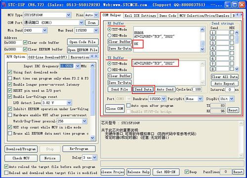
| + | 2, Open STC-ISP and click "COM Helper" | ||
| + | Click "COM Port" and click 115200 in "Baud rate" ( if the code is unreadable in RX Buffer, then re-click Baud rate) , click "Open COM" | ||
| + | |||
| + | [[File:Gprs (2a.jpg|500px|]] | ||
| + | |||
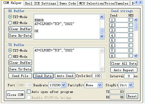
| + | Input the following code in the text box of "TX Buffer" and then press "Enter". | ||
| + | |||
| + | AT+CLPORT="TCP","2022" | ||
| + | |||
| + | Click "Send Data". If the "RX Buffer" shows "ok", it is successful. | ||
| + | |||
| + | OK | ||
| + | |||
| + | [[File:Gprs (3).jpg|500px|]] | ||
| + | |||
| + | [[File:Gprs (4).jpg|500px|]] | ||
| + | |||
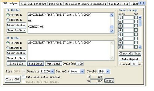
| + | Input in "TX Buffer" as follows, | ||
| + | |||
| + | |||
| + | AT+CIPSTART="TCP","183.37.246.171","10000" | ||
| + | |||
| + | (NB.IP “183.37.246.171” is a Public IP from Google; “10000” is the “Local Host Port”). | ||
| + | And then click "Send Data". The "RX Buffer" will appear | ||
| + | |||
| + | OK | ||
| + | CONNECT OK | ||
| + | |||
| + | as follows, which means the data has been sent successfully. | ||
| + | Now it can realize the TCP communication. | ||
| + | |||
| + | [[File:Gprs6.jpg|500px|]] | ||
| + | |||
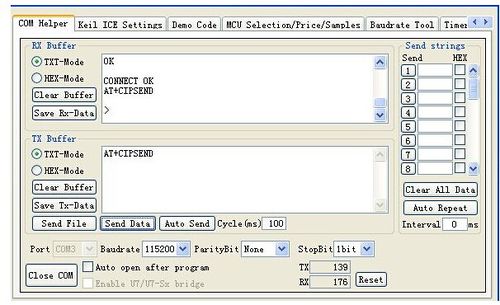
| + | 3, Verify the success of communication | ||
| + | Input | ||
| + | |||
| + | AT+CIPSEND | ||
| + | |||
| + | in "TX Buffer", then press "Enter". Click "Send Data" and the "RX Buffer" appears | ||
| + | |||
| + | > | ||
| + | |||
| + | as follows. | ||
| + | |||
| + | [[File:Gprs7.jpg|500px|]] | ||
| + | |||
| + | Input | ||
| + | |||
| + | HELLO WORLD | ||
| + | |||
| + | in "TX Buffer" and click "Send Data", check "HEX-Mode". | ||
| + | |||
| + | Meanwhile, input | ||
| + | |||
| + | 1A | ||
| + | |||
| + | to end instruction and click "Send Data". It is successful when you see | ||
| + | |||
| + | SEND OK | ||
| + | |||
| − | + | [[File:Gprs8.jpg|500px|]] | |
| + | |||
| + | [[File:Gprs9.jpg|500px|]] | ||
| + | |||
| + | Now,"Helloword" will appear in "NetAssist". | ||
| + | |||
| + | [[File:Gprs10.jpg|500px|]] | ||
| + | |||
| + | Select the corresponding IP address and click "Send". | ||
| + | "RX Buffer" dialog in STC-ISP will accept the information returned as below. | ||
| + | |||
| + | |||
| + | [[File:Gprs11.jpg|500px|]] | ||
| + | |||
| + | |||
| + | PS: | ||
| − | + | [[Media:For gprs networking test.rar]] | |
== How to buy == | == How to buy == | ||
| − | GPRS Shield | + | Click here to buy [http://www.geeetech.com/gprsgsm-sim900-shield-board-arduino-compatible-p-610.html Arduino GPRS Shield ] |
Latest revision as of 09:53, 8 July 2014
Contents
- 1 Introduction
- 2 Features
- 3 Application Ideas
- 4 Cautions
- 5 Hardware Diagram
- 6 Getting Started
- 7 Schematics
- 8 Resources
- 9 instructions to test the communication
- 10 How to buy
Introduction
The GPRS Shield is based on SIM900 module from SIMCOM and compatible with Arduino and its clones. The GPRS Shield provides you a way to communicate using the GSM cell phone network. The shield allows you to achieve SMS, MMS, GPRS and Audio via UART by sending AT commands (GSM 07.07 ,07.05 and SIMCOM enhanced AT Commands). The shield also has the 12 GPIOs, 2 PWMs and an ADC of the SIM900 module(They are all 2V8 logic) present onboard.
Features
- Quad-Band 850 / 900/ 1800 / 1900 MHz - would work on GSM networks in all countries across the world.
- GPRS multi-slot class 10/8
- GPRS mobile station class B
- Compliant to GSM phase 2/2+
- Class 4 (2 W @ 850 / 900 MHz)
- Class 1 (1 W @ 1800 / 1900MHz)
- Control via AT commands - Standard Commands: GSM 07.07 & 07.05 | Enhanced Commands: SIMCOM AT Commands.
- Short Message Service - so that you can send small amounts of data over the network (ASCII or raw hexadecimal).
- Embedded TCP/UDP stack - allows you to upload data to a web server.
- RTC supported.
- Selectable serial port.
- Speaker and Headphone jacks
- Low power consumption - 1.5mA(sleep mode)
- Industrial Temperature Range - -40°C to +85 °C
Specifications
Application Ideas
- M2M (Machine 2 Machine) Applicatoions.
- Remote control of appliances.
- Remote Weather station or a Wireless Sensor Network.
- Vehicle Tracking System with a GPS module.
Cautions
- Make sure your SIM card is unlocked.
- The product is provided as is without an insulating enclosure. Please observe ESD precautions specially in dry (low humidity) weather.
- The factory default setting for the GPRS Shield UART is 19200 bps 8-N-1. (Can be changed using AT commands).
Hardware Diagram
- Power select - select the power supply for GPRS shield(external power or 5v of arduino)
- Power jack - connected to external 4.8~5VDC power supply
- Antenna interface - connected to external antenna
- Serial port select - select either software serial port or hareware serial port to be connected to GPRS Shield
- Hardware Serial - D0/D1 of Arduino
- Software serial - D7/D8 of Arduino
- Status LED - tell whether the power of SIM900 is on
- Net light - tell the status about SIM900 linking to the net
- UART of SIM900 - UART pins breakout of SIM900
- Microphone - to answer the phone call
- Speaker - to answer the phone call
- GPIO,PWM and ADC of SIM900 - GPIO,PWM and ADC pins breakout of SIM900
- Power key - power up and down for SIM900
- Pins usage on Arduino
- D0 - Unused if you select software serial port to communicate with GPRS Shield
- D1 - Unused if you select software serial port to communicate with GPRS Shield
- D2 - Unused
- D3 - Unused
- D4 - Unused
- D5 - Unused
- D6 - Unused
- D7 - Used if you select software serial port to communicate with GPRS Shield
- D8 - Used if you select software serial port to communicate with GPRS Shield
- D9 - Used for software control the power up or down of the SIM900
- D10 - Unused
- D11 - Unused
- D12 - Unused
- D13 - Unused
- D14(A0) - Unused
- D15(A1) - Unused
- D16(A2) - Unused
- D17(A3) - Unused
- D18(A4) - Unused
- D19(A5) - Unused
- Note: A4 and A5 are connected to the I2C pins on the SIM900. The SIM900 however cannot be accessed via the I2C .
Getting Started
- Insert a unlock SIM card
- Make sure the antenna pad buckled properly
- Assemble the GSM antenna
- Chooose communication port properly using the jumpers
- Assemble GPRS shield to Arduino and download the sketch
- Press power key about 2 seconds to turn on the GPRS shield
Indicator LEDs
There are three indicator LEDs(PWR(Green), Staus(Blue), Netlight(Red)) on the GPRS Shield, users can know about the working state of the shield based on the three indicator LEDs. Detailed information please refer to the following table:
Power Up and Power Down the GPRS Shield
Power Up the GPRS Shield
The GPRS Shield can be turned on by two ways:
- 1, Hardware Triger; Press the ON/OFF Button about two seconds.The power up scenarios illustrates as following figure:
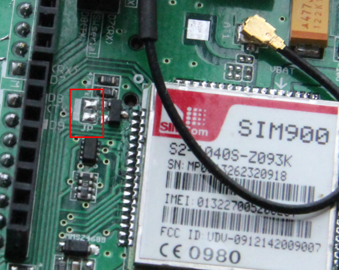
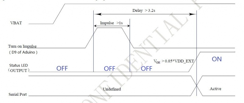
- 2, Software Triger; If use this way to power up the GPRS Shield, JP need to be soldered, then Digital Pin 9 of the Arduino will act as Software Triger port and Digital Pin 9 can not be use as other purpose. Then give Digital Pin 9 a Turn on Impulse can power up the GPRS Shield. The power up scenarios illustrates as following figure:
The following code is power up subroutine for Arduino if using software triger:
void powerUp()
{
 pinMode(9, OUTPUT);
 digitalWrite(9,LOW);
 delay(1000);
 digitalWrite(9,HIGH);
 delay(2000);
 digitalWrite(9,LOW);
 delay(3000);
}
When power on procedure completes, the SIM900 will send out following result code to indicate the GPRS shield is ready to operate; When set as fixed baud rate, the SIM900 will send out result code: RDY This result code does not appear when auto baud rate is active.
Power Down the GPRS Shield
The GPRS Shield can be turned off by following ways:
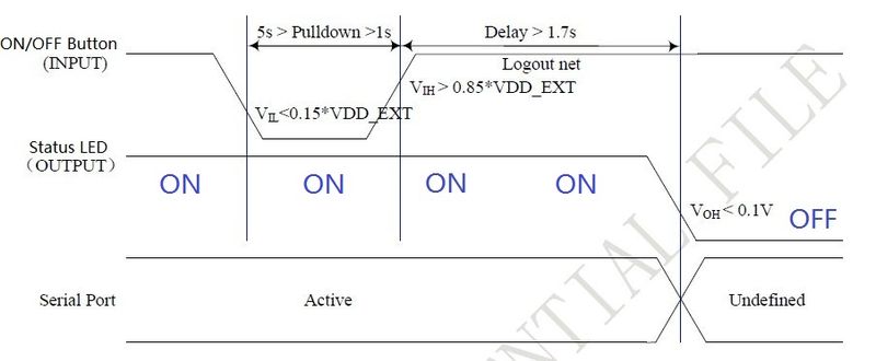
- 1, Normal power down procedure: Turn off the GPRS shield by using Hardware Triger; Press the ON/OFF Button about two seconds.
The power down scenarios illustrates as following figure:
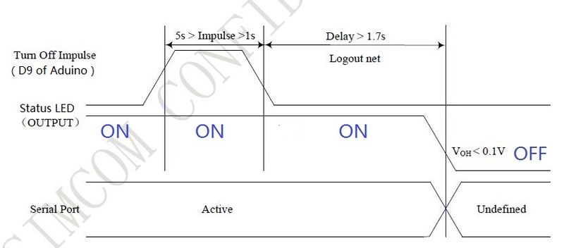
2, Normal power down procedure: If JP is soldered, then give Digital Pin 9 of the Arduino(act as Software Triger) a Turn off Impulse can turn off the GPRS Shield. The power down scenarios illustrates as following figure:
The following code is power down subroutine for Arduino if using software triger:
void powerDown()
{
 pinMode(9, OUTPUT);
 digitalWrite(9,LOW);
 delay(1000);
 digitalWrite(9,HIGH);
 delay(2000);
 digitalWrite(9,LOW);
 delay(3000);
}
- 3, Normal power down procedure:Turn off the GPRS shield by sending AT command “AT+CPOWD=1” to SIM900 module.
When GPRS Shield power dowm in Normal power down procedure, the procedure lets the SIM900 log off from the network and allows the software to enter into a secure state and save data before completely disconnecting the power supply. Before the completion of the power down procedure the SIM900 will send out result code: NORMAL POWER DOWN
- 4, Over-voltage or Under-voltage Automatic Power Down: SIM900 will constantly monitor the voltage applied on the VBAT.
①If the voltage ≤ 3.3V, the following URC will be presented:
UNDER-VOLTAGE WARNNING
②If the voltage ≥ 4.7V, the following URC will be presented:
OVER-VOLTAGE WARNNING
③The uncritical voltage range is 3.2V to 4.8V. If the voltage > 4.8V or < 3.2V, SIM900 will be automatic power down soon. If the voltage < 3.2V, the following URC will be presented:
UNDER-VOLTAGE POWER DOWN
④If the voltage > 4.8V, the following URC will be presented:
OVER-VOLTAGE POWER DOWN
- 5, Over-temperature or Under-temperature Automatic Power Down: SIM900 will constantly monitor the temperature of the module.
①If the temperature > 80℃, the following URC will be presented:
+CMTE:1
②If the temperature < -30℃, the following URC will be presented:
+CMTE:-1
③The uncritical temperature range is -40℃ to +85℃. If the temperature > +85℃ or < -40℃, the module will be automatic power down soon. If the temperature > +85℃, the following URC will be presented:
+CMTE:2
④If the temperature < -40℃, the following URC will be presented:
+CMTE:-2
When the GPRS Shield encounters POWER DOWN scenario, the AT commands can not be executed. The SIM900 logs off from network and enters the POWER DOWN mode, only the RTC is still active. POWER DOWN can also be indicated by STATUS LED(Blue), which is off in this mode.
Note:
- To monitor the temperature, users can use the “AT+CMTE” command to read the temperature when GPRS Shield is powered on.
- To monitor the supply voltage, users can use the “AT+CBC” command which includes a parameter: voltage value(in mV) when GPRS Shield is powered on.
Serial Port(UART) Communication
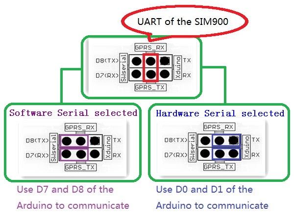
The GPRS Shield is used UART protocol to communicate with an Arduino/Arduino clone; Users can use jumpers to connect (RX,TX) of the shield to either Software Serial(D8,D7) or Hardware Serial(D1,D0) of the Arduino.Detailed information is showed as the following picture:
Note:
- Not all Arduino boards support software serial on D7 and D8, For example Arduino Mega and Mega 2560 only support the following pins for RX: 10, 11, 12, 13, 50, 51, 52, 53, 62, 63, 64, 65, 66, 67, 68, 69. So Arduino Mega doesn't support soft serial on Pin D7 and D8. If using GPRS shield with Ardiuno Mega, please use the hardware serial or use the jumper wires wiring GPRS TX and RX to the pins support interrupt on Ardiuno Mega. And not all pins on the Leonardo support change interrupts, so only the following can be used for RX: 8, 9, 10, 11, 14 (MISO), 15 (SCK), 16 (MOSI). More information about Softserial library please visit http://arduino.cc/en/Reference/SoftwareSerial
- Users can use “AT+IPR=?” command to see supported baudrate, it will response a list of supported baudrate.
- Users can use “AT+IPR=x”(x is value of supported baudrate) to set a fixed baud rate and save the configuration to non-volatile flash memory.
Upload Sketch to Arduino
The following sketch configures Arduino/Arduino clone as serial link between PC and the GPRS Shield(Jumpers on SWserial side). PC would need a serial terminal software to communicate with it - Window's built-in HyperTerminal, Arduino IDE's Serial Monitor, Serial Terminals(sscom32) or Bray++ Terminal.
The GPRS Shield comes with all the accessories that you need to get started with sending data over the GSM network except an Arduino board and a GSM SIM Card. If you want to make voice calls, you would also require a headset with microphone.
Step 1: Creating a test setup for the GPRS Shield
AT Commands are simple textual commands sent to the GPRS modem over its serial interface (UART), so you can use any serial terminal software to communicate with it.
Note: Almost all the AT commands should be sent followed by carriage return and you need to select the "+CR"option in the serial port terminal.To experiment with AT commands, you would require a way to power up and communicate with your GPRS Shield. The best way to do this using an Arduino Duemilanove board.
- Follow the previously described hardware installation steps to set up the hardware system;
- Make sure the GPRS_TX & GPRS_RX jumpers on the GPRS Shield are mounted in SWSerial position - that is we want GPRS_TX to be connected to D7(RX) and GPRS_RX to D8(TX).
- Connect the Arduino Duemilanove to your computer using a USB cable.
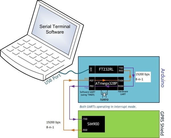
- The ATmega328P microcontroller on Duemilanove board has only one UART which is used for communicating with the PC. What we need is an Arduino Sketch running inside the ATmega328P that would emulate a second serial port (UART) using software on the digital pins D8 and D7 and patch through all the communication between this second software serial port and the actual hardware serial port. By doing this, all the data coming from the computer (connected to the actual hardware UART) would be routed to the GPRS Shield (connected to software UART) then, we would be able to issue AT commands to control the GPRS Shield. The block diagram outlining this scheme is shown below.
For developing such a program, we require to use the SoftwareSerial library included in the libraries of Arduino 1.0 already and the demo code below.
//Serial Relay - Arduino will patch a
//serial link between the computer and the GPRS Shield
//at 19200 bps 8-N-1
//Computer is connected to Hardware UART
//GPRS Shield is connected to the Software UART
#include <SoftwareSerial.h>
SoftwareSerial GPRS(7, 8);
unsigned char buffer[64]; // buffer array for data recieve over serial port
int count=0;     // counter for buffer array
void setup()
{
 GPRS.begin(19200);               // the GPRS baud rate
 Serial.begin(19200);             // the Serial port of Arduino baud rate.
}
void loop()
{
 if (GPRS.available())              // if date is comming from softwareserial port ==> data is comming from gprs shield
 {
   while(GPRS.available())          // reading data into char array
   {
     buffer[count++]=GPRS.read();     // writing data into array
     if(count == 64)break;
 }
   Serial.write(buffer,count);            // if no data transmission ends, write buffer to hardware serial port
   clearBufferArray();              // call clearBufferArray function to clear the storaged data from the array
   count = 0;                       // set counter of while loop to zero
 }
 if (Serial.available())            // if data is available on hardwareserial port ==> data is comming from PC or notebook
   GPRS.write(Serial.read());       // write it to the GPRS shield
}
void clearBufferArray()              // function to clear buffer array
{
 for (int i=0; i<count;i++)
   { buffer[i]=NULL;}                  // clear all index of array with command NULL
}
- .Upload the sketch to the Arduino board.
- .Download and fire up serial tool if you don't have one. Choose the correct COM port for Arduino, and set it to operate at 19200 8-N-1 and then click "Open Com".
- .You can power on or off the the SIM900 by pressing the button about 2 second. After power on, the red LED will be on, and the green one beside it will blink and the shield has found the net if it blinks every 3 seconds.
Also, in the serial monitor you should see messages from the shield such as RDY
+CFUN: 1
+CPIN: READY
Call Ready
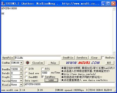
If you can not see the messages in the serial monitor, you should click the "send new" option that will add carriage return at the end of AT command and then send AT command "AT+IPR=19200" to set the baud rate of the SIM900.
- Step 2: Sending a text message (SMS)
Now that our test setup is ready, let's play around with some AT Commands manually before moving on to programming the Arduino to do this. Let's try sending an SMS to start.
- .Create the setup as described in Step 1 above.
- .Through your serial terminal software, send AT+CMGF=1 and press the Enter key. The GPRS Shield can send SMSes in two modes: Text mode and PDU (or binary) mode. Since we want to send out a human readable message, we will select the text mode. The GPRS Shield will respond with an OK.
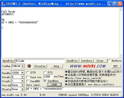
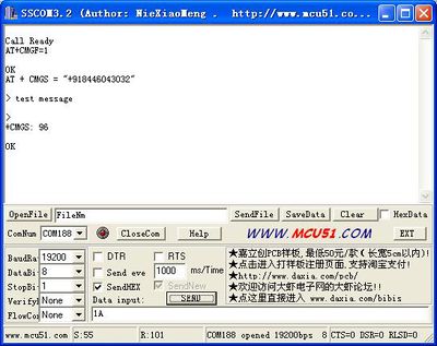
- .Click "send new" option and send AT+CMGS="+918446043032". This will instruct the GPRS Shield to start accepting text for a new message meant for the phone number specified (replace the number with the phone number of the target phone). The GPRS Shield will send a > to remind you typing the message.
- .Start typing your message and when you are done, and click "send hex" option and then send a hex: 1A. The modem will accept the message and respond with an OK. A few moments later, the message should be received on the handset whose number you had specified.You can refer to the picture below.
NOTE: If, in spite of following the steps as specified above, you aren't able to receive the message on the target handset, then it might be that you need to set the SMS Message Center number. Send the command AT+CSCA="+919032055002" and press the Enter Key. Send this command in between the AT+CMGF and AT+CMGS commands. Replace the phone number specified in the command above with the SMS Center number of your GSM Service Provider. The message center number is specific to each service provider (for example +919032055002 is the message center number for Tata DoCoMo, Pune, India). You can get the message center number by calling up the customer care center of the GSM Service Provider and asking them for it.
SoftwareSerial library Notes
With Arduino 1.0 you should be able to use the SoftwareSerial library included with the distribution (instead of NewSoftSerial). However, you must be aware that the buffer reserved for incoming messages are hardcoded to 64 bytes in the library header, "SoftwareSerial.h": 1.define _SS_MAX_RX_BUFF 64 // RX buffer size
This means that if the GPRS module responds with more data than that, you are likely to loose it with a buffer overflow! For instance, reading out an SMS from the module with "AT+CMGR=xx" (xx is the message index), you might not even see the message part because the preceding header information (like telephone number and time) takes up a lot of space. The fix seems to be to manually change _SS_MAX_RX_BUFF to a higher value (but reasonable so you don't use all you precious memory!)
The Softwareserial library has the following limitations (taken from arduino page) If using multiple software serial ports, only one can receive data at a time. http://arduino.cc/hu/Reference/SoftwareSerial This means that if you try to add another serial device ie grove serial LCD you may get communication errors unless you craft your code carefully.
A Simple Source Code Examples
The demo code below is for the Xduino to send SMS message/dial a voice call/submit a http request to a website and upload datas to the pachube. It has been tested on Arduino Duemilanove but will work on any compatible variant, plesse note that this sketch uses the sorfware UART of ATmega328P. please follow the following steps for running this sketch.
- .With the GPRS Shield removed, download this sketch into your Arduino.
- .Disconnect the Xduino from USB port to remove power source.
- .Set the Serial Port jumpers on the GPRS Shield in SWserial position, to use the Soft Serial port of Arduino.
- .Connect the antenna to the GPRS Shield and insert the SIM Card.
- .Mount the GPRS Shield on Arduino.
- .Connect the Arduino to the computer by USB, and fire up your favorite serial terminal software on computer, choose the COM port for Arduino, set it to operate at 19200 8-N-1.
- .Type command in the terminal to execute different function, threr are 4 functions in the demo:
- .If you input 't', the demo will send a SMS message to another cellphone which you set(you need set the number in the code);
- .If you input 'd', the program will dial a call to the other cellphone that you set(it is also need you set in the code );
- .If you input 'h', it will submit a http request to a web that you want to access(it need you set the web adress in the code), it will return a string from the website if it goes correctly;
- .If you input 's', it will upload the datas to the pachube(for detail you can refer to the explanation in the code). I strongly recommend you input 'h' before input 's', because uploading datas to the pachube need do some setting, after execute the function of submit a http request, the setting will be set.
- .If the program returns error in the terminal after you typed the command, don't worry, just try input the command again.
/*Note: this code is a demo for how to using gprs shield to send sms message, dial a voice call and
 send a http request to the website, upload data to pachube.com by TCP connection,

 The microcontrollers Digital Pin 7 and hence allow unhindered
 communication with GPRS Shield using SoftSerial Library.
 IDE: Arduino 1.0 or later
 Replace the following items in the code:
 1.Phone number, don't forget add the country code
 2.Replace the Access Point Name
 3. Replace the Pachube API Key with your personal ones assigned
 to your account at cosm.com
 */
#include <SoftwareSerial.h>
#include <String.h>
SoftwareSerial mySerial(7, 8);
void setup()
{
 mySerial.begin(19200);               // the GPRS baud rate
 Serial.begin(19200);    // the GPRS baud rate
 delay(500);
}
void loop()
{
 //after start up the program, you can using terminal to connect the serial of gprs shield,
 //if you input 't' in the terminal, the program will execute SendTextMessage(), it will show how to send a sms message,
 //if input 'd' in the terminal, it will execute DialVoiceCall(), etc.
  if (Serial.available())
   switch(Serial.read())
  {
    case 't':
      SendTextMessage();
      break;
    case 'r':
      RecieveTextMessage();//This program code by directive'r'to receive, by receiving the information after the return to call the function
                           //to verify receiving function. But it can not display the received content in SIM.
      DialVoiceCall();
      break;
    case 'd':
      DialVoiceCall();
      break;
    case 'h':
      SubmitHttpRequest();
      break;
    case 's':
      Send2Pachube();
      break;
  }
 if (mySerial.available())
   Serial.write(mySerial.read());
}
///SendTextMessage()
///this function is to send a sms message
 void SendTextMessage()
{
 mySerial.print("AT+CMGF=1\r");    //Because we want to send the SMS in text mode
 delay(100);
 mySerial.println("AT + CMGS = \"+86138xxxxx615\"");//send sms message, be careful need to add a country code before the cellphone number
 delay(100);
 mySerial.println("A test message!");//the content of the message
 delay(100);
 mySerial.println((char)26);//the ASCII code of the ctrl+z is 26
 delay(100);
 mySerial.println();
}
 void RecieveTextMessage()
  {
  //mySerial.print("AT+CMGF=1\r"); //Because we want to recieve the SMS in text mode
 //delay(100);
   mySerial.print("AT+CMGR=1\r");//Because we want to recieve the SMS in text mode
   delay(100);
   mySerial.println("AT + CSCA = \"+86135*********\"");//recieve sms message, be careful need to add a country code before the cellphone number
   delay(100);
   mySerial.println("A test message!");//the content of the message
   delay(100);
   mySerial.println((char)26);//the ASCII code of the ctrl+z is 26
   delay(100);
   mySerial.println();
 //return r;
 }
///DialVoiceCall
///this function is to dial a voice call
void DialVoiceCall()
{
 mySerial.println("ATD + +86138xxxxx615;");//dial the number
 delay(100);
 mySerial.println();
}
///SubmitHttpRequest()
///this function is submit a http request
///attention:the time of delay is very important, it must be set enough
void SubmitHttpRequest()
{
 mySerial.println("AT+CSQ");
 delay(100);
 ShowSerialData();// this code is to show the data from gprs shield, in order to easily see the process of how the gprs shield submit a http request, and the following is for this purpose too.
 mySerial.println("AT+CGATT?");
 delay(100);
 ShowSerialData();
 mySerial.println("AT+SAPBR=3,1,\"CONTYPE\",\"GPRS\"");//setting the SAPBR, the connection type is using gprs
 delay(1000);
 ShowSerialData();
 mySerial.println("AT+SAPBR=3,1,\"APN\",\"CMNET\"");//setting the APN, the second need you fill in your local apn server
 delay(4000);
 ShowSerialData();
 mySerial.println("AT+SAPBR=1,1");//setting the SAPBR, for detail you can refer to the AT command mamual
 delay(2000);
 ShowSerialData();
 mySerial.println("AT+HTTPINIT"); //init the HTTP request
 delay(2000);
 ShowSerialData();
 mySerial.println("AT+HTTPPARA=\"URL\",\"www.google.com.hk\"");// setting the httppara, the second parameter is the website you want to access
 delay(1000);
 ShowSerialData();
 mySerial.println("AT+HTTPACTION=0");//submit the request
 delay(10000);//the delay is very important, the delay time is base on the return from the website, if the return datas are very large, the time required longer.
 //while(!mySerial.available());
 ShowSerialData();
 mySerial.println("AT+HTTPREAD");// read the data from the website you access
 delay(300);
 ShowSerialData();
 mySerial.println("");
 delay(100);
}
///send2Pachube()///
///this function is to send the sensor data to the pachube, you can see the new value in the pachube after execute this function///
void Send2Pachube()
{
 mySerial.println("AT+CGATT?");
 delay(100);
 ShowSerialData();
 mySerial.println("AT+CSTT=\"CMNET\"");//start task and setting the APN,
 delay(1000);
 ShowSerialData();
 mySerial.println("AT+CIICR");//bring up wireless connection
 delay(300);
 ShowSerialData();
 mySerial.println("AT+CIFSR");//get local IP adress
 delay(2000);
 ShowSerialData();
 mySerial.println("AT+CIPSPRT=0");
 delay(3000);
 ShowSerialData();
 mySerial.println("AT+CIPSTART=\"tcp\",\"api.cosm.com\",\"8081\"");//start up the connection
 delay(2000);
 ShowSerialData();
 mySerial.println("AT+CIPSEND");//begin send data to remote server
 delay(4000);
 ShowSerialData();
 String humidity = "1031";//these 4 line code are imitate the real sensor data, because the demo did't add other sensor, so using 4 string variable to replace.
 String moisture = "1242";//you can replace these four variable to the real sensor data in your project
 String temperature = "30";//
 String barometer = "60.56";//
 mySerial.print("{\"method\": \"put\",\"resource\": \"/feeds/42742/\",\"params\"");//here is the feed you apply from pachube
 delay(500);
 ShowSerialData();
 mySerial.print(": {},\"headers\": {\"X-PachubeApiKey\":");//in here, you should replace your pachubeapikey
 delay(500);
 ShowSerialData();
 mySerial.print(" \"_cXwr5LE8qW4a296O-cDwOUvfddFer5pGmaRigPsiO0");//pachubeapikey
 delay(500);
 ShowSerialData();
 mySerial.print("jEB9OjK-W6vej56j9ItaSlIac-hgbQjxExuveD95yc8BttXc");//pachubeapikey
 delay(500);
 ShowSerialData();
 mySerial.print("Z7_seZqLVjeCOmNbEXUva45t6FL8AxOcuNSsQS\"},\"body\":");
 delay(500);
 ShowSerialData();
 mySerial.print(" {\"version\": \"1.0.0\",\"datastreams\": ");
 delay(500);
 ShowSerialData();
 mySerial.println("[{\"id\": \"01\",\"current_value\": \"" + barometer + "\"},");
 delay(500);
 ShowSerialData();
 mySerial.println("{\"id\": \"02\",\"current_value\": \"" + humidity + "\"},");
 delay(500);
 ShowSerialData();
 mySerial.println("{\"id\": \"03\",\"current_value\": \"" + moisture + "\"},");
 delay(500);
 ShowSerialData();
 mySerial.println("{\"id\": \"04\",\"current_value\": \"" + temperature + "\"}]},\"token\": \"lee\"}");
 delay(500);
 ShowSerialData();
 mySerial.println((char)26);//sending
 delay(5000);//waitting for reply, important! the time is base on the condition of internet
 mySerial.println();
 ShowSerialData();
 mySerial.println("AT+CIPCLOSE");//close the connection
 delay(100);
 ShowSerialData();
}
void ShowSerialData()
{
 while(mySerial.available()!=0)
   Serial.write(mySerial.read());
}
Schematics
Resources
SIM900 AT Commands Manual v1.03.pdf
SIM900_hd_v1.06.pdf
SIM900_TCP/IP Application Note
Si5902BDC - Dual N-Channel 30 V (D-S) MOSFETs (used for 2.8V <> 5.0V translation for Serial Interface)
instructions to test the communication
If you are using a Router rather than a modem or Exchanger, before networking testing for the GPRS module, you should pay attention to the following tips.
1. Specify a fixed IP address for Local Host,hereinafter referred to as "Local Host IP".
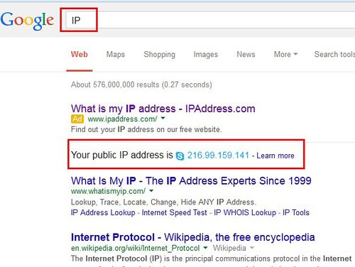
2. Set a Port Mapping on the Router and map the port to Local Host IP. We call the set port "Local Host Port". Local Host Port is within 0 and 65535.
3. Open home page (Google), input "IP" to check your Public IP.
FAQS
Q1. Why should I specify a "Local Host Port" on the Router (Port Mapping)?
ADSL dials through a router and the host shares network through the router. In this case, the host usually extracts Private IP such as 192.168.x.x. for such reasons, only when you specify a ‘Local Host Port’ on the Router (Port Mapping) and forward it to the corresponding Local Host, can the Internet access to the Local Host through this Port.
Q2. Why should I specify a Fixed Private IP for the Local Host?
Port Mapping is a one-to-one process. If the Local Host is specified to obtain IP automatically, the IP address will probably change when the computer restarts or reconnects to the network. Therefore, it is necessary to specify a Fixed Private IP.
Tools
1. Arduino IDE
2. Net Assist
3. STC-SIP
Steps
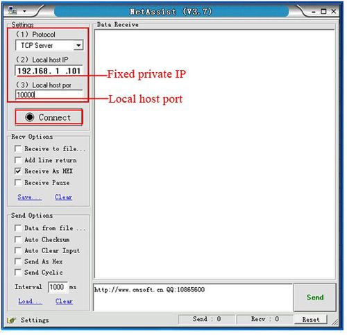
1, Start the "Net Assist", choose "TCP server" in the dropdown menus of "protocol" (UDP Server is not recommended), change the "Local Host IP" into the Fixed IP. Input the "Local host port" set before and then click “Connect “. As shown in following the picture.
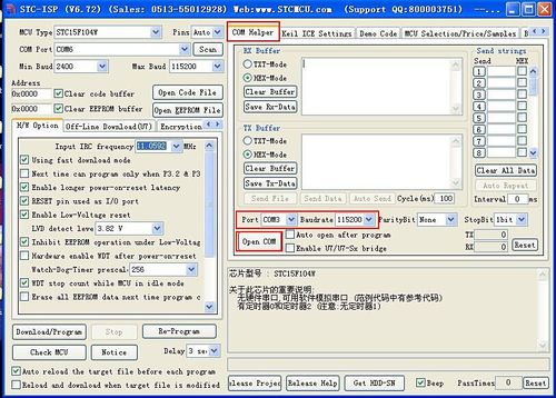
2, Open STC-ISP and click "COM Helper" Click "COM Port" and click 115200 in "Baud rate" ( if the code is unreadable in RX Buffer, then re-click Baud rate) , click "Open COM"
Input the following code in the text box of "TX Buffer" and then press "Enter".
AT+CLPORT="TCP","2022"
Click "Send Data". If the "RX Buffer" shows "ok", it is successful.
OK
Input in "TX Buffer" as follows,
AT+CIPSTART="TCP","183.37.246.171","10000"
(NB.IP “183.37.246.171” is a Public IP from Google; “10000” is the “Local Host Port”). And then click "Send Data". The "RX Buffer" will appear
 OK
 CONNECT OK
as follows, which means the data has been sent successfully. Now it can realize the TCP communication.
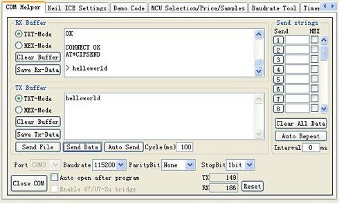
3, Verify the success of communication Input
AT+CIPSEND
in "TX Buffer", then press "Enter". Click "Send Data" and the "RX Buffer" appears
>
as follows.
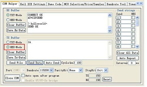
Input
HELLO WORLD
in "TX Buffer" and click "Send Data", check "HEX-Mode".
Meanwhile, input
1A
to end instruction and click "Send Data". It is successful when you see
SEND OK
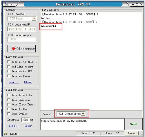
Now,"Helloword" will appear in "NetAssist".
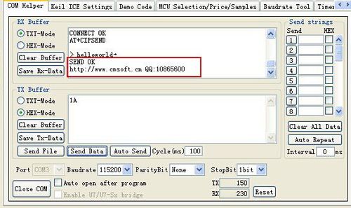
Select the corresponding IP address and click "Send". "RX Buffer" dialog in STC-ISP will accept the information returned as below.
PS:
Media:For gprs networking test.rar
How to buy
Click here to buy Arduino GPRS Shield
