Difference between revisions of "Debug king(3-IN-1) Debug card"
(→DEBUG KING (3-IN-1) USER GUIDE) |
(→DEBUG KING (3-IN-1) USER GUIDE) |
||
| (4 intermediate revisions by the same user not shown) | |||
| Line 1: | Line 1: | ||
== DEBUG KING (3-IN-1) USER GUIDE == | == DEBUG KING (3-IN-1) USER GUIDE == | ||
| − | [[File:Debug 3-in-1.jpg|400px | + | [[File:Debug 3-in-1.jpg|400px]] |
| − | DEBUG KING (3-IN-1) is upgraded version of the Three –IN-One Notebook Debug card, and it is composed by two parts: | + | [http://www.geeetech.com/laptop-mini-pcie-pc-pci-diagnostic-p-431.html DEBUG KING (3-IN-1)] is upgraded version of the Three –IN-One Notebook Debug card, and it is composed by two parts: |
DEBUG KING HOST and 3-IN-1 INTERPOSER.DEBUG KING HOST is powered by USB port, and using LCD to display English and photos. Also, it supports the debug code feature so that users can be easy to find the different debug code English description. The 3-IN-1 INTERPOSER supports note book MiniPCI and LPC bus interface. DEBUG KING HOST gets notebook debug code from 3-IN-1 INTERPOSER, and then shows the corresponding English or Photos information based on the debug code, and also gives their repair suggestion. With DEBUG KING (3-IN-1), Users don’t need to remember the meaning of every debug code, and DEBUG KING can show it to user directly, It is convenient for uses to fix their computer issues quickly. | DEBUG KING HOST and 3-IN-1 INTERPOSER.DEBUG KING HOST is powered by USB port, and using LCD to display English and photos. Also, it supports the debug code feature so that users can be easy to find the different debug code English description. The 3-IN-1 INTERPOSER supports note book MiniPCI and LPC bus interface. DEBUG KING HOST gets notebook debug code from 3-IN-1 INTERPOSER, and then shows the corresponding English or Photos information based on the debug code, and also gives their repair suggestion. With DEBUG KING (3-IN-1), Users don’t need to remember the meaning of every debug code, and DEBUG KING can show it to user directly, It is convenient for uses to fix their computer issues quickly. | ||
| Line 48: | Line 48: | ||
== The Structure of 3-IN-1 INTERPOSER == | == The Structure of 3-IN-1 INTERPOSER == | ||
| + | [[File:Interposer.jpg|400px]] | ||
| + | |||
| + | |||
[[File:3-in-1 interposer.gif]] | [[File:3-in-1 interposer.gif]] | ||
Latest revision as of 03:14, 22 February 2012
Contents
- 1 DEBUG KING (3-IN-1) USER GUIDE
- 2 The Structure of DEBUG KING HOST
- 3 The USB port of DEBUG KING HOST
- 4 The LED indicator of DEBUG KING HOST
- 5 The Buttons of DEBUG KING HOST
- 6 The LCD Display in DEBUG KING HOST
- 7 How to upgrade the DEBUG CODE English Description
- 8 The Structure of 3-IN-1 INTERPOSER
- 9 The Mini PCI-E Interface in 3-IN-1 INTERPOSER
- 10 The Mini PCI Interface in 3-in-1 INTERPOSER
- 11 The LPC interface in 3-IN-1 INERPOSER
- 12 DEBUG KING (3-in-1) Offline Use guide
- 13 DEBUG KING (3-in-1) Online Use guide
DEBUG KING (3-IN-1) USER GUIDE
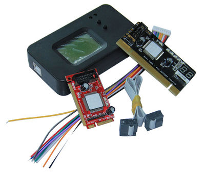
DEBUG KING (3-IN-1) is upgraded version of the Three –IN-One Notebook Debug card, and it is composed by two parts: DEBUG KING HOST and 3-IN-1 INTERPOSER.DEBUG KING HOST is powered by USB port, and using LCD to display English and photos. Also, it supports the debug code feature so that users can be easy to find the different debug code English description. The 3-IN-1 INTERPOSER supports note book MiniPCI and LPC bus interface. DEBUG KING HOST gets notebook debug code from 3-IN-1 INTERPOSER, and then shows the corresponding English or Photos information based on the debug code, and also gives their repair suggestion. With DEBUG KING (3-IN-1), Users don’t need to remember the meaning of every debug code, and DEBUG KING can show it to user directly, It is convenient for uses to fix their computer issues quickly.
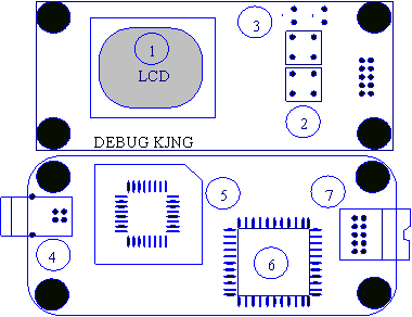
The Structure of DEBUG KING HOST
- Debug King LCD Screen to show English and Photos
- Debug King buttons to change the debug code or BIOS type
- Debug King LED Indicator to show the working mode
- Debug King USB port to be used to provide power
- Debug King EEPROM chip to save English and Photos data
- Debug King ASIC to deal with signals
- Debug King External Port to connect 3-in-1 Interposer
The USB port of DEBUG KING HOST
Debug King is power by USB port. After connect Debug king to the computer’s USB port, Debug King enters offline working mode.
The LED indicator of DEBUG KING HOST
There are two LED indicator in the top right corner of debug king. When the left LED is on, it means Debug King is in offline mode, and 3-in-1 Interposer isn’t connected yet. When the right LED is on, it means Debug King is in online mode, and 3-in-1 Interposer has been connected.
The Buttons of DEBUG KING HOST
Debug King Buttons are used to change debug code, When in offline mode, one button is used to change the ten digits, another is used to change the lowest digit. With this , users can quickly find the English description of every debug code. When in online mode, these two buttons are used for page- up and page-down feature.
The different motherboard may use different BOIS types. Currently, the BIOS type include AMI, AWARD, and Phoenix. Before using debug king, users need to set correct BIOS type first. When switching BIOS type, first, pushing the up-button, then pushing the down-button without releasing the up-bottom, the BIOS type switching information will show in the LCD screen.
When pushing the down-button first, then pushing the up-button, Debug will show the product SN number and register code.
The LCD Display in DEBUG KING HOST
5: The LCD Display in DEBUG KING HOST
Debug king uses LCD screen to show English or Photos information. When Debug King is powered on, it will show the information as below. DEBUG KING Version includes two parts;
- The left side of dot is the firmware version
- The right side of the dot is the Debug code English description message version.
In offline mode, when pushing any of the buttons, users can read the debug code description of every debug code. In the bottom-right corner, Debug King will show the debug code as “XX”, which is the same as the traditional LED debug code number. A letter is followed up after the number to show the BIOS type. Usually, “m” means AMI BIOS. “W” means AWARD BIOS, “P” means PHOENIX BIOS, and “u” means AUTO BIOS is debug King’s Smart BIOS Code, Debug King uses English description for AMI/AWARD/PHOENIX BIOS, and use Photos for Auto Bios, Please refer the appendix part to get more information about AUTO BIOS.
How to upgrade the DEBUG CODE English Description
Because motherboard technology development is so quickly, the debug code description may also be changed with time passing. Debug king allows users to upgrade the debug description themselves
All debug King and photos description is saved into this EEPROM chip. Currently, over 1000 items are saved in this chip. When there is some version change in the description, user can be easy to upgrade the product themselves by replacing and re-writing the EEPROM chips.
When upgrading this EEPROM chip, please turn off the power and use the screwdriver to take off the chip, then use programmer to program this chip with new version data. Then re-install this chip to Debug King, When new version data is available, users can download new version data from website, or they can purchase from the sellers directly
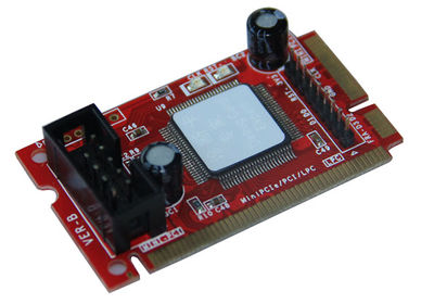
The Structure of 3-IN-1 INTERPOSER
- Mini-PCI interface to support notebook
- Mini-PCIe interface to support notebook
- LPC interface to support notebook
- LED indicators to show CLK and RESET signals
- ASIC to deal with Mini-PCI/Mini-PCIe/LPC signals
- Connector to connect this interposer to main-board
- Reserved for manufacture test only
The Mini PCI-E Interface in 3-IN-1 INTERPOSER
Mini-PCIe is used as a trend in the new notebook. Comparing to Mini-PCI, Mini-PCIe occupies less space. The 3-in-1 interposer uses below pins:PIN-8,PIN-10,PIN-12,PIN-14,PIN-16,PIN-17,and PIN-19, Those pins definition are optional in Mini-PCIe spec, and not all notebook vendors use those pin definition, so that not all notebooks can work with the Mini-PCIe interface.But our test shows more and more notebook manufacturers are beginning to use this, such as IBM, HP, Fujisu, Toshiba, Hasee, TCL, Acer and etc.. For the notebook, which don’t meet the above Mini-PCIe pin definition, this interface will not work and users need to use the other interface in this 3-in-1 interposer.
Note: Please be aware that Mini-PCIe is supported with limitation, and some notebooks will not work with interface
As reference, below is part of the notebook type of list, which can work with this mini-PCIe interface.
HP: V6000 series, including CT6…; V9000 series, including AT8, AT9…
IBM/Lenovo: CW3, CW4, LE4, LE5…
Hasee: 310, 320…
FujisuL: PORLAND 10 series
Acer: most of nee type
With more and more notebook manufacturers begin to support this Mini-PCIe debug card interface, just part of notebook part numbers are listed above, And users can expand their experience.
The Mini PCI Interface in 3-in-1 INTERPOSER
Mini PCI is a general interface, which is used in notebook. It includes 124 pins, This 3-in-1 interposer doesn’t fully use these pins, only 101 pins are used. This interface will work all notebooks, which are with Mini-PCI slot.
The LPC interface in 3-IN-1 INERPOSER
For the user, whose note book doesn’t support the Mini-PCI interface and the Mini-PCIe interface, Users can use the third port: LPC interface, LPC interface exists in all notebook main-boards. In this 3-in-1 interposer, from left to right, the LPC definition is:PIN1-LFRAME#, PIN2-LAD3, PIN3-LAD2, PIN4- LAD1, PIN5-LAD0, PIN6-GND, PIN7-LRESET#, PIN8-LCLK, PIN9-3.3V
Most of IBM/Lenovo Thinkpad series reserve the LPC interface in the motherboard.
For IBM X60 notebooks, the LPC interfaces are located in U39 slot of the mainboard. The Pin definitions are as below:
 A2->LRESET
 A3->LFRAME#
 A5->LCLK
 A9->LAD3
 A10->LAD2
 A11->LAD1
 A12->LAD0
But, usually, the notebook boards haven’t LPC connector or slots. And the users will need to connect this LPC port to the notebook by using wires. This requires that users have very good soldering sku. Below are some LPC interface chip pins definitions and users can connect the 3-in-1 interposer to the corresponding chip pins. For more information, please refer those chip datasheets.
Note: This Debug Card uses 3.3V as power supply, you can use any 3.3 and GND signals in your notebook main-board. Please be aware that connecting the 3-in-1 Interposer to a non-3.3V power may damage the Debug-Card.
If your notebooks use LPC VBIOS, you can also connect the 3-in-1 interposer’s LPC interface to your notebook’s BIOS pin as below. LPC BIOS Pin definition:
 PIN2-RST#
 PIN13-LAD0
 PIN14-LAD1
 PIN15-LAD2
 PIN16-GND
 PIN17-LAD3
 PIN23-LFRAME#
 PIN-VCC
 PIN31-CLK
DEBUG KING (3-in-1) Offline Use guide
When no 3-IN-1 INTERPOSER is connected to DEBUG KING HOST’s external port. Then users can read debug code English description by pushing buttons.
DEBUG KING (3-in-1) Online Use guide
Step1: Leaving Debug King’s USB port disconnected, And 3-IN-1 Interposer will power to DEBUG KING HOST. Connecting 3-IN-1 interposer to the notebook mother-board’s MiniPCI, MinPCIe or LPC port.
Step2: After turning on the power of tested notebook motherboard, DEBUG KING enters online working mode.
Step3: DEBUG KING begins to detect the test motherboard’s CLK signals. If it can’t find valid CLK signals, it will show information in the LCD screen. When Debug King fails to detected the CLK signals, please check the CLK LCD indication in 3-IN-1 INTERPOSER. If the CLK LED indicator in 3-IN-1 INTERPOSER doesn’t flicker, it means no CLK signals is outputted to 3-IN-1 INTERPOSER ,Usually, when using Mini-PCIe port and motherboard doesn’t support this Mini-PCIe port for debug, DEBUG KING will show this information, At this time, users need to try to use the other ports, such Mini-PCI or LPC.
Step4: When DEBUG KING captures the debug code successfully, it will show the corresponding English description or Photos. User can use the buttons to look at the close debug code description to get more repair information.


