Difference between revisions of "Real Time Clock RTC DS1307 Module"
(Created page with "==DESCRIPTION== The DS1307 Serial Real-Time Clock is a low-power, full binary-coded decimal (BCD) clock/calendar plus 56 bytes of NV SRAM. Address and data are transferred se...") |
(→How to buy it) |
||
| (22 intermediate revisions by the same user not shown) | |||
| Line 1: | Line 1: | ||
| − | == | + | ==Description== |
| + | [[File:DS1307.jpg]] | ||
| + | |||
The DS1307 Serial Real-Time Clock is a low-power, full binary-coded decimal (BCD) clock/calendar | The DS1307 Serial Real-Time Clock is a low-power, full binary-coded decimal (BCD) clock/calendar | ||
plus 56 bytes of NV SRAM. Address and data are transferred serially via a 2-wire, bi-directional bus. | plus 56 bytes of NV SRAM. Address and data are transferred serially via a 2-wire, bi-directional bus. | ||
| Line 8: | Line 10: | ||
battery supply. | battery supply. | ||
| − | == | + | ==Features== |
*Real-time clock (RTC) counts seconds,minutes, hours, date of the month, month, daof the week, and year with leap-year compensation valid up to 2100 | *Real-time clock (RTC) counts seconds,minutes, hours, date of the month, month, daof the week, and year with leap-year compensation valid up to 2100 | ||
*56-byte, battery-backed, nonvolatile (NV) RAM for data storage | *56-byte, battery-backed, nonvolatile (NV) RAM for data storage | ||
| Line 17: | Line 19: | ||
*Optional industrial temperature range:-40°C to +85°C | *Optional industrial temperature range:-40°C to +85°C | ||
*Available in 8-pin DIP or SOIC Underwriters Laboratory (UL) recognized | *Available in 8-pin DIP or SOIC Underwriters Laboratory (UL) recognized | ||
| + | |||
| + | ==Pin Description== | ||
| + | [[File:DS1307DIP.jpg]] | ||
| + | |||
| + | VCC - Primary Power Supply | ||
| + | |||
| + | GND - Ground | ||
| + | |||
| + | SDA - (Serial Data) | ||
| + | SDA is the input/output pin for the 2-wire serial interface. The SDA pin is open drain which requires an external pullup resistor. | ||
| + | |||
| + | SCL - (Serial Clock) | ||
| + | SCL is used to synchronize data movement on the serial interface. | ||
| + | |||
| + | SQW/OUT (Square Wave/Output Driver) – When enabled, the SQWE bit set to 1, the SQW/OUT pin | ||
| + | outputs one of four square wave frequencies (1Hz, 4kHz, 8kHz, 32kHz). The SQW/OUT pin is open | ||
| + | drain and requires an external pull-up resistor. SQW/OUT will operate with either Vcc or Vbat applied. | ||
| + | |||
| + | X1, X2 - 32.768kHz Crystal Connection | ||
| + | – Connections for a standard 32.768kHz quartz crystal. The internal oscillator circuitry is | ||
| + | designed for operation with a crystal having a specified load capacitance (CL) of 12.5pF. | ||
| + | |||
| + | ==Document== | ||
| + | [http://www.henningkarlsen.com/electronics/library.php?id=34 DS1307 Library 1] | ||
| + | |||
| + | [http://code.google.com/p/ds1307/downloads/list DS1307 Library 2] | ||
| + | |||
| + | [http://datasheets.maximintegrated.com/en/ds/DS1307.pdf DS1307 datasheet] | ||
| + | |||
| + | ==DS1307 Usage== | ||
| + | [[File:DS1307usage1.jpg]] | ||
| + | |||
| + | Download the [http://code.google.com/p/ds1307/downloads/list DS1307 Library] | ||
| + | then uncompress DS1307 Library into "libraries" folder of Arduino and restart ; | ||
| + | |||
| + | ==Testcode== | ||
| + | #include <WProgram.h> | ||
| + | #include <Wire.h> | ||
| + | #include <DS1307.h> written by mattt on the Arduino forum and modified by D. Sjunnesson | ||
| + | void setup() | ||
| + | { | ||
| + | Serial.begin(9600); | ||
| + | RTC.stop(); | ||
| + | RTC.set(DS1307_SEC,1); set the seconds | ||
| + | RTC.set(DS1307_MIN,23); set the minutes | ||
| + | RTC.set(DS1307_HR,12); set the hours | ||
| + | RTC.set(DS1307_DOW,4); set the day of the week | ||
| + | RTC.set(DS1307_DATE,15); set the date | ||
| + | RTC.set(DS1307_MTH,7); set the month | ||
| + | RTC.set(DS1307_YR,10); set the year | ||
| + | RTC.start(); | ||
| + | } | ||
| + | void loop() | ||
| + | { | ||
| + | Serial.print(RTC.get(DS1307_HR,true)); read the hour and also update all the values by pushing in true | ||
| + | Serial.print(":"); | ||
| + | Serial.print(RTC.get(DS1307_MIN,false));read minutes without update (false) | ||
| + | Serial.print(":"); | ||
| + | Serial.print(RTC.get(DS1307_SEC,false));read seconds | ||
| + | Serial.print(" "); some space for a more happy life | ||
| + | Serial.print(RTC.get(DS1307_DATE,false));read date | ||
| + | Serial.print("/"); | ||
| + | Serial.print(RTC.get(DS1307_MTH,false));read month | ||
| + | Serial.print("/"); | ||
| + | Serial.print(RTC.get(DS1307_YR,false)); //read year | ||
| + | Serial.println(); | ||
| + | delay(1000); | ||
| + | } | ||
| + | |||
| + | =How to buy = | ||
| + | Click here to buy [http://www.geeetech.com/real-time-clock-rtc-ds1307-modulearduino-compatible-p-440.html DS1307 module] | ||
Latest revision as of 10:42, 16 May 2014
Contents
Description
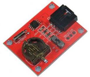
The DS1307 Serial Real-Time Clock is a low-power, full binary-coded decimal (BCD) clock/calendar plus 56 bytes of NV SRAM. Address and data are transferred serially via a 2-wire, bi-directional bus. The clock/calendar provides seconds, minutes, hours, day, date, month, and year information. The end of the month date is automatically adjusted for months with fewer than 31 days, including corrections for leap year. The clock operates in either the 24-hour or 12-hour format with AM/PM indicator. The DS1307 has a built-in power sense circuit that detects power failures and automatically switches to the battery supply.
Features
- Real-time clock (RTC) counts seconds,minutes, hours, date of the month, month, daof the week, and year with leap-year compensation valid up to 2100
- 56-byte, battery-backed, nonvolatile (NV) RAM for data storage
- Two-wire serial interface
- Programmable squarewave output signal
- Automatic power-fail detect and switch circuitry
- Consumes less than 500nA in battery backup mode with oscillator running
- Optional industrial temperature range:-40°C to +85°C
- Available in 8-pin DIP or SOIC Underwriters Laboratory (UL) recognized
Pin Description
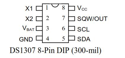
VCC - Primary Power Supply
GND - Ground
SDA - (Serial Data) SDA is the input/output pin for the 2-wire serial interface. The SDA pin is open drain which requires an external pullup resistor.
SCL - (Serial Clock) SCL is used to synchronize data movement on the serial interface.
SQW/OUT (Square Wave/Output Driver) – When enabled, the SQWE bit set to 1, the SQW/OUT pin outputs one of four square wave frequencies (1Hz, 4kHz, 8kHz, 32kHz). The SQW/OUT pin is open drain and requires an external pull-up resistor. SQW/OUT will operate with either Vcc or Vbat applied.
X1, X2 - 32.768kHz Crystal Connection – Connections for a standard 32.768kHz quartz crystal. The internal oscillator circuitry is designed for operation with a crystal having a specified load capacitance (CL) of 12.5pF.
Document
DS1307 Usage
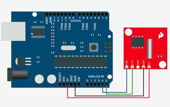
Download the DS1307 Library then uncompress DS1307 Library into "libraries" folder of Arduino and restart ;
Testcode
#include <WProgram.h>
#include <Wire.h>
#include <DS1307.h> written by mattt on the Arduino forum and modified by D. Sjunnesson
void setup()
{
Serial.begin(9600);
RTC.stop();
RTC.set(DS1307_SEC,1); set the seconds
RTC.set(DS1307_MIN,23); set the minutes
RTC.set(DS1307_HR,12); set the hours
RTC.set(DS1307_DOW,4); set the day of the week
RTC.set(DS1307_DATE,15); set the date
RTC.set(DS1307_MTH,7); set the month
RTC.set(DS1307_YR,10); set the year
RTC.start();
}
void loop()
{
Serial.print(RTC.get(DS1307_HR,true)); read the hour and also update all the values by pushing in true
Serial.print(":");
Serial.print(RTC.get(DS1307_MIN,false));read minutes without update (false)
Serial.print(":");
Serial.print(RTC.get(DS1307_SEC,false));read seconds
Serial.print(" "); some space for a more happy life
Serial.print(RTC.get(DS1307_DATE,false));read date
Serial.print("/");
Serial.print(RTC.get(DS1307_MTH,false));read month
Serial.print("/");
Serial.print(RTC.get(DS1307_YR,false)); //read year
Serial.println();
delay(1000);
}
How to buy
Click here to buy DS1307 module


