Difference between revisions of "Ramps1.4"
| Line 478: | Line 478: | ||
[[File:Sd.pdf]] | [[File:Sd.pdf]] | ||
| + | |||
| + | |||
| + | == How to buy == | ||
| + | Click here to buy: http://www.geeetech.com/ramps-14-reprap-mega-pololu-a4988-extend-shield-p-606.html | ||
Revision as of 03:31, 24 April 2014
Contents
Summary
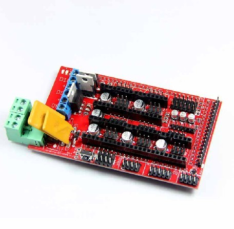
In RAMPS 1.4, the resistors and capacitors are now surface mount to fit more passive components. This does add another set of steps to assembly, but we stuck with larger sizes to make it fairly painless.
Features
- It has provisions for the cartesian robot and extruder.
- Expandable to control other accessories.
- 3 mosfets for heater / fan outputs and 3 thermistor circuits.
- Fused at 5A for additional safety and component protection
- Heated bed control with additional 11A fuse
- Fits 5 Pololu stepper driver board
- Pololu boards are on pin header sockets so they can be replaced easily or removed for use in future designs.
- I2C and SPI pins left available for future expansion.
- All the Mosfets are hooked into PWM pins for versatility.
- Servo style connectors are used to connect to the endstops, motors, and leds. These connectors are gold plated, rated for 3A, very compact, and globally available.
- USB type B receptacle
- SD Card add on available -- Available now made by Kliment - Sdramps
- LEDs indicate when heater outputs on
- Option to connect 2 motors to Z for Prusa Mendel
Safety Tip
even at just 12 volts - you have to take basic, common sense precautions to avoid fires. Just in case these fail, test your workshop smoke detector. Got no smoke detector? Get one!
Inspection
Stepper Driver Boards
- Jumpers need to be installed under each stepper driver:
 jumper   Yes/No  step size
 1     2    3
 no   no    no    full step
 yes  no    no    half step
 no   yes   no    1/4 step
 yes  yes   no    1/8 step
 yes  yes   yes   1/16 step
For now the default is 1/16 micro stepping (all jumpers installed under drivers)
- Cut the pin headers to 8 pins long so that they fit each side of the stepper driver.
- Insert the pin headers into the sockets on RAMPS
- Fit the stepper drivers onto the pin headers and solder. Only heat each pin for a few seconds at time to avoid damage to the socket.
Opto Endstops
- Cut the 26awg 3 conductor cable into 3 length.
- Note: you may want until you've built your machine to cut the cables to the perfect length.
- crimp and solder a female connector to the ends of each wire. (solder not necessary with proper crimp tools)
- use the 2.54mm 1x3 housing.
- Connect at least the minimum endstops.
| RAMPS End | |
| SIG (S) | |
| GND (-) | |
| VCC (+) |
| Endstop End | |
| VCC (+) | |
| SIG (S) | |
| GND (-) |
Mechanical Endstops
The recommended firmware will provide a configuration to use mechanical endstops with just two wires.
Find the area labelled "endstops" in the upper right corner of the board and for each of the X, Y, and Z pairs of pins (label should be below each set) do the following:
- Connect S (top row, labelled to the left) on RAMPS to NC on the switch.
- Connect GND on RAMPS to C on the switch.
Note: The latest firmware such as Marlin seems to use NO as the default pin on the switch. Otherwise you may need to invert the endstops in the firmware. You can use M119 to check your endstops status.
Put the connectors on the motor wires
- solder a female connector to the ends of each wire.
- use the 2.54mm 1x3 housing.
- Shown is the type used for servos in RC projects. See Stepper Motors for info on motors.
Thermistor Wires
Use a 2 pin 0.1" connector to terminate the thermistor wires.
- Connect the cable so the 2 wires go to T0
- Connect the 2 heater wires to D10 (E0H on older boards) and the + connection above it.
- If changing to an unverified firmware it is best to verify heater circuit function with a meter before connecting heater to prevent damage to the extruder.
Pololu carriage
This section assumes you are using Pololu, but there are other options. Insert two 1x8 pin headers into the board. If you bought a kit with one 16 pin header, simply cut it so that you have two 1x8. Make sure that the side with the labels has the long ends of the posts, and the side you want to solder is the side with the heat sink. Doing this backwards will cause you not to see the labels and will most likely not fit. Remember to apply a heat-sink to the largest chip on the back.
Final Setup
Pre-Flight Check
If you think you may have mistakes you can install only one stepper driver during initial testing and risk only one stepper driver.
The trimpot on the stepper drivers controls the current limit. Turn it all the way down (counter clock wise) and back up 25%. Be careful to not force the trimpot, it is delicate. You will need to fine tune the current limit later. Note that it is allways giving the motors that much power, even when not moving, so if your stepper motor drivers are getting hot, you may want to turn it down slightly.
Connect the minimum endstops for X,Y, and Z
Connect Motors (Do not disconnect or connect motors while powered; if the connection is loose, this will cause the motors to spazz and possibly kill your stepper driver.)
You may want to use this code to test all the electronics before installing any of the suggested firmwares.
Install firmware (More info below). Firmware flashing can be done without 12V power supply connected.
Wiring
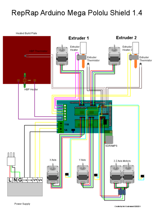
It is relatively simple to wire up the RAMPS. Just add the extruder heating coil wire to D10, the thermistor to the two T0 pins on middle right right, and wire up the steppers and endstops. From left to right, wire all of the stepper motor's wires as red, blue, green, and black or red, green, yellow, blue into the pins next to the Pololus. When you connect the wires to the endstops (if you are using 3 endstops, plug them into the MIN (-) slots), make sure you match the labels.
Note that tesla & tonok firmware use d9 and sprinter and johnny/tonok use d10 for the extruder hot end.
Warnings
Reversing +/- or otherwise incorrectly connecting power can destroy your electronics and cause fire hazard.
Incorrectly inserting stepper drivers will destroy your electronics and cause a fire risk. Always make sure power and USB is disconnected when removing or adjusting stepper drivers. Always make sure to insert drivers in correct orientation and in the socket correctly.
The endstop pins are Signal - GND - VCC, instead of the VCC - Sig - GND like the rest of RepRaps boards. Make sure to wire them correctly. This is done to allow squeezing fatter traces on the printable board.
Connecting Power
Connect your 12V power supply to the RAMPS shield. Reversing +/- or otherwise incorrectly connecting power can destroy your electronics and cause fire hazard.
The bottom pair of connectors marked 5A power the stepper drivers and Extruder heater/fan (D9, D10). The source should be rated a minimum of 5A.
The pair of connectors above marked 11A power a Heated Bed, or other output (D8). The source should be rated a minimum 11A (if both power rails are connected to the same supply it should have a minimum rating of 16A).
The barrel connector, on the Arduino MEGA, will NOT power RAMPS and will not provide power to the stepper motors, heated bed, etc.
The power connector plug may not be obviously labeled, looking at the power connection the positive is on the left and the negative is on the right of the plug.
Power Supply
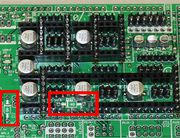
RAMPS is quite happy with the 12 V line from PCPowerSupply. Or you can hack up a 12V laptop power supply, or other 12 V "wall wart" power supply. Be sure that the power can output 5A or greater. Additional 11A may be needed for heated bed support. See Connecting power above. The 3 pins next to the reset switch are meant to optionally connect to your PSU. The PS_ON pin is intended to switch your power supply on and off. Many firmwares support pulling this pin low with M80 command to turn the power supply on, and M81 to turn it off. This behavior is desired for ATX power supplies and can be modified in firmware to support 5V high power supplies like those borrowed from an Xbox. Without D1 installed, or when the 12VIN is not connected, the Arduino gets its power from USB. If you want your kit powered without USB connected you need to solder in D1 OR connect VCC to your PSU. The VCC pin can be connected to your ATX's 5Vsb to continuously power the Arduino from your ATX power supply. You will want to make sure that D1 is not installed or cut out. The Arduino is not designed to be powered directly on the VCC rail and the VIN pin at the same time. The 5V pin in that connector on RAMPS only supplies the 5V to the auxiliary servo connectors. It is designed so that you can jumper it to the VCC pin and use the Arduino's power supply to supply 5V for extra servos if you are only powered from USB or 5V. Since there is not a lot of extra power from the Arduino's power supply you can connect it directly to your 5V power supply if you have one. You can also leave this pin not connected if you have no plan to add extra servos.
Maximum Input Voltage
Power Supply without diode
The 1N4004 diode connects the RAMPS input voltage to the MEGA. If your board does not have this diode soldered in, you can safely input as much as 35V. (The pololus can do up to 35V)
Power Supply with diode
If your board has a 1N4004 diode soldered in, do not apply more than 12 V to it. Original flavor Arduino Mega are rated to 12 V input. While Arduino Mega 2560 can take 20 V, it is not recommended.
Firmware and Pin Assignments
RAMPS 1.4 uses the same pin definitions as 1.3.
You will need the Arduino software at http://www.arduino.cc/en/Main/Software to upload the firmware to Arduino Mega. Arduino MEGA 2560 Rev3 requires Arduino software version 0023.
Sprinter and Marlin are popular and stable firmwares for RAMPS as of 3/28/2012. Pronterface is a cross platform printer control program that can be used for testing/printing.
Working preconfigured sprinter firmware can be downloaded at http://ultimachine.com/sites/default/files/UltiMachineRAMPS1-4Sprinter.zip . Mechanical is in the folder ending with ME, optical endstop firmware is in the folder ending in OE.
Working preconfigured Marlin firmware can be downloaded at http://www.mediafire.com/?un8s4i2lvdgd875 . is for mecanical endstops, for optical endstop need to reverse the logic of endstops from the configuration.h shell, the language of display is in italian, but can easy be canged from the shell language.h
Others (Need pins set in Firmware as below):
- mechanical endstops (now the default ultimachine.com option) require #define OPTO_PULLUPS_INTERNAL 1 to be added to configuration.h if not there by default.
Here are the pin definitions for this board.
// For RAMPS 1.4
#define X_STEP_PIN         54
#define X_DIR_PIN          55
#define X_ENABLE_PIN       38
#define X_MIN_PIN           3
#define X_MAX_PIN           2

#define Y_STEP_PIN         60
#define Y_DIR_PIN          61
#define Y_ENABLE_PIN       56
#define Y_MIN_PIN          14
#define Y_MAX_PIN          15

#define Z_STEP_PIN         46
#define Z_DIR_PIN          48
#define Z_ENABLE_PIN       62
#define Z_MIN_PIN          18
#define Z_MAX_PIN          19

#define E_STEP_PIN         26
#define E_DIR_PIN          28
#define E_ENABLE_PIN       24

#define SDPOWER            -1
#define SDSS               53
#define LED_PIN            13

#define FAN_PIN            9

#define PS_ON_PIN          12
#define KILL_PIN           -1

#define HEATER_0_PIN       10
#define HEATER_1_PIN       8
#define TEMP_0_PIN          13   // ANALOG NUMBERING
#define TEMP_1_PIN          14   // ANALOG NUMBERING
Bill of Materials
| ID | Description | Quantity | Part Number | Reichelt Order Number | Digikey Part Number (Description) |
|---|---|---|---|---|---|
| U1 | Arduino Mega | 1 | 2560 or 1280 | 1050-1018-ND(BOARD MCU MEGA2560) | |
| U2,U3,U4,U5 | Pololu stepper driver boards | 4 | A fifth one can be used for a 2nd extruder or extra axis | N/A | |
| C2 | 100nF capacitor (0805)(> highest planned voltage) | 1 | 311-1141-1-ND(CAP CER 0.1UF 25V 10% X7R 0805) | ||
| C1,C5,C8 | 10uF capacitor (153CLV-0405)(>5V) | 3 | 399-6724-1-ND(CAP ALUM 10UF 25V 20% SMD) | ||
| C3,C4,C6,C7,C9,C10 | 100uF capacitor (153CLV-0605)(> highest planned voltage) | 6 | 399-6726-1-ND(CAP ALUM 100UF 16V 20% SMD) | ||
| R1,R7,R11,R21,R22 | 4.7K resistor (0805)(1%) | 5 | RHM4.70KAECT-ND(RES 4.70K OHM .4W 1% 0805) | ||
| R2,R3,R4,R5,R6,R8,R9,R10 | 100K resistor (0805) | 8 | RHM100KAECT-ND(RES 100K OHM .4W 1% 0805) | ||
| R12 | 1K resistor (0805) | 1 | RHM1.00KAECT-ND(RES 1.00K OHM .4W 1% 0805) | ||
| R23,R24,R25 | 1.8K resistor (0805) | 3 | 311-1.80KCRCT-ND(RES 1.80K OHM 1/8W 1% 0805) | ||
| R16,R17,R18,R19,R20 | 10K resistor (0805) | 5 | P10.0KCCT-ND(RES 10.0K OHM 1/8W 1% 0805) | ||
| R13,R14,R15 | 10 ohm resistor (0805) | 3 | 541-10.0TCT-ND(RES 10.0 OHM .33W 1% 0805) | ||
| Q1,Q2,Q3 | N-channel Mosfet | 3 | STP55NF06L | ZXM 64N035 L3 | 497-6742-5-ND (MOSFET N-CH 60V 55A TO-220) |
| D1,D2 | Diode | 2 | 1N4004 | 1N 4004 | 1N4004FSCT-ND (DIODE GEN PURPOSE 400V 1A DO41) |
| F1 | PTC resettable fuse (30V, Hold5A, Trip10A) | 1 | MF-R500 | PFRA 500 | MF-R500-ND (FUSE PTC RESETTABLE 5A HOLD) |
| F2 | PTC resettable fuse (Hold11A) | 1 | MF-R1100 | RGEF1100-ND (POLYSWITCH RGE SERIES 11.0A HOLD) | |
| J2 | D8-D10 Outputs // 6 position screw terminal (min 11A per contact) OR Jack/Plug connector pair | 1 | 282837-6 | AKL 101-06 | WM7857-ND (CONN TERMINAL BLOCK 6POS 5.08MM) Alternative: 1x 609-4284-ND & 1x 609-4218-ND. May prevent overtemp events |
| LED1 | Green LED (0805) | 1 | L62505CT-ND(LED GREEN DIFF 0805 SMD) | ||
| LED2,LED3,LED4 | Red LED (0805) | 3 | L62501CT-ND(LED HI EFF RED DIFF 0805) | ||
| S1 | Push button switch | 1 | B3F-3100 | TASTER 3305B (should fit footprint also, but button will overhang board edge) | 450-1648-ND (SWITCH TACT RA H=6.35MM) |
| X1 | Power jack (Plug and fixed receptacle)(Min 11A per position more is better) | 1 | MSTBA 2,5 and MSTBT 2,5 (5.04mm spacing 4 connector) | WM7847-ND (CONN HEADER 4POS 5.08MM R/A TIN) & WM7953-ND (CONN TERM BLOCK 4POS 5.08MM R/A) | |
| 2 x 3 pin header | 8 | 961206-6404-AR | 3M9459-ND (CONN HEADER VERT DUAL 6POS GOLD) | ||
| 4 pin header | 5 | 961104-6404-AR | SL 1X36G 2,54 (3 of these) | 3M9449-ND (CONN HEADER VERT SGL 4POS GOLD) | |
| 6 pin header | 2 (? - from http://gala-automation.com/index.php/component/content/article/26-reprap-tutorials/42-ramps-14-bom) | 961106-6404-AR | 3M9451-ND (CONN HEADER VERT SGL 6POS GOLD) | ||
| 2 x 18 Pin Stackable Female Header (non stackables can be used with plated through holes) | 1 | MALE: SL 2X25G 2,54 (2 of them, shortened with a saw or pliers) | S7121-ND (CONN HEADER FMAL 36PS.1" DL GOLD) - Not Stackable | ||
| 8 Pin Stackable Female Header (non stackables can be used with plated through holes) | 5 | S7041-ND (CONN HEADER FEMALE 8POS .1" GOLD) - Not Stackable | |||
| 6 Pin Stackable Female Header (non stackables can be used with plated through holes) | 1 | S7039-ND (CONN HEADER FEMALE 6POS .1" GOLD) - Not Stackable | |||
| 24 Pin Female Header * Note * | 2 | Required to carry enough current for motors | S7057-ND (CONN HEADER FMALE 24POS .1" GOLD) - Rated @ 3A / Pin | ||
| 8 Pin Female Header * Note * | 4 | Required to carry enough current for motors | S7041-ND (CONN HEADER FEMALE 8POS .1" GOLD) - Rated @ 3A / Pin | ||
| 0.1" Jumpers | 15 | A26242-ND (SHUNT LP W/HANDLE 2 POS 30AU) | |||
| Circuit Board | 1 | v1.4 | N/A |
Note * You can use Female Headers which are not the exact size, but they are hard to break/cut so in this case buy some extra! (one wasted header per cut)
A BOM for sourcing the RAMPS components from Mouser is also available in this google spreadsheet (This list is incomplete and has missing or incorrect quantities.)
Shopping lists for v1.4 [1] .
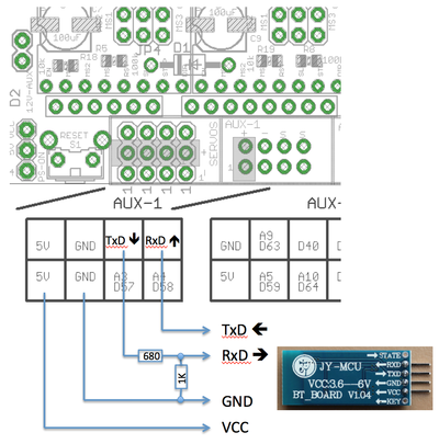
BT Extension
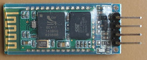
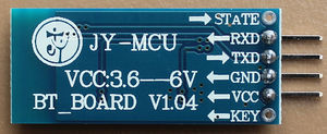
In order to get rid of the USB connection between RAMPS and the PC one may like to use Bluetooth. There is a cheap module available in the market called 'JY-MCU' (vendor Shenzhen Jiayuan Electronic Co.,Ltd.).
Change module setting
Before the module can be used the default setting has to be changed. Connect the module from PC via USB<->RS232 (RxD/TxD) interface with default settings (9600, N, 8, 1). The module shouldn't be paired at that moment. Apply with a terminal program the following AT commands:
AT OK
AT+BAUD8 OK115200BAUD (set baud rate for RAMPS/Arduino Mega)
AT+NAMEPRUSAI3 OKsetname (optional set name, default: linvor)
AT+PIN0000 OKsetPIN  (optional set pin, default: 1234)
More details about the configuration you will find here [[2]]
Wiring
On RAMPS/Arduino Mega the UART level are 5V but the BT module supports only 3.3V input. Therefore the TxD level has to be divided by resistor. This passive solution is fast enough for 115kBaud. Overall only 4 wires have to be soldered.
Connect via Bluetooth
Once you have setup your BT devices you can select from drop down list and control your RepRap as usual.
files
How to buy
Click here to buy: http://www.geeetech.com/ramps-14-reprap-mega-pololu-a4988-extend-shield-p-606.html
