Difference between revisions of "Asssembly"
From Geeetech Wiki
| Line 21: | Line 21: | ||
6. Try to attach the peeled end of the motor wire into the motor through hole pad. Start with white wire on round pad on M1 | 6. Try to attach the peeled end of the motor wire into the motor through hole pad. Start with white wire on round pad on M1 | ||
| − | [[File: | + | [[File:9.png|200px]] [[File:11.png|200px]] |
| − | + | [[File:12.png|200px]] | |
[[File:13.png|200px]][[File:14.png|200px]] | [[File:13.png|200px]][[File:14.png|200px]] | ||
[[File:15.png|200px]][[File:16.png|200px]][[File:17.png|200px]] | [[File:15.png|200px]][[File:16.png|200px]][[File:17.png|200px]] | ||
Revision as of 02:24, 14 November 2013
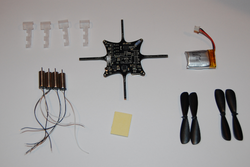
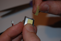
1. Check that you have everything that's needed
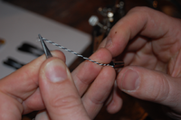
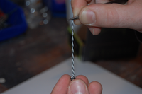
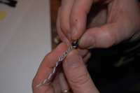
2. Twist the two motor wires together so they are easier to handle (and electromagnetic noise is reduced)
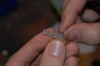
3. Thread the twisted motor wires through the motor mount arm section. It can be a bit tricky so have patience.
4. Insert the motor into the motor mount and be careful to not damage the motor wires while inserting it.
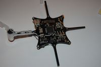
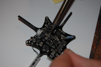
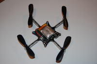
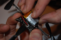
5. Press the motor mount on to the PCB arm. Be careful not to damage the wires when you do it. Start with M1.
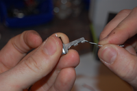
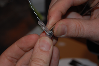
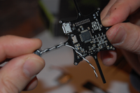
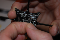
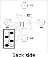
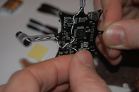
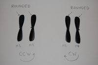
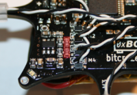
6. Try to attach the peeled end of the motor wire into the motor through hole pad. Start with white wire on round pad on M1
File:File.png
alt text
File:File.png
alt text
