Difference between revisions of "LilyPad Accelerometer ADXL335"
From Geeetech Wiki
(→Introduction) |
|||
| Line 1: | Line 1: | ||
==Introduction== | ==Introduction== | ||
[[File:IMG 0080.jpg]] | [[File:IMG 0080.jpg]] | ||
| + | [[File:IMG_0082.jpg]] | ||
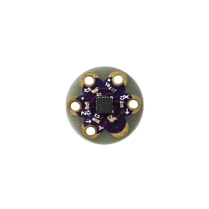
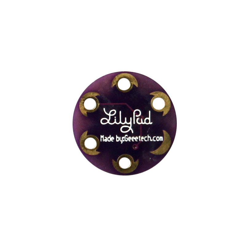
This is a three axis accelerometer for the LilyPad system. Based on the ADXL335 MEMS accelerometer from Analog Devices, the LilyPad Accelerometer can detect joint movement as well as inclination and vibration.The ADXL335 outputs a 0V to 3V analog signal on each of the X, Y, and Z axis. You will need to convert this analog voltage to a gravity amount and use trigonometry to calculate a true 'angle'. If you are not looking for tilt, it is very easy to use this sensor for basic motion sensing. | This is a three axis accelerometer for the LilyPad system. Based on the ADXL335 MEMS accelerometer from Analog Devices, the LilyPad Accelerometer can detect joint movement as well as inclination and vibration.The ADXL335 outputs a 0V to 3V analog signal on each of the X, Y, and Z axis. You will need to convert this analog voltage to a gravity amount and use trigonometry to calculate a true 'angle'. If you are not looking for tilt, it is very easy to use this sensor for basic motion sensing. | ||
Revision as of 01:30, 26 August 2013
Introduction
This is a three axis accelerometer for the LilyPad system. Based on the ADXL335 MEMS accelerometer from Analog Devices, the LilyPad Accelerometer can detect joint movement as well as inclination and vibration.The ADXL335 outputs a 0V to 3V analog signal on each of the X, Y, and Z axis. You will need to convert this analog voltage to a gravity amount and use trigonometry to calculate a true 'angle'. If you are not looking for tilt, it is very easy to use this sensor for basic motion sensing.
Features
- 3-axis sensing
- full-scale range of ±3 g
- Single-supply operation: 1.8 V to 3.6 V
- Excellent temperature stability
- Low power : 350 μA (typical)
- RoHS/WEEE lead-free compliant
- BW adjustment with a single capacitor per axis
Usage
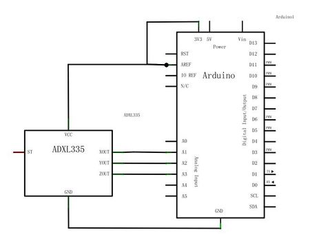
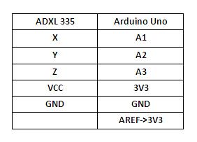
Here is the guide illustrates how to connect an Arduino to the ADXL335 breakout board. The following is a table describing which pins on the Arduino should be connected to the pins on the accelerometer:
Example code
// these constants describe the pins. They won't change:
const int xpin = A1;                  // x-axis of the accelerometer
const int ypin = A2;                  // y-axis
const int zpin = A3;                  // z-axis (only on 3-axis models)
//
int sampleDelay = 500;   //number of milliseconds between readings
void setup()
{
 // initialize the serial communications:
 Serial.begin(9600);
 //
 //Make sure the analog-to-digital converter takes its reference voltage from
 // the AREF pin
 pinMode(xpin, INPUT);
 pinMode(ypin, INPUT);
 pinMode(zpin, INPUT);
}
void loop()
{
 int x = analogRead(xpin);
 //
 //add a small delay between pin readings.  I read that you should
 //do this but haven't tested the importance
   delay(1);
 //
 int y = analogRead(ypin);
 //
 //add a small delay between pin readings.  I read that you should
 //do this but haven't tested the importance
   delay(1);
 //
 int z = analogRead(zpin);
 //
 //zero_G is the reading we expect from the sensor when it detects
 //no acceleration.  Subtract this value from the sensor reading to
 //get a shifted sensor reading.
 float zero_G =512;
 //
 //scale is the number of units we expect the sensor reading to
 //change when the acceleration along an axis changes by 1G.
 //Divide the shifted sensor reading by scale to get acceleration in Gs.
 float scale =102.3;
 //
 Serial.print(((float)x - zero_G)/scale);
 Serial.print("\t");
 //
 Serial.print(((float)y - zero_G)/scale);
 Serial.print("\t");
 //
 Serial.print(((float)z - zero_G)/scale);
 Serial.print("\n");
 //
 // delay before next reading:
 delay(sampleDelay);
}


