Difference between revisions of "Iduino DUE Mini"
| (22 intermediate revisions by the same user not shown) | |||
| Line 1: | Line 1: | ||
== Overview == | == Overview == | ||
| + | [[Image:DUE Mini 1.jpg]] | ||
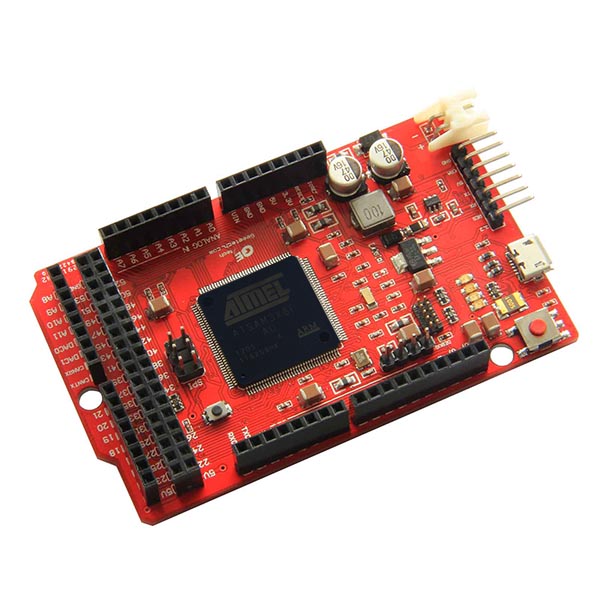
Iduino DUE Mini board derives from Arduino Due. It is completely compatible with Arduino Due. The microcontroller board also is based on | Iduino DUE Mini board derives from Arduino Due. It is completely compatible with Arduino Due. The microcontroller board also is based on | ||
| − | the[http://www.atmel.com/Images/doc11057.pdf Atmel SAM3X8E ARM Cortex-M3 CPU ] .It has 54 digital input/output pins (of which 12 can be used as PWM outputs), | + | the[http://www.atmel.com/Images/doc11057.pdf Atmel SAM3X8E ARM Cortex-M3 CPU ] .It has 54 digital input/output pins (of which 12 can be used as PWM outputs),12 analog inputs, |
| − | + | 4 UARTs (hardware serial ports), a 84 MHz clock, an USB OTG capable connection, 2 DAC (digital to analog), 2 TWI, a power jack,an SPI header, a JTAG header, | |
| − | + | a reset button and an erase button.Users could program it with Arduino IDE([http://arduino.cc/en/Main/Software Arduino v1.5.2 Beta:]). | |
| − | We made some changes on the original board,because if you got the Arduino DUE board, you will feel on it is: oh, so complicated! While | + | We made some changes on the original board,because if you got the Arduino DUE board, you will feel on it is: oh, so complicated! While you found you could |
| − | program it through both USB port. We think, why not remove one and leave users more chances to develope on another , it could make the board simple. | + | program it through both USB port. We think, why not remove one and leave users more chances to develope on another , it could make the board simple. As |
| − | + | ATmega16U2 circuit takes very much space on the board, we decide to remove it. And all the pins for external programmer are broken out. | |
| − | Of course ,it is more cost-efficient external programmer uses the ATmega16U2 as a USB-to-serial chip connected to the first UART of the SAM3X . | + | Of course ,it is more cost-efficient external programmer uses the [http://www.atmel.com/Images/doc7799.pdf ATmega16U2 ]as a USB-to-serial chip connected to the first UART of the SAM3X . |
| − | Similar with boards such as Arduino Mini or Arduino Pro, many board could share one external programmer.If you need 10 boards to build your projects, | + | Similar with boards such as Arduino Mini or Arduino Pro, many board could share one external programmer.If you need 10 boards to build your projects,you only need |
| − | + | one external programmer. That will save you much money. | |
| + | |||
| + | |||
| + | '''Warning: Unlike other Iduino boards, the Iduino Due Mini board runs at 3.3V. The maximum voltage that the I/O pins can tolerate is 3.3V. Providing higher voltages, like 5V to an I/O pin could damage the board. | ||
| + | ''' | ||
| + | |||
| + | '''Note: DUE Mini USB/Serial Adapter don't plug in the header to Iduino DUE Mini board when power on from the DC power jack .''' | ||
== About DUE Mini USB/Serial Adapter == | == About DUE Mini USB/Serial Adapter == | ||
| + | |||
| + | [[Image:DUE Mini USB1.jpg|500px]] | ||
| + | [[Image:DUE Mini USB2.jpg|500px]] | ||
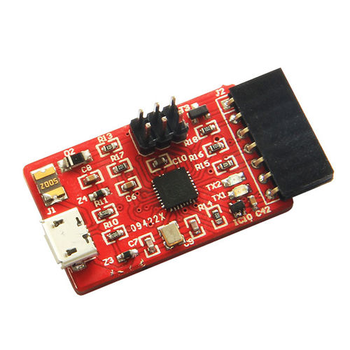
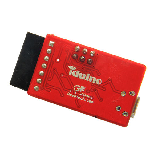
The DUE Mini USB/Serial Adapter is designed based on the ATmega16U2 circuit on Arduino DUE. With the bended female header, users could plug in the header to | The DUE Mini USB/Serial Adapter is designed based on the ATmega16U2 circuit on Arduino DUE. With the bended female header, users could plug in the header to | ||
Iduino DUE Mini board. | Iduino DUE Mini board. | ||
| + | |||
| + | |||
| + | |||
| + | == Features: == | ||
| + | |||
| + | |||
| + | *Microcontroller: AT91SAM3X8E | ||
| + | |||
| + | *Operating Voltage: 3.3V | ||
| + | |||
| + | *Recommended Input Voltage: 7-12V | ||
| + | |||
| + | *Min-Max Input Voltage: 6-15V | ||
| + | |||
| + | *Digital I/O Pins: 54 (of which 12 provide PWM output) | ||
| + | |||
| + | *Analog Input Pins: 12 | ||
| + | |||
| + | *Analog Outputs Pins: 2 | ||
| + | |||
| + | *Total DC Output Current on all I/O lines: 130 mA | ||
| + | |||
| + | *DC Current for 3.3V Pin: 800 mA | ||
| + | |||
| + | *DC Current for 5V Pin: 800 mA | ||
| + | |||
| + | *Flash Memory: 512 KB all available for the user applications | ||
| + | |||
| + | *SRAM: 96 KB (two banks: 64KB and 32KB) | ||
| + | |||
| + | *Clock Speed: 84 MHz | ||
| + | |||
| + | *Size:86.3×53.3mm | ||
| + | |||
| + | |||
| + | == USE == | ||
| + | |||
| + | '''1.Programming from USB on the board''' | ||
| + | |||
| + | To use this port, select "Arduino Due (Native USB Port)" as your board in the Arduino IDE. The USB(the one closest to the reset button) port is connected | ||
| + | |||
| + | directly to the SAM3X.Connect the USB port to your computer. | ||
| + | |||
| + | '''2.Programming from DUE Mini USB/Serial Adapter ''' | ||
| + | |||
| + | |||
| + | [[Image:DUE Mini 3.jpg]] | ||
| + | |||
| + | |||
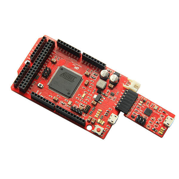
| + | To use this port, select "Arduino Due (Programming Port)" as your board in the Arduino IDE. DUE Mini USB/Serial Adapter plug in the header to | ||
| + | |||
| + | Iduino DUE Mini board,and connect to your computer. | ||
| + | |||
| + | |||
| + | == Documents: == | ||
| + | [http://arduino.cc/en/uploads/Main/arduino-Due-schematic.pdf Schematic:] | ||
| + | |||
| + | [http://arduino.cc/en/uploads/Main/arduino-Due-Reference-design.zip EAGLE files:] | ||
| + | |||
| + | [http://arduino.cc/en/Hacking/PinMappingSAM3X Pin Mapping:] | ||
| + | |||
| + | [http://arduino.cc/en/Main/Software Arduino v1.5 Beta:] | ||
| + | |||
| + | [http://arduino.cc/en/Main/ArduinoBoardDue Arduino Page:] | ||
Latest revision as of 05:46, 15 May 2013
Overview
Iduino DUE Mini board derives from Arduino Due. It is completely compatible with Arduino Due. The microcontroller board also is based on
theAtmel SAM3X8E ARM Cortex-M3 CPU .It has 54 digital input/output pins (of which 12 can be used as PWM outputs),12 analog inputs,
4 UARTs (hardware serial ports), a 84 MHz clock, an USB OTG capable connection, 2 DAC (digital to analog), 2 TWI, a power jack,an SPI header, a JTAG header,
a reset button and an erase button.Users could program it with Arduino IDE(Arduino v1.5.2 Beta:).
We made some changes on the original board,because if you got the Arduino DUE board, you will feel on it is: oh, so complicated! While you found you could
program it through both USB port. We think, why not remove one and leave users more chances to develope on another , it could make the board simple. As
ATmega16U2 circuit takes very much space on the board, we decide to remove it. And all the pins for external programmer are broken out.
Of course ,it is more cost-efficient external programmer uses the ATmega16U2 as a USB-to-serial chip connected to the first UART of the SAM3X .
Similar with boards such as Arduino Mini or Arduino Pro, many board could share one external programmer.If you need 10 boards to build your projects,you only need
one external programmer. That will save you much money.
Warning: Unlike other Iduino boards, the Iduino Due Mini board runs at 3.3V. The maximum voltage that the I/O pins can tolerate is 3.3V. Providing higher voltages, like 5V to an I/O pin could damage the board.
Note: DUE Mini USB/Serial Adapter don't plug in the header to Iduino DUE Mini board when power on from the DC power jack .
About DUE Mini USB/Serial Adapter
The DUE Mini USB/Serial Adapter is designed based on the ATmega16U2 circuit on Arduino DUE. With the bended female header, users could plug in the header to
Iduino DUE Mini board.
Features:
- Microcontroller: AT91SAM3X8E
- Operating Voltage: 3.3V
- Recommended Input Voltage: 7-12V
- Min-Max Input Voltage: 6-15V
- Digital I/O Pins: 54 (of which 12 provide PWM output)
- Analog Input Pins: 12
- Analog Outputs Pins: 2
- Total DC Output Current on all I/O lines: 130 mA
- DC Current for 3.3V Pin: 800 mA
- DC Current for 5V Pin: 800 mA
- Flash Memory: 512 KB all available for the user applications
- SRAM: 96 KB (two banks: 64KB and 32KB)
- Clock Speed: 84 MHz
- Size:86.3×53.3mm
USE
1.Programming from USB on the board
To use this port, select "Arduino Due (Native USB Port)" as your board in the Arduino IDE. The USB(the one closest to the reset button) port is connected
directly to the SAM3X.Connect the USB port to your computer.
2.Programming from DUE Mini USB/Serial Adapter
To use this port, select "Arduino Due (Programming Port)" as your board in the Arduino IDE. DUE Mini USB/Serial Adapter plug in the header to
Iduino DUE Mini board,and connect to your computer.


