Difference between revisions of "Opto-isolator Breakout"
(→introduction) |
|||
| Line 2: | Line 2: | ||
[[File:Opto-isolator Breakout09118.jpg|300px]] | [[File:Opto-isolator Breakout09118.jpg|300px]] | ||
| − | This is a board designed for opto-isolation. This board is helpful for connecting digital systems (like a 5V microcontroller) to a high-voltage or noisy system. | + | This is a board designed for opto-isolation. This board is helpful for connecting digital systems (like a 5V microcontroller) to a high-voltage or noisy system. This board electrically isolates a controller from the high-power system by use of an opto-isolator IC. This IC has two LEDs and two photodiodes built-in. This allows the low-voltage side to control a high voltage side. |
| − | + | We often use this board to allow a microcontroller control servos or other motors that use a higher voltage than the TTL logic on the (3.3V or 5V) micro, and may cause electromagnetic interferance with our system as the motors turn on and off. This board will isolate the systems, creating a type of electrical noise barrier between devices. | |
| + | |||
| + | This breakout board uses the ILD213T optoisolator and discrete transistors to correct the logic. Comes with two channels. Great for use in noisy circuits where signal lines require electrical isolation. | ||
| + | |||
| + | A normal LED opto-isolator will invert the logic of a signal. We threw some transistors on this compact board to correct the inversion. What you put into the IN pins, will be replicated on the the OUT pins, but at the higher voltage (HV). | ||
| − | |||
==Features== | ==Features== | ||
| Line 18: | Line 21: | ||
* Lead (Pb)-free component | * Lead (Pb)-free component | ||
* Component in accordance to RoHS 2002/95/EC andWEEE 2002/96/EC | * Component in accordance to RoHS 2002/95/EC andWEEE 2002/96/EC | ||
| + | |||
| + | ==Document== | ||
| + | [http://www.vishay.com/docs/83647/ild205t.pdf ild205t Datasheet] | ||
| + | |||
| + | ==How to buy== | ||
| + | Click here to buy [http://www.geeetech.com/d213-optoisolator-breakout-p-622.html Opto-isolator Breakout] | ||
Revision as of 02:38, 22 January 2013
Contents
[hide]introduction
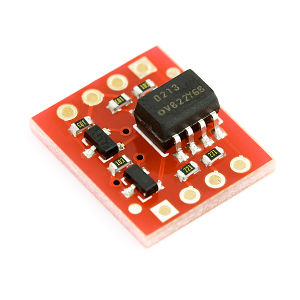
This is a board designed for opto-isolation. This board is helpful for connecting digital systems (like a 5V microcontroller) to a high-voltage or noisy system. This board electrically isolates a controller from the high-power system by use of an opto-isolator IC. This IC has two LEDs and two photodiodes built-in. This allows the low-voltage side to control a high voltage side.
We often use this board to allow a microcontroller control servos or other motors that use a higher voltage than the TTL logic on the (3.3V or 5V) micro, and may cause electromagnetic interferance with our system as the motors turn on and off. This board will isolate the systems, creating a type of electrical noise barrier between devices.
This breakout board uses the ILD213T optoisolator and discrete transistors to correct the logic. Comes with two channels. Great for use in noisy circuits where signal lines require electrical isolation.
A normal LED opto-isolator will invert the logic of a signal. We threw some transistors on this compact board to correct the inversion. What you put into the IN pins, will be replicated on the the OUT pins, but at the higher voltage (HV).
Features
- Two channel coupler
- SOIC-8 surface mountable package
- Standard lead spacing of 0.05"
- Available only on tape and reel option(conforms to EIA standard 481-2)
- Isolation test voltage, 4000 VRMS
- Compatible with dual wave, vapor phase andIR reflow soldering
- Lead (Pb)-free component
- Component in accordance to RoHS 2002/95/EC andWEEE 2002/96/EC
Document
How to buy
Click here to buy Opto-isolator Breakout
