Difference between revisions of "Arduino Bluetooth shield"
(→Hardware Diagram) |
|||
| Line 23: | Line 23: | ||
[[File:BT-1.jpg|500px]] | [[File:BT-1.jpg|500px]] | ||
| − | S1:Function button, This button is multi-function button include the function memory clearing (short press) which means deleting the address of the bluetooth module connected last time.Another function is to restore the default configuration(long press over 3s). | + | '''S1''':Function button, This button is multi-function button include the function memory clearing (short press) which means deleting the address of the bluetooth module connected last time.Another function is to restore the default configuration(long press over 3s). |
| − | S2: The switch S2 is for hardware/software selection for master or slave mode. When the switch S2 is toggled to "HW" side indicate that you can set the module to either master or slave mode by switch S3. When the switch S2 is toggled to "SW" side means the master/slave mode is only decided by AT command "AT+role0/1" | + | '''S2''': The switch S2 is for hardware/software selection for master or slave mode. When the switch S2 is toggled to "HW" side indicate that you can set the module to either master or slave mode by switch S3. When the switch S2 is toggled to "SW" side means the master/slave mode is only decided by AT command "AT+role0/1" |
| − | S3: The switch S3 is for master/slave selection only if the S2 is toggled to "HW" side. | + | '''S3''': The switch S3 is for master/slave selection only if the S2 is toggled to "HW" side. |
===Selectable UART connection=== | ===Selectable UART connection=== | ||
Revision as of 07:59, 4 January 2013
Contents
introduction
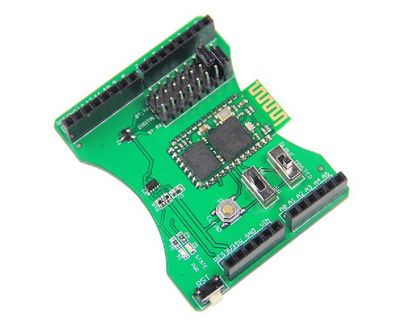
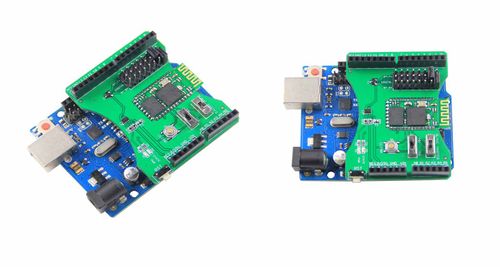
The Bluetooth Shield integrates a Serial Bluetooth module BLK-MD-BC04-B. It can be easily used with Arduino for transparent wireless serial connection setup. You can choose two pins from Arduino D0 to D7 as Software Serial Ports to communicate with Bluetooth Shield (D0 and D1 is Hardware Serial Port).
- Note
- The Shield may not be compatible with some Bluetooth capable devices, like Apple devices with special profile on Bluetooth function
Specifications:
- Arduino compatible
- Up to10m communication distance in house without obstacle
- UART interface (TTL) with programmable baud rate (SPP firmware installed)
- Bluetooth protocol: Bluetooth Specification v2.1 + EDR
- USB protocol: USB v1.1/2.0
- Frequency: 2.4GHz ISM band
- Modulation: GFSK (Gaussian Frequency
- Default Baud rate: 9600, Data bits: 8, Stop bit: 1, Parity: No parity
- A full set of configuration commands
- On board PCB Antenna
Hardware Specification
Hardware Diagram
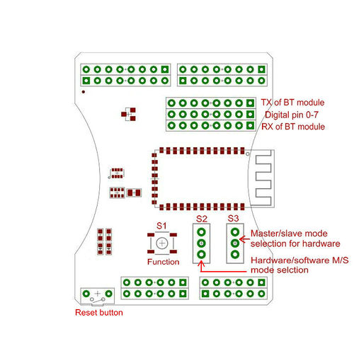
S1:Function button, This button is multi-function button include the function memory clearing (short press) which means deleting the address of the bluetooth module connected last time.Another function is to restore the default configuration(long press over 3s).
S2: The switch S2 is for hardware/software selection for master or slave mode. When the switch S2 is toggled to "HW" side indicate that you can set the module to either master or slave mode by switch S3. When the switch S2 is toggled to "SW" side means the master/slave mode is only decided by AT command "AT+role0/1"
S3: The switch S3 is for master/slave selection only if the S2 is toggled to "HW" side.
Selectable UART connection
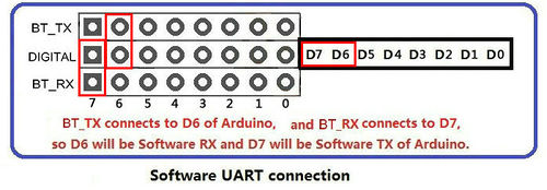
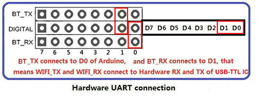
Users can use the jumpers to connect the BT_TX and BT_RX pins(5V) of Bluetooth shield to any Arduino.
Users must be aware that which Digital pin of Arduino connects to BT_TX needs to act as Arduino RX pin(Hardware/Software), and which connects to BT_RX needs to act as Arduino TX pin(Hardware/Software).
The following figure shows users how to use jumpers to configure UART communication between BT Shield and Arduino.
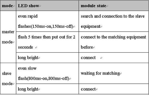
State Indication LED
Communication between two Bluetooth Shield
Hardware needed
- Arduino UNO processor x2
- Bluetooth Shield x2
Steps
1.Stack the Bluetooth shield to the Arduino Uno.
2.Program a simple code as blink without delay for your Arduino UNO first to avoid the serial communication conflict.
3.Set the jumpers to connect the BT_TX and BT_RX pins as the photo above to enable PC com port to send AT command to Bluetooth shield directly as the photo below
4.Open the com port of your Arduino UNO with the setting of baudrate 9600. and enter the "AT" to test the communication between BT shield and the USB port.
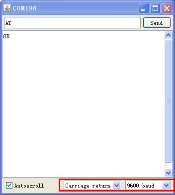
5.Set the switch "S1" on both shield to "HW" side, and set the switch "S2" to "SLAVE" on one shield and another to "MASTER" side.
6.The State LED always being on indicate that the two shield are connected.
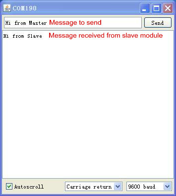
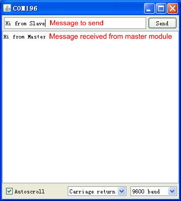
7.The connection is successful now, and you can type characters on the Serial monitor and send to each.
Document
How to buy
Click here to buy [Arduino Bluetooth shield]
