Difference between revisions of "Arduino WIFI shield"
(→Connect to the WiFi shield) |
(→Indicator LEDs) |
||
| (9 intermediate revisions by the same user not shown) | |||
| Line 48: | Line 48: | ||
There are four indicator LEDs(PWR, MODE, WIFI, LINK) on the Wifi Shield, users can know about the working phase of the shield based on the four indicator LEDs. Detailed information please refer to the following table: | There are four indicator LEDs(PWR, MODE, WIFI, LINK) on the Wifi Shield, users can know about the working phase of the shield based on the four indicator LEDs. Detailed information please refer to the following table: | ||
| − | [[File:Wifi-7.jpg| | + | [[File:Wifi-7.jpg|550px]] |
=== Antenna Interface === | === Antenna Interface === | ||
| Line 103: | Line 103: | ||
===Connect to the WiFi shield=== | ===Connect to the WiFi shield=== | ||
| − | On the other PC in the same network, we use Castalia Socket Tester as the TCP client and you can begin the data transmission | + | On the other PC in the same network, we use Castalia Socket Tester as the TCP client and you can begin the data transmission to wifi shield. |
| − | [[File:Wifi-6.jpg| | + | [[File:Wifi-6.jpg|500px]] |
[[File:Wifi-5.jpg|600px]] | [[File:Wifi-5.jpg|600px]] | ||
| + | |||
| + | ==Resources== | ||
| + | [http://www.geeetech.com/Documents/SOCKTEST.rar Castalia Socket Tester] | ||
| + | |||
| + | [http://www.wiznettechnology.com/include_Files/Just_Download.asp?PK_NUM=449&file_local_path=ReferenceFiles&file_local_name=WizFi210-User_Manual_EN_V1.12.pdf Wizfi210 User Manual] | ||
| + | |||
| + | [http://www.geeetech.com/Documents/WIZSmartScript.rar WIZSmartScript] | ||
| + | |||
| + | [http://www.geeetech.com/Documents/wifi%20shield%20schematic.pdf Wifi shield Schematic] | ||
==How to buy== | ==How to buy== | ||
| − | Click here to buy[Arduino wifi shield] | + | |
| + | Click here to buy [http://www.geeetech.com/wifiwizfi210-shield-for-iduinoarduino-p-617.html Arduino wifi shield] | ||
Latest revision as of 06:18, 26 December 2012
Contents
Introduction
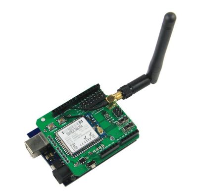
The Wifi Shield is based on Serial to Wi-Fi module Wizfi210 from Wiznet and compatible with Arduino and its clones. The Wifi Shield offers you a quick, easy, and effective way to add Wi-Fi capabilities to Arduino. The Wifi Shield allows you to achieve Wifi communication via UART by sending AT commands, which is an ideal solution for whom with limited or no Wi-Fi or RF expertise. The Shield supports data rates up to 11 Mbps, and is compliant with 802.11b.
Features
- Serial(UART) to Wifi.
- Simple AT commands for configuration and data communication.
- DHCP/Static IP, TCP/UDP, Server/Client, DNS.
- Operates with standard 802.11 b/g/n access points at speed up to 11 Mbps (802.11b).
- 802.11i Security (WEP, WPA, WPA2-PSK, Enterprise).
- High-throughput hardware AES and RC4 encryption/decryption engines.
- Limited AP Feature (Direct Connection to iPhone, iPad and Android-Phone without AP).
- Ultra low power consumption through dynamic power management.
Specifications
- Wifi Chip: WizFi210
- Radio Protocol: IEEE 802.11b/g/n Compatible
- Supported Data Rates: 11, 5.5, 2, 1 Mbps (IEEE 802.11b)
- Modulation: DSSS and CCK
- RF Operating Frequency: 2.4 - 2.497 GHz
- Antenna Options: Chip antenna and U.FL connector for external antenna
- Networking Protocols: UDP, TCP/IP (IPv4), DHCP, ARP, DNS, HTTP/HTTPS Client and Server(*)
- Power Consumption(Typical): Standby = 34.0 µA Receive = 125.0 mA Transmit = 135.0 mA
- RF Output Power (Typical): 8dBm ± 1dBm
- Security Protocols: WEP, WPA/WPA2–PSK, Enterprise, EAP-FAST, EAP-TLS, EAP-TTLS, PEAP
- I/O Interface: UART, SPI(*), I2C(*), WAKE, ALARM, GPIOs
- System Working Voltage: 3.3V
Hardware settings
Selectable UART connection
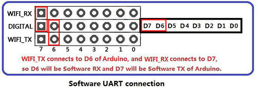
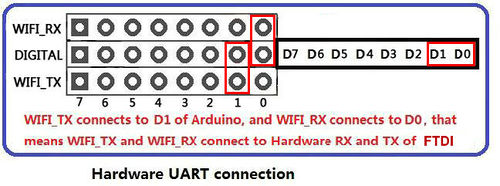
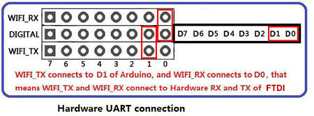
Users can use the jumpers to connect the WIFI_TX and WIFI_RX pins(5V) of Wifi Module to any Arduino.
Users must be aware that which Digital pin of Arduino connects to WIFI_TX needs to act as Arduino RX pin(Hardware/Software), and which connects to WIFI_RX needs to act as Arduino TX pin(Hardware/Software).
The following figure shows users how to use jumpers to configure UART communication between Wifi Shield and Arduino.
Indicator LEDs
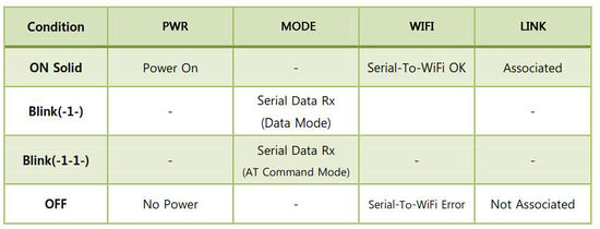
There are four indicator LEDs(PWR, MODE, WIFI, LINK) on the Wifi Shield, users can know about the working phase of the shield based on the four indicator LEDs. Detailed information please refer to the following table:
Antenna Interface
The shield comes with a 2.4G antenna; Make sure the antenna is assembled and antenna pad is buckled properly.
Buttons
There are three Buttons on the Shield. Reset, Function and Alarm1.
- Reset Button is used to reset the Arduino.
- Function Button is connected to GPIO21 of Wizfi210. If you click the Function Button twice consecutively, the WizFi210 is restored to factory default and changed <Limited AP mode>. And if you click the GPIO21(GPIO10) button three times consecutively, the WizFi210 is restored to factory default and will change to ad hoc mode to configure the WizFi210 via WiFi. (IP:192.168.1.254/Subnet:255.255.255.0/Gateway:192.168.1.1)
- Alarm1 Button is used to wake up wifi module from Standby Mode.
Switch
There is a Data/Command Mode Swtich(connected to GPIO29) on the shield. This switch only operate when user already set up the connection(TCP server/TCP client/UDP), which means module is data mode(can data communication). In this case, when you switch it to command mode, you can setting the module by using AT commands. When you switch it to data mode, you can data communication.
There is a Run/Program Mode Swtich(connected to UART1_RTS) on the shield. This switch allow user to pogram Wizfi210 chip
Wireless Communication between Wifi Shield and PC
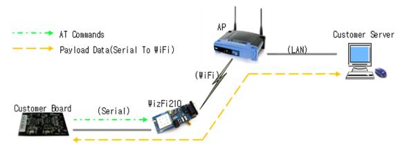
This photo demonstrate the working process of WIFI communication between PC and the custom board via wifi shield.
Hardware needed
- Arduino UNO processor x1
- WIFI shield x1
- WIFI Antenna x1
- Rounter x1
Preparation
- Stack the WIFI shield to the Arduino Uno and connect the antenna to the WIFI shield
- Program a simple code as blink without delay for your Arduino UNO first to avoid the serial communication conflict.
- Set the jumpers to connect the WIFI_TX and WIFI_RX pins as the photo above to enable PC com port to send AT command to WIFI shield directly as the photo below
- Set the "Run/Program" Switch to RUN side
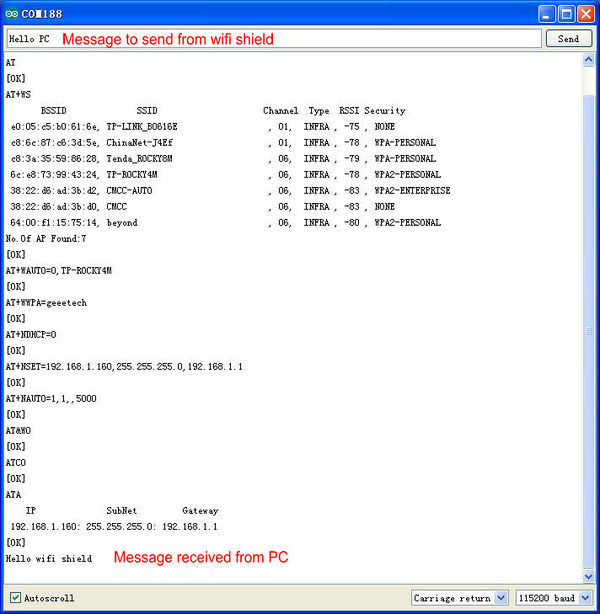
Configure the WIFI shield setting via Serial monitor
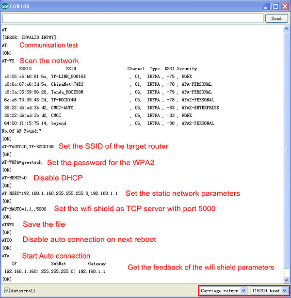
- Please set the baud rate to 115200 bps and Carriage return
- Open the com port of your Arduino UNO. And enter the "AT" to test the communication between WIFI shield and the USB port
- Enter "AT+WS" command to scan the network and get the list of found networks
- Enter "AT+WAUTO=0,Your SSID" to Set the SSID of the target router
- Enter "AT+WWPA=Your password" to set the password for the WPA2
- Enter "AT+NDHCP=0" to disable DHCP
- Enter "AT+NSET=192.168.1.150,255.255.255.0,192.168.1.1" to set the static network parameters
- Enter "AT+NAUTO=1,1,,5000 " to set the wifi shield as TCP server with port 5000
- Enter "AT&W0" to save the file
- Enter "ATC0" to disable auto connection on next reboot
- Enter "ATA" to start Auto connection
After getting the feedback from WiFi shield , we have finished creating a TCP server in the local network.And the indicator LEDs(marked "LINK" and "WIFI")will turn on to indicate the connection with the router.
Connect to the WiFi shield
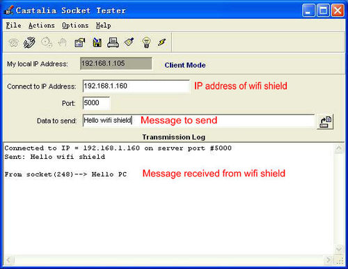
On the other PC in the same network, we use Castalia Socket Tester as the TCP client and you can begin the data transmission to wifi shield.
Resources
How to buy
Click here to buy Arduino wifi shield
