Difference between revisions of "ITG3205 Triple Axis Gyroscope Breakout"
(→Example code) |
(→Example code) |
||
| (7 intermediate revisions by the same user not shown) | |||
| Line 26: | Line 26: | ||
•Optional external clock inputs of 32.768kHz or 19.2MHz to synchronize with system clock<br> | •Optional external clock inputs of 32.768kHz or 19.2MHz to synchronize with system clock<br> | ||
•Pins broken out to a breadboard friendly 7-pin 0.1" pitch header<br> | •Pins broken out to a breadboard friendly 7-pin 0.1" pitch header<br> | ||
| + | |||
| + | ==Document== | ||
| + | [http://www.geeetech.com/Documents/ITG-3205-00-01.4.pdf ITG3205 Datasheet] | ||
== Pin Out and Signal Description == | == Pin Out and Signal Description == | ||
| Line 35: | Line 38: | ||
==Example code== | ==Example code== | ||
| + | For Arduino 1.0+ | ||
| + | //From http://www.varesano.net// | ||
#include <Wire.h> // I2C library, gyroscope | #include <Wire.h> // I2C library, gyroscope | ||
// Gyroscope ITG3200 | // Gyroscope ITG3200 | ||
| − | #define GYRO 0x68 // gyro address | + | #define GYRO 0x68 // when AD0 is connected to GND ,gyro address is 0x68. |
| + | //#define GYRO 0x69 when AD0 is connected to VCC ,gyro address is 0x69 | ||
#define G_SMPLRT_DIV 0x15 | #define G_SMPLRT_DIV 0x15 | ||
#define G_DLPF_FS 0x16 | #define G_DLPF_FS 0x16 | ||
| Line 55: | Line 61: | ||
* power management set to: | * power management set to: | ||
* clock select = internal oscillator | * clock select = internal oscillator | ||
| − | * | + | * no reset, no sleep mode |
| − | * | + | * no standby mode |
* sample rate to = 125Hz | * sample rate to = 125Hz | ||
* parameter to +/- 2000 degrees/sec | * parameter to +/- 2000 degrees/sec | ||
| Line 119: | Line 125: | ||
void writeTo(int DEVICE, byte address, byte val) { | void writeTo(int DEVICE, byte address, byte val) { | ||
Wire.beginTransmission(DEVICE); //start transmission to ACC | Wire.beginTransmission(DEVICE); //start transmission to ACC | ||
| − | Wire. | + | Wire.write(address); // send register address |
| − | Wire. | + | Wire.write(val); // send value to write |
Wire.endTransmission(); //end transmission | Wire.endTransmission(); //end transmission | ||
} | } | ||
| Line 126: | Line 132: | ||
void readFrom(int DEVICE, byte address, int num, byte buff[]) { | void readFrom(int DEVICE, byte address, int num, byte buff[]) { | ||
Wire.beginTransmission(DEVICE); //start transmission to ACC | Wire.beginTransmission(DEVICE); //start transmission to ACC | ||
| − | Wire. | + | Wire.write(address); //sends address to read from |
Wire.endTransmission(); //end transmission | Wire.endTransmission(); //end transmission | ||
| Line 135: | Line 141: | ||
while(Wire.available()) //ACC may send less than requested (abnormal) | while(Wire.available()) //ACC may send less than requested (abnormal) | ||
{ | { | ||
| − | buff[i] = Wire. | + | buff[i] = Wire.read(); // receive a byte |
i++; | i++; | ||
} | } | ||
Latest revision as of 07:42, 17 December 2012
Contents
Product Overview
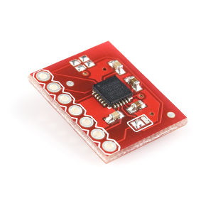
This is a breakout board for InvenSense's ITG-3205, a groundbreaking triple-axis, digital output gyroscope. The ITG-3205 features three 16-bit analog-to-digital converters (ADCs) for digitizing the gyro outputs, a user-selectable internal low-pass filter bandwidth, and a Fast-Mode I2C (400kHz) interface. Additional features include an embedded temperature sensor and a 2% accurate internal oscillator.
The ITG-3205 can be powered at anywhere between 2.1 and 3.6V. For power supply flexibility, the ITG-3205 has a separate VLOGIC reference pin (labeled VIO), in addition to its analog supply pin (VDD) which sets the logic levels of its serial interface. The VLOGIC voltage may be anywhere from 1.71V min to VDD max. For general use, VLOGIC can be tied to VCC. The normal operating current of the sensor is just 6.5mA.
Communication with the ITG-3205 is achieved over a two-wire (I2C) interface. The sensor also features a interrupt output, and an optional clock input. A jumper on the top of the board allows you to easily select the I2C address, by pulling the AD0 pin to either VCC or GND;If you don't plan on using the CLKIN pin, you can short the jumper on the bottom of the board to tie it to GND.
Applications
Motion-enabled game controllers
Motion-based portable gaming Motion-based
3D mice and 3D remote controls
“No Touch” UI
Health and sports monitoring
Features
•Digital-output X-, Y-, and Z-Axis angular rate sensors (gyros) on one integrated circuit
•Digitally-programmable low-pass filter
•Low 6.5mA operating current consumption for long battery life
•Wide VDD supply voltage range of 2.1V to 3.6V
•Standby current: 5μA
•Digital-output temperature sensor
•Fast Mode I2C (400kHz) serial interface
•Optional external clock inputs of 32.768kHz or 19.2MHz to synchronize with system clock
•Pins broken out to a breadboard friendly 7-pin 0.1" pitch header
Document
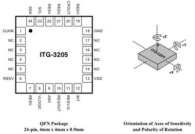
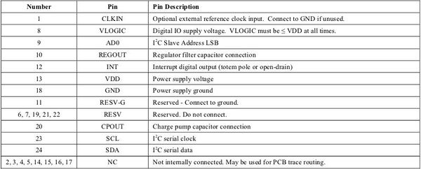
Pin Out and Signal Description
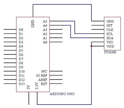
Wiring Diagram
Example code
For Arduino 1.0+
//From http://www.varesano.net//
#include <Wire.h> // I2C library, gyroscope
// Gyroscope ITG3200
#define GYRO 0x68 //  when AD0 is connected to GND ,gyro address is 0x68.
//#define GYRO 0x69   when AD0 is connected to VCC ,gyro address is 0x69
#define G_SMPLRT_DIV 0x15
#define G_DLPF_FS 0x16
#define G_INT_CFG 0x17
#define G_PWR_MGM 0x3E
#define G_TO_READ 8 // 2 bytes for each axis x, y, z
// offsets are chip specific.
int g_offx = 120;
int g_offy = 20;
int g_offz = 93;
int hx, hy, hz, turetemp;
//initializes the gyroscope
void initGyro()
{
 /*****************************************
 * ITG 3200
 * power management set to:
 * clock select = internal oscillator
 * no reset, no sleep mode
 * no standby mode
 * sample rate to = 125Hz
 * parameter to +/- 2000 degrees/sec
 * low pass filter = 5Hz
 * no interrupt
 ******************************************/
 writeTo(GYRO, G_PWR_MGM, 0x00);
 writeTo(GYRO, G_SMPLRT_DIV, 0x07); // EB, 50, 80, 7F, DE, 23, 20, FF
 writeTo(GYRO, G_DLPF_FS, 0x1E); // +/- 2000 dgrs/sec, 1KHz, 1E, 19
 writeTo(GYRO, G_INT_CFG, 0x00);
}
void getGyroscopeData(int * result)
{
 /**************************************
 Gyro ITG-3200 I2C
 registers:
 temp MSB = 1B, temp LSB = 1C
 x axis MSB = 1D, x axis LSB = 1E
 y axis MSB = 1F, y axis LSB = 20
 z axis MSB = 21, z axis LSB = 22
 *************************************/
 int regAddress = 0x1B;
 int temp, x, y, z;
 byte buff[G_TO_READ];
 readFrom(GYRO, regAddress, G_TO_READ, buff); //read the gyro data from the ITG3200
 result[0] = ((buff[2] << 8) | buff[3]) + g_offx;
 result[1] = ((buff[4] << 8) | buff[5]) + g_offy;
 result[2] = ((buff[6] << 8) | buff[7]) + g_offz;
 result[3] = (buff[0] << 8) | buff[1]; // temperature
 }
 //
void setup()
{
 Serial.begin(9600);
 Wire.begin();
 initGyro();
}
//
void loop()
{
 byte addr;
 int gyro[4];
 getGyroscopeData(gyro);
 hx = gyro[0] / 14.375;
 hy = gyro[1] / 14.375;
 hz = gyro[2] / 14.375;
 turetemp = 35+ ((double) (gyro[3] + 13200)) / 280; // temperature
 Serial.print(" X=");
 Serial.print(hx);
 Serial.print(" Y=");
 Serial.print(hy);
 Serial.print(" Z=");
 Serial.print(hz);
 Serial.print(" F=");
 Serial.print(turetemp);
 Serial.print((char)223);
 Serial.println("C");
 delay(50);
}
//---------------- Functions
//Writes val to address register on ACC
void writeTo(int DEVICE, byte address, byte val) {
  Wire.beginTransmission(DEVICE); //start transmission to ACC
  Wire.write(address);        // send register address
  Wire.write(val);        // send value to write
  Wire.endTransmission(); //end transmission
}
//reads num bytes starting from address register on ACC in to buff array
 void readFrom(int DEVICE, byte address, int num, byte buff[]) {
 Wire.beginTransmission(DEVICE); //start transmission to ACC
 Wire.write(address);        //sends address to read from
 Wire.endTransmission(); //end transmission

 Wire.beginTransmission(DEVICE); //start transmission to ACC
 Wire.requestFrom(DEVICE, num);    // request 6 bytes from ACC

 int i = 0;
 while(Wire.available())    //ACC may send less than requested (abnormal)
 {
   buff[i] = Wire.read(); // receive a byte
   i++;
 }
 Wire.endTransmission(); //end transmission
}
How to buy
Click here to buy Triple axis gyroscope breakout


