Difference between revisions of "BMA180 Triple Axis Accelerometer Breakout"
(→Example code) |
|||
| (6 intermediate revisions by the same user not shown) | |||
| Line 1: | Line 1: | ||
==Introduction== | ==Introduction== | ||
| − | [[File:BMA180.jpg]] | + | [[File:BMA180.jpg|300px]] |
This is a breakout board for BOSCH BMA180 digital triple axis accelerometer.BMA180 is a digital ultra-high-performance tri-axial low-g acceleration sensor for consumer | This is a breakout board for BOSCH BMA180 digital triple axis accelerometer.BMA180 is a digital ultra-high-performance tri-axial low-g acceleration sensor for consumer | ||
| Line 57: | Line 57: | ||
[[File:BMA table.jpg]] | [[File:BMA table.jpg]] | ||
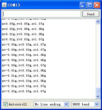
| + | After uploading the sketch, in the serial monitor of the Arduino IDE, we can read the 3 axis data when it is placed vertically. | ||
| + | |||
| + | [[File:BMA180 COM.jpg]] | ||
==Example code== | ==Example code== | ||
| + | For Arduino 1.0+ | ||
| + | |||
//BMA180 triple axis accelerometer sample code// | //BMA180 triple axis accelerometer sample code// | ||
//www.geeetech.com// | //www.geeetech.com// | ||
| + | // | ||
#include <Wire.h> | #include <Wire.h> | ||
| − | #define | + | #define BMA180 0x40 //address of the accelerometer |
#define RESET 0x10 | #define RESET 0x10 | ||
#define PWR 0x0D | #define PWR 0x0D | ||
| Line 88: | Line 94: | ||
byte temp1; | byte temp1; | ||
// | // | ||
| − | writeTo( | + | writeTo(BMA180,RESET,0xB6); |
//wake up mode | //wake up mode | ||
| − | writeTo( | + | writeTo(BMA180,PWR,0x10); |
// low pass filter, | // low pass filter, | ||
| − | readFrom( | + | readFrom(BMA180, BW,1,temp); |
temp1=temp[0]&0x0F; | temp1=temp[0]&0x0F; | ||
| − | writeTo( | + | writeTo(BMA180, BW, temp1); |
// range +/- 2g | // range +/- 2g | ||
| − | readFrom( | + | readFrom(BMA180, RANGE, 1 ,temp); |
temp1=(temp[0]&0xF1) | 0x04; | temp1=(temp[0]&0xF1) | 0x04; | ||
| − | writeTo( | + | writeTo(BMA180,RANGE,temp1); |
} | } | ||
// | // | ||
| Line 107: | Line 113: | ||
int n=6; | int n=6; | ||
byte result[5]; | byte result[5]; | ||
| − | readFrom( | + | readFrom(BMA180, DATA, n , result); |
int x= (( result[0] | result[1]<<8)>>2)+offx ; | int x= (( result[0] | result[1]<<8)>>2)+offx ; | ||
| Line 139: | Line 145: | ||
{ | { | ||
Wire.beginTransmission(DEVICE); //start transmission to ACC | Wire.beginTransmission(DEVICE); //start transmission to ACC | ||
| − | Wire. | + | Wire.write(address); //send register address |
| − | Wire. | + | Wire.write(val); //send value to write |
Wire.endTransmission(); //end trnsmisson | Wire.endTransmission(); //end trnsmisson | ||
} | } | ||
| Line 147: | Line 153: | ||
{ | { | ||
Wire.beginTransmission(DEVICE); //start transmission to ACC | Wire.beginTransmission(DEVICE); //start transmission to ACC | ||
| − | Wire. | + | Wire.write(address); //send reguster address |
Wire.endTransmission(); //end transmission | Wire.endTransmission(); //end transmission | ||
| Line 156: | Line 162: | ||
while(Wire.available()) //ACC may abnormal | while(Wire.available()) //ACC may abnormal | ||
{ | { | ||
| − | buff[i] =Wire. | + | buff[i] =Wire.read(); //receive a byte |
i++; | i++; | ||
} | } | ||
Wire.endTransmission(); //end transmission | Wire.endTransmission(); //end transmission | ||
} | } | ||
| + | |||
==Document== | ==Document== | ||
[http://www.geeetech.com/Documents/BST-BMA180-DS000.pdf BMA180 Triple Axis Accelerometer datasheet] | [http://www.geeetech.com/Documents/BST-BMA180-DS000.pdf BMA180 Triple Axis Accelerometer datasheet] | ||
Latest revision as of 01:55, 10 December 2012
Introduction
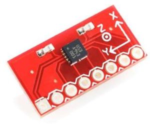
This is a breakout board for BOSCH BMA180 digital triple axis accelerometer.BMA180 is a digital ultra-high-performance tri-axial low-g acceleration sensor for consumer market applications. It allows measurements of static as well as dynamic accelerations with very high accuracy. Due to its three perpendicular axes it gives the absolute orientation in a gravity field. As all other Bosch inertial sensors, it is a two-chip arrangement (here in a plastic package). An ASIC evaluates the output of a three-channel micromechanical acceleration- sensing element that works according to the differential capacitance principle. The underlying micromachining process has proven its capability in much more than 100 million Bosch accelerometers and gyroscopes so far.
The BMA180 provides a digital full 14 bit output signal via a 4-wire SPI or I2C interface. With an appropriate command the full measurement range can be chosen between 1 g and 16 g. A second-order Butterworth filter with switch-able pole-frequencies between 10 Hz and 600 Hz is included to provide pre-conditioning of the measured acceleration signal. Typical noise level and quantization lead – in 2 g-mode - to a resolution of typically 0.5 mg and a typical accuracy of below 0,25° in an inclination sensing application, respectively. The current consumption is typically 650 μA at a supply voltage of 2.4 V in standard mode. Furthermore, the sensor can be switched into a very low-power mode where it informs the host system about an acceleration change via an interrupt pin. This feature can be used to wake-up the host system from a sleep mode.
The sensor also features self-test capability. It is activated via SPI/I2C command, which results
in a physical deflection of the seismic mass in the sensing element due to an electrostatic force.
Thus, it provides full testing of the complete signal evaluation path including the micro-machined
sensor structure and the evaluation ASIC.
Features
- Wide variety of measurment ranges (±1g, 1.5g, 2g, 3g, 4g, 8g and 16g)
- 14- or 12-bit ADC conversion
- 2 selectable I2C addresses
- Programmable integrated digital filters (no external components necessary)
- 8 low-pass filters
- 1 high-pass filter
- 1 band-pass filter
- Programmable interrupt features:
- Wake-up
- Low-g detection
- High-g detection
- Tap sensing
- Slope detection
- 2 main standard modes: low-noise and low-power
- Sleep mode
- Wake-up mode
- Self-test capability
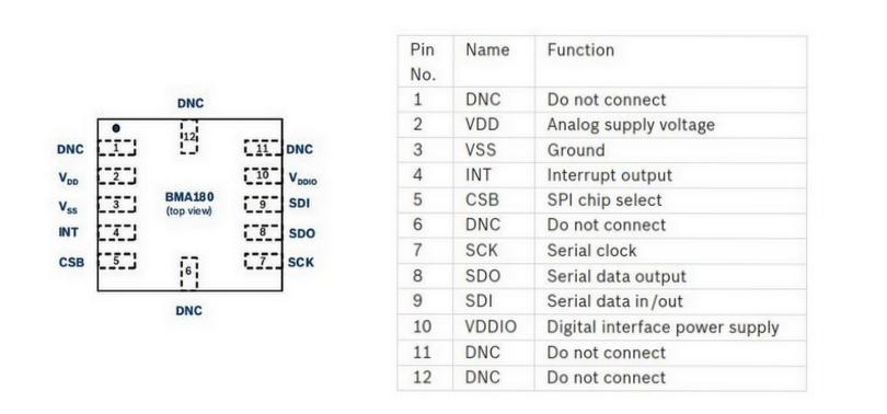
Pin description
Usage
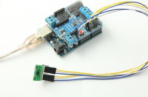
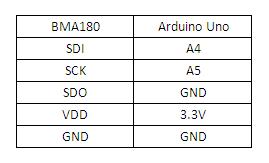
Here is the guide illustrates how to connect an Arduino to the BMA180 breakout board. The following is a table describing which pins on the Arduino should be connected to the pins on the accelerometer:
After uploading the sketch, in the serial monitor of the Arduino IDE, we can read the 3 axis data when it is placed vertically.
Example code
For Arduino 1.0+
//BMA180 triple axis accelerometer sample code//
//www.geeetech.com//
//
#include <Wire.h>
#define BMA180 0x40  //address of the accelerometer
#define RESET 0x10
#define PWR 0x0D
#define BW 0X20
#define RANGE 0X35
#define DATA 0x02
//
int offx = 31;
int offy = 47;
int offz = -23;
//
void setup()
{
 Serial.begin(9600);
 Wire.begin();
 Serial.println("Demo started, initializing sensors");
 AccelerometerInit();
 Serial.println("Sensors have been initialized");
}
//
void AccelerometerInit()
//
{
 byte temp[1];
 byte temp1;
  //
  writeTo(BMA180,RESET,0xB6);
  //wake up mode
  writeTo(BMA180,PWR,0x10);
  // low pass filter,
  readFrom(BMA180, BW,1,temp);
  temp1=temp[0]&0x0F;
  writeTo(BMA180, BW, temp1);
  // range +/- 2g
  readFrom(BMA180, RANGE, 1 ,temp);
  temp1=(temp[0]&0xF1) | 0x04;
  writeTo(BMA180,RANGE,temp1);
}
//
void AccelerometerRead()
{
 // read in the 3 axis data, each one is 14 bits
 // print the data to terminal
 int n=6;
 byte result[5];
 readFrom(BMA180, DATA, n , result);

 int x= (( result[0] | result[1]<<8)>>2)+offx ;
 float x1=x/4096.0;
 Serial.print("x=");
 Serial.print(x1);
 Serial.print("g");
 //
 int y= (( result[2] | result[3]<<8 )>>2)+offy;
 float y1=y/4096.0;
 Serial.print(",y=");
 Serial.print(y1);
 Serial.print("g");
 //
 int z= (( result[4] | result[5]<<8 )>>2)+offz;
 float z1=z/4096.0;
 Serial.print(",z=");
 Serial.print(z1);
 Serial.println("g");
}
//
void loop()
{
 AccelerometerRead();
 delay(300); // slow down output
}
//
//---------------- Functions--------------------
//Writes val to address register on ACC
void writeTo(int DEVICE, byte address, byte val)
{
  Wire.beginTransmission(DEVICE);   //start transmission to ACC
  Wire.write(address);               //send register address
  Wire.write(val);                   //send value to write
  Wire.endTransmission();           //end trnsmisson
}
//reads num bytes starting from address register in to buff array
 void readFrom(int DEVICE, byte address , int num ,byte buff[])
 {
 Wire.beginTransmission(DEVICE); //start transmission to ACC
 Wire.write(address);            //send reguster address
 Wire.endTransmission();        //end transmission

 Wire.beginTransmission(DEVICE); //start transmission to ACC
 Wire.requestFrom(DEVICE,num);  //request 6 bits from ACC

 int i=0;
 while(Wire.available())        //ACC may abnormal
 {
 buff[i] =Wire.read();        //receive a byte
 i++;
 }
 Wire.endTransmission();         //end transmission
 }
Document
BMA180 Triple Axis Accelerometer datasheet
How to buy
Click here to buy BMA180 digital triple axis accelerometer
