Difference between revisions of "DS3234 Real-Time Clock Module"
| Line 68: | Line 68: | ||
After uploading the sketch, in the serial monitor of the Arduino IDE, we can read the real time. | After uploading the sketch, in the serial monitor of the Arduino IDE, we can read the real time. | ||
| − | [[File:DS3234 com.jpg| | + | [[File:DS3234 com.jpg|300px]] |
==Example code== | ==Example code== | ||
| − | + | ||
| − | + | [DS3234 Real-Time Clock example] | |
| − | |||
| − | |||
| − | |||
| − | |||
| − | |||
| − | |||
| − | |||
| − | |||
| − | |||
| − | |||
| − | |||
| − | |||
| − | |||
| − | |||
| − | |||
| − | |||
| − | |||
| − | |||
| − | |||
| − | |||
| − | |||
| − | |||
| − | |||
| − | |||
| − | |||
| − | |||
| − | |||
| − | |||
| − | |||
| − | |||
| − | |||
| − | |||
| − | |||
| − | |||
| − | |||
| − | |||
| − | |||
| − | |||
| − | |||
| − | |||
| − | |||
| − | |||
| − | |||
| − | |||
| − | |||
| − | |||
| − | |||
| − | |||
| − | |||
| − | |||
| − | |||
| − | |||
| − | |||
| − | |||
| − | |||
| − | |||
| − | |||
| − | |||
| − | |||
| − | |||
| − | |||
| − | |||
| − | |||
| − | |||
| − | |||
| − | |||
| − | |||
| − | |||
| − | |||
| − | |||
| − | |||
| − | |||
| − | |||
| − | |||
| − | |||
| − | |||
| − | |||
| − | |||
| − | |||
| − | |||
| − | |||
| − | |||
| − | |||
| − | |||
| − | |||
| − | |||
| − | |||
| − | |||
| − | |||
| − | |||
| − | |||
| − | |||
| − | |||
| − | |||
| − | |||
==Document== | ==Document== | ||
| + | [DS3234 Real-Time datasheet] | ||
==How to buy== | ==How to buy== | ||
| + | Click here to buy [DS3234 Real-Time Clock Module] | ||
Revision as of 02:36, 9 June 2012
Introduction
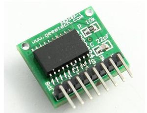
This is a breakout board for MAXIM DS3234 real-time clock.The DS3234 is a low-cost, extremely accurate SPI™ bus real-time clock (RTC) with an integrated temperature-com- pensated crystal oscillator (TCXO) and crystal. The DS3234 incorporates a precision, temperature-compen- sated voltage reference and comparator circuit to monitor VCC. When VCC drops below the power-fail voltage (VPF), the device asserts the RST output and also disables read and write access to the part when VCC drops below both VPF and VBAT. The RST pin is monitored as a pushbutton input for generating a µP reset. The device switches to the backup supply input and maintains accurate timekeeping when main power to the device is interrupted. The integra- tion of the crystal resonator enhances the long-term accu- racy of the device as well as reduces the piece-part count in a manufacturing line. The DS3234 is available in com- mercial and industrial temperature ranges, and is offered in an industry-standard 300-mil, 20-pin SO package.
The DS3234 also integrates 256 bytes of battery-backed SRAM. In the event of main power loss, the contents of the memory are maintained by the power source con- nected to the VBAT pin. The RTC maintains seconds, minutes, hours, day, date, month, and year information. The date at the end of the month is automatically adjust- ed for months with fewer than 31 days, including correc- tions for leap year. The clock operates in either the 24-hour or 12-hour format with AM/PM indicator. Two programmable time-of-day alarms and a programmable square-wave output are provided. Address and data are transferred serially by an SPI bidirectional bus.
Features
- Accuracy ±2ppm from 0°C to +40°C
- Accuracy ±3.5ppm from -40°C to +85°C
- Battery Backup Input for Continuous Timekeeping
- Operating Temperature Ranges
- Commercial: 0°C to +70°C
- Industrial: -40°C to +85°C
- Low-Power Consumption
- Real-Time Clock Counts Seconds, Minutes,
- Hours, Day, Date, Month, and Year with Leap Year
- Compensation Valid Up to 2099
- Two Time-of-Day Alarms
- Programmable Square-Wave Output
- 4MHz SPI Bus Supports Modes 1 and 3
- Digital Temp Sensor Output: ±3°C Accuracy
- Register for Aging Trim
- RST Input/Output
- 300-Mil, 20-Pin SO Package
- Underwriters Laboratories Recognized
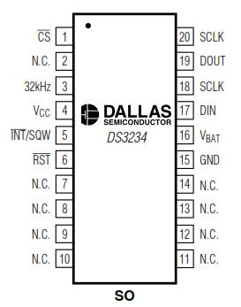
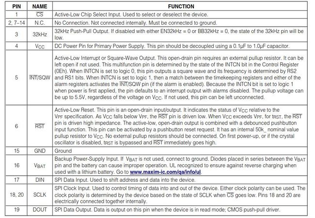
Pin definition
Usage
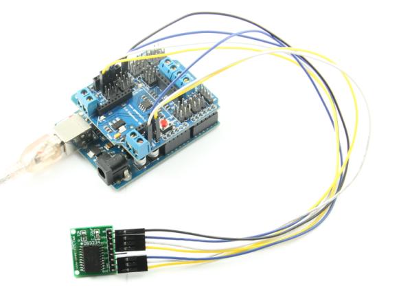
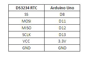
Here is the guide illustrates how to connect an Arduino to the DS3234 Real-Time Clock Module. The following is a table describing which pins on the Arduino should be connected to the pins on the DS3234 module:
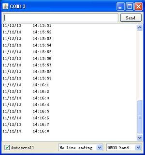
After uploading the sketch, in the serial monitor of the Arduino IDE, we can read the real time.
Example code
[DS3234 Real-Time Clock example]
Document
[DS3234 Real-Time datasheet]
How to buy
Click here to buy [DS3234 Real-Time Clock Module]
